Table of Contents
Advertisement
Quick Links
Advertisement
Table of Contents

Subscribe to Our Youtube Channel
Related Manuals for Servend CT-6


Summary of Contents for Servend CT-6
- Page 1 DI, DIL, & CT SERIES Beverage Dispensers Installation, Use & Care Manual This manual is updated as new information and models are released. Visit our website for the latest manual. www.manitowocfsg.com Leader in Ice & Beverage Dispensers Part Number 020005256 5/15...
- Page 2 Safety Notices Read These Before Proceeding: As you work on Manitowoc equipment, be sure to pay close attention to the safety notices in this manual. ! Caution Disregarding the notices may lead to serious injury and/ Proper installation, care and maintenance are or damage to the equipment.
-
Page 3: Table Of Contents
Table of Contents (continued) Section 1 General Information Read This Manual ..........Unit Inspection . - Page 4 Table of Contents (continued) Pumps ........... . . Auto Bag Selectors .
-
Page 5: Read This Manual
Please read this manual before Beverage Dispensers installation or operation of the machine. A qualified CT-6, CT-8, DI-1522, DI-2323, DIL-2323 service technician must perform installation and start-up of this equipment, consult Section 5 within this manual for service assistance. -
Page 6: Serial Number Location
General Information Section 1 Serial Number Location This number is required when requesting information from your local distributor. The serial number is listed on the SERIAL NUMBER DECAL affixed to the dispenser. Warranty Information Consult your local MBS Distributor for terms and conditions of your warranty. -
Page 7: General System Overview
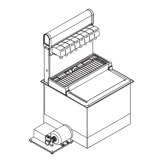
NOTE: Typical Drop-In This is a simplified schematic to show the basic operation of the Internal Carbonation CT-6 beverage system. CT-8 Beverage Dispensing System Carbonate, Non-carbonate Beverage Manifold Carbonator Tank... - Page 8 Installation Instructions Section 2 NOTE: Typical Drop-In Ambient This is a simplified schematic to show the basic operation of the Beverage Dispensing System beverage system. CT-6 CT-8 Carbonate, Non-carbonate Beverage Manifold Carbonate, Non-carbonate Beverage Manifold for DI-1522 2323 1522 SYRUP...
-
Page 9: Unit Dimensions
Section 2 Installation Instructions UNIT DIMENSIONS MODEL 9.50" 14.25" 17.00” 16.38" 22.50” CT-6 (24.2 cm) (36.2 cm) (43.2 cm) (42.8cm) (57.2 cm) 9.50" 15.50" 25.00” 23.75" 22.85” CT-8 (24.2 cm) (39.8 cm) (63.5cm) (60.4cm) (58.1 cm) 44.38” 38.38" 9.50" 15.00"... - Page 10 Installation Instructions Section 2 Grounding Instructions This appliance must be grounded. In the event of Warning malfunction or breakdown, grounding provides a path of When using electric appliances, basic precautions least resistance for electric current to reduce the risk of should always be followed, including the following: electric shock.
-
Page 11: Pre-Installation Checklist
Carbonator Unit Inspection This section covers unpacking, inspecting, selecting location, installing the unit, and preparing for operation. The Servend Stepless (Oetiker) clamps Drop-In is shipped in a heavy duty corrugated carton with a wooden pallet. Inspect the Drop-In for freight... -
Page 12: Step By Step Installation
55 psi or you will 95°F (10°C and 35°C). affect the quality of the carbonation. Step by Step Installation To properly install the Servend Drop-In, Use these guidelines: • Meet all local code requirements. •... -
Page 13: Counter Top Footprints
.313 in (.8 cm) 1.625 in (4.1 cm) 1.625 in (4.1 cm) Cut Out Area 1.188 in (3.0 cm) 1.938 in Perimeter of CT-6 Base (4.9 cm) .250 in (.6 cm) 10.5 in (26.7 cm) 3.625 in (9.2 cm) 6 Holes (See Notes) 1.5 in (3.8 cm) - Page 14 Installation Instructions Section 2 1. The CT-6 tower has (6) .250 inch diameter mounting 3. The correct counter top hole size if screws are used holes in the base. is .125 inches. 2. Diameter of the 6 holes to be drilled in the 4.
-
Page 15: Placing The Unit
Section 2 Installation Instructions PLACING THE UNIT CT-6 & CT-8 CT TOWER COUNTER TOP PRE-CUT OPENING 1. Remove drain pan grid, splash panel and drain pan 8. Connect all necessary plumbing connections and before installation. connect drain to tower. (See Plumbing & Wiring) 2. - Page 16 Installation Instructions Section 2 DI-1522 & DI/DIL-2323 Handles (PN# 4340201) Drain Pan Wood Block Wood Block Counter Top Wood Blocks 1. Set the Drop-In in place resting on the two blocks of pan. Another drain fitting is provided for the ice chest, wood mentioned earlier.
-
Page 17: Carbonator Purge Tube Routing
Section 2 Installation Instructions CARBONATOR PURGE TUBE ROUTING 1. During installation of unit the carbonator tank purge 3. The carbonator tank purge tube (A) will be routed tube (A) must be properly routed to a drain. Once the down through the valve leads conduit and out splash panel has been removed from unit remove twist bottom of unit to a drain. -
Page 18: Plumbing Diagrams
CT-6 WIRING DIAGRAM LIGHTER MERCH. VALVE JUMPER POWER CORD HARNESS POWER CORD COUNTER ELECTRICAL BOX 5029318-0 CT-6 with Variety Valve CAUTION CT-6 RECOMMENDED PLUMBING 2-1-1-2 PLUMBING CONFIGUREATION ELECTRICAL SHOCK HAZARD DISCONNECT POWER BEFORE SERVICING *OPTIONAL* CT-6 WIRING DIAGRAM VARIETY VALVE... - Page 19 Section 2 Installation Instructions CT-8 Post-mix CAUTION CT-8 RECOMMENDED PLUMBING ELECTRICAL SHOCK HAZARD 3-1-1-3 PLUMBING CONFIGUREATION DISCONNECT POWER BEFORE SERVICING CT-8 WIRING DIAGRAM VALVE JUMPER HARNESS LIGHTER MERCH. POWER CORD COUNTER POWER CORD ELECTRICAL BOX 5029282-0 2-13 Part Number 020005256 5/15...
- Page 20 Installation Instructions Section 2 DI-1522 Post-mix DI-1522 Post-Mix with 2 Blocked Valves 2-14 Part Number 020005256 5/15...
- Page 21 Section 2 Installation Instructions DI-1522 Pre-Mix SERVEND RECOMMENDED PLUMBING DI1522 PREMIX VALVE LOCATIONS 3/4” NPT DRAIN PAN DRAIN 3/4” NPT COLD PLATE DRAIN BOTTOM VIEW FOR 5 VALVE UNIT: LINE 6 IS NOT USED FOR 4 VALVE UNIT: LINES 1 & 6 ARE NOT USED...
- Page 22 Installation Instructions Section 2 DI/DIL-2323 6 Valve Post-Mix 020006242-1 DI/DIL-2323 6 Valve Post-Mix with 2 Blocked Valves 2-16 Part Number 020005256 5/15...
- Page 23 Section 2 Installation Instructions DI/DIL-2323 8 Valve Post-Mix 020006242-1 DI/DIL-2323 8 Valve with Variety Valve Information 020001489 2-17 Part Number 020005256 5/15...
- Page 24 Installation Instructions Section 2 DI/DIL-2323 10 Valve Post-Mix 020006242-1 DI/DIL-2323 6 Valve Pre-Mix SERVEND RECOMMENDED PLUMBING DI/DIL-2323 VALVE LOCATIONS 3/4” NPT DRAIN PAN DRAIN 3/4” NPT COLD PLATE DRAIN BOTTOM VIEW FOR 5 VALVE UNIT: INLET 6 IS NOT USED...
- Page 25 Section 2 Installation Instructions Internal Carbonator Connections Purging Air from the Carbonator Tank 1. Unit must be properly plumbed before purging the Water Outlet carbonator tank. (See Plumbing Diagrams Page 2 - 12), without power, and with the CO turned OFF. Water Inlet Important Do not energize the unit or turn on the CO...
- Page 26 Installation Instructions Section 2 Pressure Settings Bag-in-Box (BIB) Start-up 1. Incoming tap water should be at a minimum static All lines should be properly flushed and sanitized before pressure of 40 psi (2.758 bars) and a maximum of starting the unit. See Bag-In-Box System Sanitation Page 4 - 55 psi (3.792 bars) with carbonator pump operating (measured at inlet to pump).
-
Page 27: Starting System & Dispenser
Section 2 Installation Instructions STARTING SYSTEM & DISPENSER Upon completion of the beverage dispenser and / or Adjust Syrup to Water Ratio (Brix) system installation, all tubing, dispenser, and system These are general brix instructions for beverage valves components must be cleaned and sanitized prior to use. using an S-tube syrup separator and high yield brix cup, NOTE: At installation equipment, dispensers, and tubing process may vary depending on valve manufacturer. - Page 28 Installation Instructions Section 2 THIS PAGE INTENTIONALLY LEFT BLANK 2-22 Part Number 020005256 5/15...
-
Page 29: Component Identification
POST-MIX DROP-INS flow of both water and syrup to obtain the proper mixing The design of the Servend Drop-In is such that it ratio. These two components of the beverage are mixed provides high accessibility to the ice stored in the chest, as they leave the valve. -
Page 30: Pre-Mix Drop-Ins
Operation Section 3 PRE-MIX DROP-INS UNIT INSPECTION Pre-mix fountain dispensing consists of a container of This section covers unpacking, inspecting, selecting location, beverage ready for dispensing, beverage delivery installing the unit, and preparing for operation. Thoroughly system, carbon dioxide (CO ) propellant, beverage inspect the unit upon delivery. -
Page 31: Carbonated Water
Section 3 Operation SUPPLY CARBONATED WATER Note: CO inlet for the internal carbonator is located Carbon Dioxide (CO ) leaves the storage tank and with the cold plate inlet lines. arrives at the carbonator tank through the gas inlet. Water supply enters the carbonator pump inlet at regular (See plumbing diagram for exact plumbing location) street water line pressure (minimum 20 PSI, maximum •... -
Page 32: Back Room Package
Operation Section 3 BACK ROOM PACKAGE 7. Primary pressure regulator - Lowers the CO pressure, to 100 psi, so the CO gas will be at the proper pressure to enter the carbonator regulator. Booster System (If Required) 8. Lowered outgoing pressure - Set for 75 psi. Water Regulator From Water Supply Gauge indicates lowered outgoing pressure from the... -
Page 33: Pumps
Section 3 Operation FIGAL TANKS B-I-B The stainless steel Figal beverage tanks are easy to The Bag-In-Box system refers to a plastic disposable store and connect. There are several items to remember bag. The B-I-B normally contains 5 gallons of syrup, when using the Figal tanks: however some locations offer 2-1/2 gallon B-I-B units. - Page 34 Operation Section 3 THIS PAGE INTENTIONALLY LEFT BLANK Part Number 020005256 5/15...
-
Page 35: Maintenance
Section 4 Maintenance Cleaning Warning When using cleaning fluids or chemicals, rubber DISASSEMBLE FOR CLEANING gloves and eye protection should be worn. Clean the exterior and drain pan: 1. Turn off the key switch located on either right or left side of the unit. -
Page 36: Monthly Cleaning
Maintenance Section 4 CLEANING CHECKLIST ! Caution • Check CO supply. If CO supply is low, an arrow on Unplug unit before servicing or cleaning ice bin. the primary regulator gauge will point to a shaded area that reads “Low CO ”... -
Page 37: Sanitizing
Section 4 Maintenance Sanitizing 2. Disconnect the “syrup-line side” of the bag-in-box connector. BEVERAGE SYSTEM CLEANING Warning Flush sanitizing solution from syrup system. Residual sanitizing solution left in system could create a health hazard. Warning When using cleaning fluids or chemicals, rubber gloves and eye protection must be worn. -
Page 38: Figal Beverage System
Maintenance Section 4 9. Allow detergent solution to remain in the system for FIGAL BEVERAGE SYSTEM 5 minutes. 1. Prepare the following in three clean Figal tanks: 10. Connect Bucket 3 to system. • Rinse tank - fill with room temperature tap water. 11. -
Page 39: Figal Beverage System
Section 4 Maintenance FIGAL BEVERAGE SYSTEM 6. Connect rinse tank to the syrup line. Draw clean rinse water through the valve until detergent is 1. Prepare the following in three clean Figal tanks: flushed from the system. • Rinse tank - fill with room temperature tap water. 7. - Page 40 Maintenance Section 4 THIS PAGE INTENTIONALLY LEFT BLANK Part Number 020005256 5/15...
-
Page 41: Before Calling For Service
Section 5 Before Calling for Service Checklist If a problem arises during operation of your dispenser, follow the checklist below before calling service. Routine adjustments and maintenance procedures are not covered by the warranty. DRINK TROUBLESHOOTING Condition Investigation Check Correction Water only dispensing No pressure Regulator(s) out of adjustment... -
Page 42: Pump Troubleshooting
Before Calling for Service Section 5 Pump Troubleshooting Problem Possible Cause Corrective Action Pump motor does not Problem with probe or probe harness. 1. Remove probe electronics. shut off 2. Pass magnetic tip of screwdriver by lower end of tube extending from electronics package. - Page 44 © 2014 Manitowoc Continuing product improvements may necessitate change of specifications without notice. Part Number 020005256 5/15 Manitowoc Beverage Systems 2100 Future Drive Sellersburg, IN 47172, USA Ph: 812-246-7000 Fax: 812-246-7024 Visit us online at: www.manitowocfsg.com...
Need help?
Do you have a question about the CT-6 and is the answer not in the manual?
Questions and answers