
Related Manuals for X-pole A-FRAME


Summary of Contents for X-pole A-FRAME
- Page 1 ® LEADERS IN POLE & AERIAL FITNESS INSTRUCTION MANUAL ® A-FRAME Hoop | Hammock | Silks Aerial Fitness | Yoga | Static Trapeze...
- Page 2 THIS BEFORE OPENING YOUR PACKAGE To get the best from your A-FRAME – with SAFETY being the utmost priority – it is extremely important that you READ & FOLLOW the Instruction Manual from beginning to end and most importantly, understand it! Follow the simple but explicit instructions in this manual to get the best results from your A-FRAME.
- Page 3 BEFORE USING YOUR A-FRAME Mis-using the A-FRAME can be dangerous, not only to the user but also to property and anyone close to the A-FRAME. The use of an A-FRAME is always at the user’s discretion, and it is the user’s responsibility to check the A-FRAME is assembled correctly &...
- Page 4 Aerial Fitness | Yoga | Static Trapeze X-Pole's new Aerial A-Frame is perfect for Aerial Fitness, Yoga, Aerial Hoop/Lycra, Hammock, Silks and static Trapeze. The A-Frame can be used from 2450mm (8ft) up to 3480mm (11.42ft) with multiple heights being selectable in-between.
- Page 5 2450mm (8ft) Fig 1.2 Fig 1.3 When the A-FRAME is at its lowest height, it will require a The A-FRAME could be extended from its lowest height of oor area of 4.4sqm (47 sq-ft) and when fully extended will 2450mm (96.45 Inches) to a height of 3480mm require an area of 8.9sqm (95 sq-ft).
-
Page 6: Checking The Parts
Fig 1.5 CHECKING THE PARTS Please check the contents of your A-FRAME with the contents (Fig 1.5) If anything is missing or damaged, please contact your point of purchase or call your local X-POLE o ce immediately (contact details on the back page). -
Page 7: Removing The Packaging
Contents Diagram. Push the pin in & pull out the Leg connectors at the same time. It is recommended that 2 people unpack the A-Frame and that care is taken to lift correctly. Push pin in & pull out foam Replace the Leg connectors making sure the pin pops out Fig 1.6... - Page 8 Leg Connector Tail of Pin Head of Pin Head of pin outside of A-Frame Fig 1.9 Note: Head of the pin on the outside of the legs and tail being on the inside. 1. Lay the top bar on the ground as illustrated in Fig. 1.8 2.
- Page 9 Head of pin outside of A-Frame As the A-FRAME will be assembled on the oor and then lifted into position, it is important to allow enough space to do so. When lifted into position, make sure the feet are at, by gently shaking the 2 legs each person is holding and slowly pulling outwards.
- Page 10 (optional) *Strop / Sling available from your local xpole dealer or point of purchase Note: Optional longer Top Bar can be purchased to widen your A-Frame. Please contact X-Pole or your local point-of-sale for further details. Copyright © Vertical Leisure Ltd. 2017 | All rights reserved.
- Page 11 Note: We strongly recommend to rig Aerial Hoops using a choked strop method as shown below. Option: 1 Centre Point 700mm Single Point Hoop 1400mm Fig 2.5 *Carabiners & Strops Strop/Sling not supplied. Carabiners Swivel Carabiners Single Point Hoop Option: 2 Dual Point Hoop Fig 2.6 Strop...
- Page 12 Hammock A-FRAME WEIGHT AND LOADINGS CAPACITY The X-POLE A frame is a light weight, portable, frame which has been designed for home and light studio use for Aerial Fitness. The X-POLE A-Frame was not designed for professional performance use or dynamic drops.
- Page 13 Please remember: Top Legs extend rst, then middle, then bottom. Remove both pins at one side of the A-Frame, as illustrated in gure: . With one person lifting – the legs can then be extended and pinned back into position (please ensure that the pins are positioned in the inside of the A-Frame & the legs are pinned back into position using the adjustment line to align).
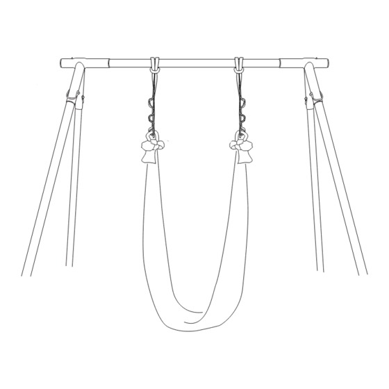
- Page 14 ATTACHMENT OF THE STRAPS Fig 3.0 Insert loops into the strap opening Pull the strap to the centre of the hook. Insert pin through the leg hole at the desired position. Clip the hook onto the pin. Note: The straps can be attached to any pin, even if it is being using to lock the height of the legs.
- Page 15 FILLING & ATTACHING SAND BAG Now that the A-FRAME has been fully assembled and the straps attached, it is now time to secure it in place using the additional sand/weight bags. 1. Firstly the inner Clear Sealable bags must be lled with 3.
- Page 16 DISMANTLING THE A-FRAME 1. Remove the sand bags. Fig 3.2 Press down Feed strap to loosen 2. Remove the straps. 3. Remove both pins at legs numbered 1 whilst another person holds the legs. Slide both legs in. Once the legs have been retracted on one side, lower this down so the feet are touching the oor, now repeat the same process for legs numbered 2, whilst the second person holds the legs.
- Page 17 4. Now that the extended legs have been retracted, and your A-Frame is at the minimum height. Please make sure the pins above the feet are re-inserted to hold the legs in place when they are placed back into the carry cases.
- Page 18 8. Remove connectors. (These are placed back in the square bag.) Push the pin in & pull out the Leg connector at the same time. Push the pin in & pull out the Leg connector at the same time. 9. Remove gure-8 connectors by loosening 5mm hex screws - push pin and slide o . 10.
-
Page 19: Additional Items
ADDITIONAL ITEMS The following items can be purchased to be used in conjunction with your A-FRAME. If you have any questions about sizing or choosing the most appropriate accessory, then please contact your local X-POLE o ces or point of purchase. -
Page 20: Warranty
X-POLE warrants this product against defects in material or workmanship as follows: X-POLE, at its own discretion, will replace at no charge for parts only or, at its option, replace any product or part of the product that proves defective because of improper workmanship and/or material, under normal installation, use, service and maintenance.
Need help?
Do you have a question about the A-FRAME and is the answer not in the manual?
Questions and answers