Table of Contents
Advertisement
Quick Links
Advertisement
Table of Contents

Subscribe to Our Youtube Channel
Related Manuals for Elcon SA5A


Summary of Contents for Elcon SA5A
- Page 1 SWITCH ANALYSER SA5A USER MANUAL 2018-04-20...
-
Page 2: Table Of Contents
3.2.3 Connection of motor ............................... 7 3.3 Connection of transducers ............................. 8 3.4 Connection of a PC ................................. 8 4. OPERATING INSTRUCTION FOR USING SA5A STAND ALONE ....................9 4.1 Before operation ................................9 4.2 Standalone operation of SA5A ............................9 5 Technical Specification. -
Page 3: General Description
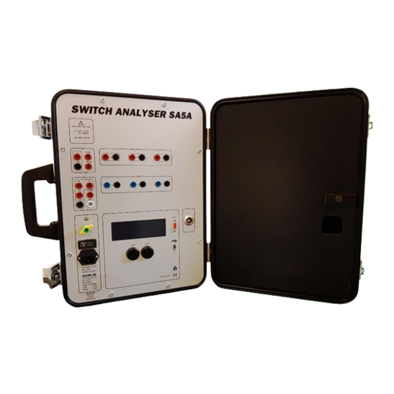
The SA5A must powered with an external AC- or DC- power supply. Environmental SA5A is built in a small metal carry case designed for rough handling in tough outdoor environments. All connections are protected for any possible type of electrical discharges and disturbances. Some of the inputs are even protected against faulty connections up to 300V peak. -
Page 4: Safety Regulations
• Connections. Before connecting the SA5A to a high-voltage circuit breaker, make sure that the breaker poles are in position CLOSE, and disconnected from the power line at both sides. The breaker must also be grounded on at least one side. -
Page 5: Power Supply And Protective Grounding
2.2 POWER SUPPLY AND PROTECTIVE GROUNDIN G The SA5A can be powered from any AC or DC source, 100-250 V. When the SA5A is connected to a wall socket, the socket must be a grounded power outlet. IMPORTANT! The SA5A have a separate grounding terminal (green/yellow) that must be grounded to the nearest protective earth (ground) with a separate wire. -
Page 6: Connections For One Breaking Unit Per Phase
Figure 2.1 Connections for a one breaking unit per phase 3.1.4 CONNECTIONS FOR TWO OR MORE BREAKING UNI TS PER PHASE Note! Only one phase with 2 breaking elements is shown Figure 2.2 Connections for two breaking units per phase www.elcon.se Rev 0 2018-04-20 Go to INDEX. -
Page 7: Connection Of The Breaker Operating Mechanism
Make sure that the powers to these inputs are pre-fused with maximum 32A. • Never do any work on a circuit breaker unless the control circuits of the breaker are disconnected from the SA5A control outputs. (avoiding unintentional breaker operations) Note! The white 4 mm panel socket "ISOL"... -
Page 8: Connection Of Transducers
Use prefabricated cables for connection. 3.4 CONNECTION OF A PC Any standard Windows PC with one free RS232, USB 2.0, USB 3.0 port can be connected. can be connected with 3 different methods. www.elcon.se Rev 0 2018-04-20 Go to INDEX. -
Page 9: Operating Instruction For Using Sa5A Stand Alone
Use a standard straight serial RS232 PC-cable with a 9 pole DSUB Male Female connectors, for connection to 4. OPERATING INSTRUCTION FOR USING SA5A STAND ALONE The instruction below only handles the operating instruction for using the SA5A as a stand-alone instrument. See separate BTS11 User manual for use of the PC-software 4.1 BEFORE OPERATION... -
Page 10: Technical Specification
Inputs: 3 independent Function: Measure contact timing of aux contacts Voltage: 24Vdc Current: Max 11 mA 20s at 50 KHz sampling. Timing resolution: 250VAC / 300VDC Max Voltage between red and black output: www.elcon.se Rev 0 2018-04-20 Go to INDEX. - Page 11 Range 0 - 60A AC. Accuracy < 1% or 0.1 A AC Analog resolution: 14 bits. Resolution ≈ 11.5mA / Bit. COMMUNICATION INTERFACE 1 Marked: RS-232. Protection: Internal isolated Baud rate 115.2 K baud Data size 8-bit www.elcon.se Rev 0 2018-04-20 Go to INDEX.
- Page 12 Transport temperature: -40 - 40 °C Relative humidity 20 - 85% non-condensing Altitude operating 2 000 m Altitude non-operating 12 000 m OVERVOLTAGE CATEGORY: MANUFACTURER: Elcon AB Hyttrisvägen 27 770 14 Nyhammar SWEDEN www.elcon.se Rev 0 2018-04-20 Go to INDEX.
-
Page 13: Maintenance
The Switch Analyzer is a field-test equipment and is constructed to withstand the handling it requires to fulfil its purposes, although the front panel is sensitive for scratches and other marks. The display is the most sensitive point of the SA5A, it will not tolerate harsh management. This should be considered during unpacking and handling of the unit. -
Page 14: Sa5A Program Loader In Display
CPU = 43° PCB = 30° When the display shows • Something happened to the SA5A that made it lose its program. • Connect the unit to computer and start BTS11. • Select what comport unit is connected to. - Page 15 Open the file with the command button “Open” • The new software will now be transferred to the Control unit. This may take a while. When the display shows the following screen the SA5A is ready to use. Ready for Close 31°...
-
Page 16: Adjustments
Refer to BTS11 User manual for operating instructions. All analogue inputs on the SA5A are software calibrated. Calibration can easy be done from a calibration guide. All calibration constants and password for changing constants are saved in the SA5A. NOTE! Password at delivery is “elcon”... -
Page 17: General Calibration Procedure
This is not recommended for tabs “Analog inputs”, “Transducers” and “Resistance”. Use the command button ”Calibration wizard” instead. Command buttons “New Password” Change of current password (The password is saved in SA5A) “Customer settings”: Set a customer instrument No for SA5A “Calibration wizard”... -
Page 18: Calibration Wizard For Voltage Measurement On Analogue Inputs
Page 18 (24) 7.3.1 CALIBRATION WIZARD FOR VOLTAGE MEASUREMENT ON ANALOGUE INPUTS: Select tab “Analog inputs” from the dialogue box “Calibration SA5A”. See paragraph 6.3. Select inputs to be calibrated form the list box. Select command button “Calibration wizard”. The following dialogue box is displayed: Calibration wizard •... - Page 19 Set the voltage source to about -200 V. Enter the value (V) from the reference instrument. Press the command button ”Next” Note: The instrument box shows the voltage value from selected channel measured by the control unit SA5A • Step 4.
-
Page 20: Calibration Wizard For Current Measurement On Analogue Inputs
Page 20 (24) 7.3.2 CALIBRATION WIZARD FOR CURRENT MEASUREMENT ON ANALOGUE INPUTS: Select tab “Analog inputs” from the dialogue box “Calibration SA5A”. See paragraph 6.3. Select inputs to be calibrated from the list box Select command button “Calibration wizard”. The following dialogue box is displayed: Calibration wizard •... - Page 21 Press the command button ”Next”. • Step 5 New calibration constants are now calculated Select button ”Save” to save the new calculated calibration constants. Select button “Cancel” to cancel the guide without updating the calibration constant. www.elcon.se Rev 0 2018-04-20 Go to INDEX.
-
Page 22: Calibration Wizard Of Analogue Transducer Input
Page 22 (24) 7.3.3 CALIBRATION WIZARD OF ANALOGUE TRAN SDUCER INPUT: Select tab “Transducers” from the dialogue box “Calibration SA5A”, see paragraph 6.3. Select command button “Calibration wizard”. The following dialogue box is displayed: Calibration wizard • Step 2 (step 1 not available) Connect a stable DC-voltage source (0-5V) and a voltage instrument to the selected input. - Page 23 Press the command button ”Next”. • Step 5 New calibration constants are now calculated Select button ”Save” to save the new calculated calibration constants. Select button “Cancel” to cancel the guide without updating the calibration constant. www.elcon.se Rev 0 2018-04-20 Go to INDEX.
-
Page 24: Transportation/Scrapping/Recycling
Page 24 (24) 8 TRANSPORTATION/SCRAPPING/RECYCLING. Before transportation remove all cables from the SA5A unit when moving/transportation the equipment. Scrapping/Recycling of replaced components shall be done according to local rules and laws. 9 SA5A ACCESSORIES. All accessories can be ordered directly from Contact us and give us the below information depending on which spare part you are interested in.
Need help?
Do you have a question about the SA5A and is the answer not in the manual?
Questions and answers