Table of Contents
Advertisement
Quick Links
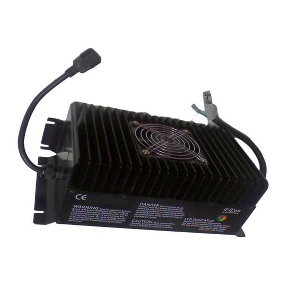
Description
• Advanced high frequency switching design with 92% typical efficiency
• Fully sealed enclosure providing improved reliability in demanding environments
• > 0.98 Power Factor minimizes utility surcharges and maximizes use of AC power
• Approved battery charge algorithms for ideal charging (default I1, I2, U, I3a)
• Memory to store 10 unique algorithms, and tools to load new algorithms in the field
•The internal CPU employs advanced charging management algorithm
Technical Features
DC Output
Model
DC Output Voltage - nominal
DC Output Voltage - maximum 51V
DC Output Current - 230vac
DC Output Current - 115vac
Model
DC Output Voltage - nominal
DC Output Voltage - maximum 170V
DC Output Current - 230vac
DC Output Current - 115vac
Battery Type
Reverse Polarity
Short Circuit
PFC2000+
36XX
48XX
60XX
36V
48V
60V
68V
85V
40A
30A
26A
35A
27A
24A
120XX
144 XX
120V
144V
204V
13A
11A
12A
10A
Specific to selected algorithm
Electronic protection – auto-reset
Output closed automatically
1
72XX
84XX
72V
84V
102V
119V
22A
19A
20A
17A
156XX
168XX
156V
168V
221V
238V
10A
9A
9A
8A
96XX
96V
136V
15A
13A
288XX
288V
408V
5.5A
5A
Advertisement
Table of Contents

Subscribe to Our Youtube Channel
Related Manuals for Elcon PFC2000+


Summary of Contents for Elcon PFC2000+
- Page 1 PFC2000+ Description • Advanced high frequency switching design with 92% typical efficiency • Fully sealed enclosure providing improved reliability in demanding environments • > 0.98 Power Factor minimizes utility surcharges and maximizes use of AC power • Approved battery charge algorithms for ideal charging (default I1, I2, U, I3a) •...
- Page 2 AC Input AC Input Voltage - range 90 - 260VAC AC Input Voltage - nominal 120 VAC / 230 VAC AC Input Frequency 45 - 65 Hz AC Input Current - maximum Current – nominal 14 A rms @ 120 VAC / 9.5 A rms @ 230 VAC AC Power Factor - nominal >...
- Page 3 Connect to coil of main contactor, DC/DC converter or controller enable wires. Normally battery voltage +, but OV while charging. Note: The current through green Interlock wire must not exceed 2A. Choice of Charging Curve (curve 1~10) 1.The LED will flash red several times when AC is first connected, then the LED will flash green once.
- Page 4 3. Ensure all heat-dissipating parts are not obstructed to avoid overheating. Do not put the battery charger near any heat sources. Make sure that free space around the charger is enough to provide adequate ventilation & easy cable socket access. 4.
Need help?
Do you have a question about the PFC2000+ and is the answer not in the manual?
Questions and answers