Table of Contents
Advertisement
Advertisement
Table of Contents

Subscribe to Our Youtube Channel
Related Manuals for Elcon SA10A


Summary of Contents for Elcon SA10A
-
Page 1: Rev 1
SWITCH ANALYZER SA10A USER MANUAL 2018-03-21 www.elcon.se Rev 1... -
Page 2: Table Of Contents
1 General description........................4 2 Safety regulations Important! ....................5 2.1 General safety regulations............................5 2.2 Connection of SA10A to mains power........................7 3.0 Connections ..........................7 3.1 Connections for time measurement........................7 3.1.1 Safety regulations..............................7 3.1.2 Principals for connections to SA10A. - Page 3 6.4 Every year or when necessary..........................18 6.5 Battery Fuse ................................. 19 6.7 Upgrading SA10A internal software........................20 6.8 SA10A PROGRAM LOADER in display........................21 7 Adjustments..........................22 7.1 General................................. 22 7.1.1 Instrument needed............................... 22 7.2 Calibration and functional test.
-
Page 4: General Description
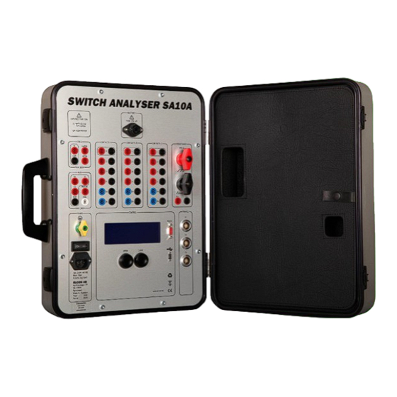
The SA10A must powered with an external AC- or DC- power supply. Environmental SA10A is built in a small metal carry case designed for rough handling in tough outdoor environments. All connections are protected for any possible type of electrical discharges and disturbances. Some of the inputs are even protected against faulty connections up to 300V peak. -
Page 5: Safety Regulations Important
Follow local safety regulations for work on high-voltage circuit breakers. To avoid unintentional breaker operation! Never do any work on a circuit breaker unless the control circuits of the breaker are disconnected from the SA10A control outputs or from any other remote control device. -
Page 6: Ground
The power supplies for coils and motor must be interlocked to a security circuit that cut the power if the security circuit is open. Read also additional safety regulations presented in sections below. 3.1.1 Safety regulations. 3.2.1 Safety regulations. 3.3.1 Safety regulations. 3.4.1 Safety regulations. www.elcon.se Rev 1 2018-03-21 Go to INDEX. -
Page 7: Connection Of Sa10A To Mains Power
2.2 CONNECTION OF SA10A TO MAINS POWE R. The SA10A can be powered from any AC source 100-240V or DC source 100-240 VDC (with a ground connection). When the SA10A is connected to a wall socket, the socket must be a grounded power outlet. -
Page 8: Connections For Two Or More Breaking Units Per Phase
There is no difference between connecting a breaker unit with a pre-insertion resistor and connecting a breaker unit without a pre-insertion resistor. Note! The value of the pre-insertion resistor must be in the range 50 - 5000 ohm Figure. 2.3 Connections for a breaking unit with a pre-insertion resistor www.elcon.se Rev 1 2018-03-21 Go to INDEX. -
Page 9: Connections For A Resistance Measurement Of A Breaking Unit
Note! If there is a current transformer (CT) in the circuit, the 200A current from SA10A shall if possible be connected so that the 200A measuring current not go through the CT. If that not possible, the secondary windings of the CT must be short circuit and the CT must be demagnetized after done test. -
Page 10: Connections For Resistance Measurement Of A Pre-Insertion Resistor
Connect a reference resistor between output COILS:CLOSE and measuring input AUX:Ul. Connect the pre-insertion resistor between AUX:Ul” and AUX:COM. Connect the breaker coils to the SA10A for a normal CO-operation (not shown in figure 2.5). Note! Do not connect the motor to SA10A. See 3.4.2 Connection of operating coils. -
Page 11: Connection Of The Breaker Operating Mechanism
Make sure that the powers to these inputs are pre-fused with maximum 32A. • Never do any work on a circuit breaker unless the control circuits of the breaker are disconnected from the SA10A control outputs. (avoiding unintentional breaker operations) Note! The white 4 mm panel socket "ISOL"... -
Page 12: Connection Of Transducers
If computer is not equipped with RS232 port an USB to RS232 adapter can be used. • Bluetooth communication kit Use a standard straight serial RS232 PC-cable with a 9 pole DSUB Male Female connectors, for connection to www.elcon.se Rev 1 2018-03-21 Go to INDEX. -
Page 13: Using Sa10A Stand Alone
Read chapter 2 Safety regulations before any connections. 4.2 STANDALONE OPERATION OF SA10A The SA10A LCD-display and two operation buttons "OPEN" and "CLOSE" for simpler operations and measurements. Starting up the display will present the version of the internal software. - Page 14 Voltage measured in millivolt. 205.5 A 20.55 mV Note! To prevent overheating of the unit and depletion of the batteries. A timer in the top right corner counts down until next resistance measuring can be performed. www.elcon.se Rev 1 2018-03-21 Go to INDEX.
-
Page 15: Technical Specification
2 RS422 quadrature inputs Analog min resistance: 100 ohm. 5 V DC, accuracy 0,005V DC Voltage measure: Analog resolution: 14 bits. Resolution ≈ 0.6mV / Bit Power output: +5 VDC 100 mA. www.elcon.se Rev 1 2018-03-21 Go to INDEX. - Page 16 Range 0-90A DC. Accuracy < 1% or 0.1 A DC Current measure: Range 0 - 60A AC. Accuracy < 1% or 0.1 A AC Analog resolution: 14 bits. Resolution ≈ 11.5mA / Bit. www.elcon.se Rev 1 2018-03-21 Go to INDEX.
- Page 17 Transport temperature: -40 - 40 °C Relative humidity 20 - 85% non-condensing Altitude operating 2 000 m Altitude non-operating 12 000 m OVERVOLTAGE CATEGORY: MANUFACTURER: Elcon AB Hyttrisvägen 27 770 14 Nyhammar SWEDEN www.elcon.se Rev 1 2018-03-21 Go to INDEX.
-
Page 18: Maintenance
The Switch Analyzer is a field-test equipment and is constructed to withstand the handling it requires to fulfil its purposes, although the front panel is sensitive for scratches and other marks. The display is the most sensitive point of the SA10A, it will not tolerate harsh management. This should be considered during unpacking and handling of the unit. -
Page 19: Battery Fuse
(one is spare fuse) counterclockwise) 8. Insert the fuse into the fuse holder 9. Insert the fuse with the cap into 10. Screw and tighten the fuse cap. the fuse holder. holder. (Turn clockwise) www.elcon.se Rev 1 2018-03-21 Go to INDEX. -
Page 20: Upgrading Sa10A Internal Software
Page 20 (40) 6.7 UPGRADING SA10A INTERNAL SOFTWARE. • Run BTS11 setup and install BTS11 software. • Start BTS11 • Select what comport unit is connected to. • In menu Service click Control Unit… • Select tab About and click button Update…... -
Page 21: Sa10A Program Loader In Display
Open the file with the command button “Open” • The new software will now be transferred to the Control unit. This may take a while. When the display shows the following screen the SA10A is ready to use. Ready for Close 31°... -
Page 22: Adjustments
Calibration can easy be done from a calibration guide. All calibration constants and password for changing constants are saved in the Note! Password at delivery is “elcon” Principle of calibration. Two points are measured at abt.10 respective about 90% of full scale for selected input. The values are measured with both the and a connected reference instrument. -
Page 23: Calibration And Functional Test
Analog resolution: 12 bits. Resolution about 0.225V DC / Bit. If the values are near the limit of accuracy, calibration is necessary. See. 7.3.1 Calibration wizard for voltage measurement inputs Uc, Uk, Ul, Um. www.elcon.se Rev 1 2018-03-21 Go to INDEX. -
Page 24: Check Current Measurement Inputs Ic, Im
Range 0 - 32 A AC. Accuracy < 2% or 0.2 A AC Analog resolution: 12 bits. Resolution about 0.048A DC / Bit. If the values are near the limit of accuracy, calibration is necessary. See. 7.3.2 Calibration wizard for current measurement inputs Ic, Im. www.elcon.se Rev 1 2018-03-21 Go to INDEX. -
Page 25: Check Transducer Inputs T1, T2, T3
Analog measurement: Analog resolution: 12 bits. Resolution about 0.0014V DC / Bit If not values are in range, recalibration is required. See section. 7.3.3 Calibration wizard for analogue transducer inputs T1, T2, T3. www.elcon.se Rev 1 2018-03-21 Go to INDEX. -
Page 26: Check Resistance Measuring Inputs Ur, Ir
Ir 0 - 240 A DC. Accuracy < 2A DC Current measure Analog resolution: 12 bits. Resolution about 0.07A DC / Bit. Res 0 - 1000 ohm. Accuracy < 2ohm. Resistance measure: www.elcon.se Rev 1 2018-03-21 Go to INDEX. -
Page 27: Grounding
Test current for all auxiliary contacts should be 8 - 12mA. Indication in service menu for each contact should be seen. To open this window in Click function Control unit from the menu Service. Select tab Contacts. www.elcon.se Rev 1 2018-03-21 Go to INDEX. -
Page 28: Recalibration Procedure
For tab Analogue Inputs the inputs is selected from a dropdown list box. Command buttons New Password. Change of current password (The password is saved in SA10A). Customer settings. With this button you can change the instrument number assigned to the unit. - Page 29 7.3.1 Calibration wizard for voltage measurement inputs Uc, Uk, Ul, Um. To open window Calibration SA10A see 7.3 Recalibration procedure. Select tab Analog inputs in the window Calibration SA10A. Click on button Calibration wizard. The following window is displayed. •...
- Page 30 Calibration wizard. Step 7. Check that the measured value compared to the reference instrument is within the accuracy for the input. If not Click Re-calibrate button. If correct click Cancel button to exit Calibration Wizard. www.elcon.se Rev 1 2018-03-21 Go to INDEX.
-
Page 31: Calibration Wizard For Current Measurement Inputs Ic, Im
Page 31 (40) 7.3.2 CALIBRATION WIZARD FOR CURRENT MEASUREMENT INPUTS IC, IM. To open window Calibration SA10A see 7.3 Recalibration procedure. Click tab Analogue Inputs in window Calibration SA10A. Click on button Calibration wizard. The following window is displayed. •... - Page 32 Calibration wizard. Step 7. Check that the measured value compared to the reference instrument is within the accuracy for the input. If not Click Re-calibrate button. If correct click Cancel button to exit Calibration Wizard. www.elcon.se Rev 1 2018-03-21 Go to INDEX.
-
Page 33: Calibration Wizard For Analogue Transducer Inputs T1, T2, T3
Page 33 (40) 7.3.3 CALIBRATION WIZARD FOR ANALOGUE TRANSDUCER INPUTS T1, T2, T3. To open window Calibration SA10A see 7.3 Recalibration procedure. Click tab Transducers in window Calibration SA10A. Click on button Calibration wizard. The following window is displayed. •... - Page 34 • Calibration wizard. Step 7. Check that the measured value compared to the reference instrument is within the accuracy for the input. If not Click Re-calibrate button. If correct click Cancel button to exit Calibration Wizard. www.elcon.se Rev 1 2018-03-21 Go to INDEX.
-
Page 35: Calibration Of Resistance Measurement Input Ur
Page 35 (40) 7.3.4 CALIBRATION OF RESISTANCE MEASUREMENT INPUT UR. To open window Calibration SA10A see 7.3 Recalibration procedure. Click tab Resistance in window Calibration SA10A. Click on button Calibration wizard. The following window is displayed. • Calibration wizard. Step 1. - Page 36 • Calibration wizard. Step 7. Check that the measured value compared to the reference instrument is within the accuracy for the input. If not Click Re-calibrate button. If correct click Cancel button to exit Calibration Wizard. www.elcon.se Rev 1 2018-03-21 Go to INDEX.
-
Page 37: Calibration Of Resistance Measurement Input Ir
Calibration of the current for resistance measurement is done by using the input Ur as a voltage reference instrument and a current shunt as a reference resistor. To open window Calibration SA10A see 7.3 Recalibration procedure. Click tab Resistance in window Calibration SA10A. Click command button Calibration wizard. The following dialogue box is displayed. -
Page 38: Enter Password
If correct click Cancel button to exit Calibration Wizard. 7.3.6 ENTER PASSWORD. When saving for the first time a dialog will appear to enter password. Default password from factory is elcon Note! This dialog will only appear once. BTS11 will keep the password in memory. -
Page 39: Transportation/Scrapping/Recycling
Before transportation remove all cables from the SA10A unit when moving/transportation the equipment. Put the SA10A and the cables in intended locations in a transporting case (can be ordered from ELCON AB) Scrapping/Recycling of replaced components shall be done according to local rules and laws. -
Page 40: Ce-Declaration
EMC Directive 2004/108/EC Low Voltage Directive 2006/95/EC Type of equipment Test equipment for test of HV-circuit breakers in field Brand name or trade mark Switch Analyzer SA10A Type designation(s)/Model no(s) SA10A Manufacturer’s name, address, telephone & fax no Elcon AB Hyttrisvägen 27...
Need help?
Do you have a question about the SA10A and is the answer not in the manual?
Questions and answers