
Related Manuals for Wacker Neuson CT 36


Summary of Contents for Wacker Neuson CT 36
- Page 1 0163091en 1007 Walk-Behind Trowels CT 36 CT 48 REPAIR MANUAL...
- Page 3 CT Repair Foreword This manual covers machines with Item Number: 0009438, 0009439, 0009442, 0009443, 0009444, 0009447, 0009449, 0009450, 0009452, 0009453, 0620106 Operating / Parts Information You must be familiar with the operation of this machine before you attempt to troubleshoot or make any repairs to it. Basic operating and maintenance procedures are described in the operator’s / parts manual supplied with the machine.
- Page 4 CT Repair Foreword This manual provides information and procedures to safely operate and maintain this Wacker model. For your own safety and protection from injury, carefully read, understand and observe the safety instructions described in this manual. Keep this manual or a copy of it with the machine. If you lose this manual or need an additional copy, please contact Wacker Corporation.
-
Page 5: Table Of Contents
CT Repair Table of Contents Safety Information Laws Pertaining to Spark Arrestors ............8 Operating Safety .................. 9 Operator Safety while using Internal Combustion Engines ....10 Service Safety ..................11 Label Locations .................. 12 Safety and Information Labels ............13 Technical Data Dimensions and Weight .............. - Page 6 Table of Contents CT Repair Maintenance Periodic Maintenance Schedule - Honda ..........40 Periodic Maintenance Schedule - Wacker ..........41 Engine Oil - Honda ................42 Engine Oil - Wacker ................43 Air Cleaner - Honda ................44 Air Cleaner - Wacker ................45 Spark Plug ...................46 Cleaning Sediment Cup - Honda ............47 Cleaning Fuel Strainer - Wacker ............47 4.10...
- Page 7 CT Repair Table of Contents Spider Spider Assembly—Exploded View ............. 78 Spider Assembly—Components ............79 Replacing the Blades ................. 80 Replacing the Arms ................82 Balancing the Blade Pitch ..............84 Removing the Spider ................86 Installing the Spider ................88 Rebuilding the Lift Ring Assembly ............
-
Page 8: Safety Information
Safety Information CT 36 / CT 48 Safety Information This manual contains DANGER, WARNING, CAUTION, NOTICE and NOTE callouts which must be followed to reduce the possibility of personal injury, damage to the equipment, or improper service. This is the safety alert symbol. It is used to alert you to potential personal injury hazards. -
Page 9: Operating Safety
CT 36 / CT 48 Safety Information Operating Safety Familiarity and proper training are required for the safe operation of machine. Machines operated improperly or by untrained personnel can be dangerous. Read the operating instructions contained in both WARNING this manual and the engine manual and familiarize yourself with the location and proper use of all controls. -
Page 10: Operator Safety While Using Internal Combustion Engines
Safety Information CT 36 / CT 48 1.2.15 ALWAYS operate machine with all safety devices and guards in place and in working order. DO NOT modify or defeat safety devices. DO NOT operate machine if any safety devices or guards are missing or inoperative. -
Page 11: Service Safety
CT 36 / CT 48 Safety Information Service Safety Poorly maintained machines can become a safety hazard! In order for the machine to operate safely and properly over a long period of time, periodic maintenance and occasional repairs are necessary. -
Page 12: Label Locations
Safety Information CT 36 / CT 48 Label Locations wc_si000139gb.fm... -
Page 13: Safety And Information Labels
CT 36 / CT 48 Safety Information Safety and Information Labels Wacker machines use international pictorial labels where needed. These labels are described below: Label Meaning DANGER! Engines emit carbon monoxide; operate only in well-ventilated area. Read the Operator’s Manual. - Page 14 Safety Information CT 36 / CT 48 Label Meaning WARNING! Remove pan from trowel before lifting machine R e m o v e p a n f r o m t r o w e l b e f o r e...
- Page 15 CT 36 / CT 48 Safety Information Label Meaning A nameplate listing the model number, item number, revision number, and serial number is attached to each unit. Please record the infor- mation found on this plate so it will be available should the nameplate become lost or dam- aged.
- Page 16 Safety Information CT 36 / CT 48 Label Meaning Open the fuel flow valve. Close the choke. Turn engine key switch to “ON” position. Place throttle in the IDLE position. Pull the rewind starter. Open the choke. wc_si000139gb.fm...
- Page 17 CT 36 / CT 48 Safety Information Label Meaning Press the stop button. Turn engine key switch to “OFF” position. Close the fuel flow valve. wc_si000139gb.fm...
-
Page 18: Technical Data
Technical Data CT 36 / CT 48 Technical Data Dimensions and Weight Guide Description Ref. Description Ref. Honda engine* Variable Speed Engine Horse Power 4, 5, 6, 8, 9, 11, 13 *Standard models feature Wacker engine. Pitch Weight Handle Type Item No. - Page 19 CT 36 / CT 48 Technical Data without handle with handle LxWxH LxWxH without with Model Item No. weight kit weight kit (in.) (in.) kg (lbs.) kg (lbs.) 0009438 915x915x607 2005x915x1040 CT 36-5A 85 (183) 91 (201) 0620106 (36x36x24) (79x36x41)
-
Page 20: Engine
Technical Data CT 36 / CT 48 Engine Item No. CT 36-5A CT 36-6 0009438, 0620106 0009443 Engine Engine Make Honda Wacker Engine Model GX 160 K1 QX2 WM170 Rated Power 4.3 (5.7) @ 3800rpm kW (Hp) 4.2 (5.6) @ 3800 rpm... - Page 21 CT 36 / CT 48 Technical Data Item No. CT 36-8A CT 36-8A-V CT36-9 CT 36-9-V 0009439 0009442 0009444 0009447 Engine Engine Make Honda Wacker Engine Model GX 240 K1 QA WM270 Rated Power kW (Hp) 6.2 (8.3) @ 3800 rpm 6.5 (8.7) @ 3800 rpm...
- Page 22 Technical Data CT 36 / CT 48 Item No. CT 48A-8A CT 48-9 0009449 0009453 Engine Engine Make Honda Wacker Engine Model GX 240 K1 QA WM270 Rated Power kW (Hp) 6.2 (8.3) @ 3800 rpm 6.5 (8.7) @ 3800 rpm...
- Page 23 CT 36 / CT 48 Technical Data Item No. CT 48-11A CT 48-13A-V 0009450 0009452 Engine Engine Make Honda Engine Model GX 340 K1 QA GX 390 U1 QA Rated Power kW (Hp) 8.7 (11.6) @ 3800 rpm 10 (13.4) @ 3800 rpm...
-
Page 24: Trowel
Technical Data CT 36 / CT 48 Trowel Model Item No. Trowel Number Gear Box Speed Pitch Diameter* Lubrication Range Range Blades mm (in.) type/ml (oz.) degrees Trowel 0009438 CT 36-5A 0620106 60–125 CT 36-6 0009443 CT 36-8A 0009439 60–125... -
Page 25: Sound And Vibration Data
CT 36 / CT 48 Technical Data Sound and Vibration Data The required sound specification, Paragraph 1.7.4.f of 89/392/EEC Machinery Directive, is: • the sound pressure level at operator’s location (L ) : “A” dB(A) • the guaranteed sound power level (L ) = “B”... -
Page 26: Operation
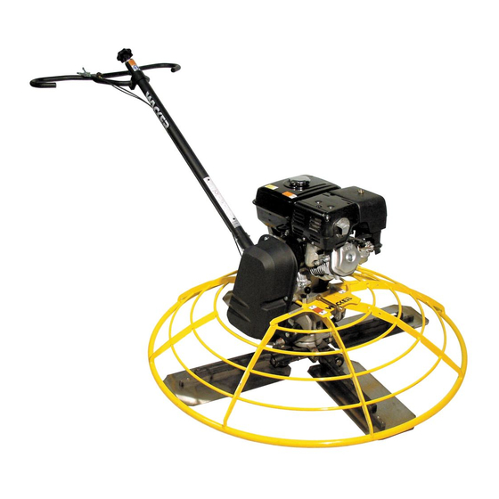
Operation CT 36 / CT 48 Operation Application This trowel is a modern, high production machine intended for floating and finishing freshly poured concrete slabs. The machine's good balance, adjustable handle, and easily reached controls add to operator comfort and productivity. An automatic stop sensor provides added operator safety. -
Page 27: Installing Blades
CT 36 / CT 48 Operation Installing Blades See Graphic: wc_gr003238 There are four types of blades available for the trowels. Float pans are large "pizza pan" style blades, which hook on over finish or combination blades and are available for the 36" machines only. Float blades are available for all machines and clip on over finish or combination blades. -
Page 28: Installing And Adjusting Handles
Operation CT 36 / CT 48 Installing and Adjusting Handles See Graphic: wc_gr001758, wc_gr003219 On new machines the pipe handle comes assembled with the pitch control (Twist or Pro-Shift®) (c), stop button (b), throttle (a), screws (g), and nut (m). - Page 29 CT 36 / CT 48 Operation wc_gr001758 wc_tx000373gb.fm...
-
Page 30: Controls
Operation CT 36 / CT 48 Controls See Graphic: wc_gr003219 Ref. Description Ref. Description Throttle lever Handle height adjustment (if equipped) Stop button Foldable handle adjustment (if equipped) Twist pitch control or Pro-Shift® pitch control wc_tx000373gb.fm... -
Page 31: Stop Button
CT 36 / CT 48 Operation Stop Button See Graphic: wc_gr003219 When the stop button (b) is pressed, the engine will shut off. To prevent uncontrolled spinning of the trowel, the engine control module is designed to shutoff the engine under certain conditions. For... -
Page 32: To Start - Honda
Operation CT 36 / CT 48 To Start - Honda See Graphic: wc_gr003219, wc_gr001098 3.9.1 Open fuel valve by moving lever to the right (g1). Note: If engine is cold, move choke lever to closed position (i1). If engine is hot, set choke to open position (i2). -
Page 33: To Stop - Honda
CT 36 / CT 48 Operation wc_gr001098 3.10 To Stop - Honda See Graphic: wc_gr003219, wc_gr001098 3.10.1 Reduce engine RPM to idle by moving the throttle lever to idle position (a1). 3.10.2 Push the stop button (b). 3.10.3 Turn engine switch to “OFF” (h2). -
Page 34: To Start - Wacker
Operation CT 36 / CT 48 3.11 To Start - Wacker See Graphic: wc_gr003219, wc_gr002747 3.11.1 Open fuel valve by moving lever down (g1). Note: If engine is cold, move choke lever to close position (i2). If engine is hot, set choke to open position (i1). -
Page 35: To Stop - Wacker
CT 36 / CT 48 Operation wc_gr002747 3.12 To Stop - Wacker See Graphic:wc_gr003219, wc_gr002747 3.12.1 Reduce engine RPM to idle by moving the throttle lever to idle position (a1). 3.12.2 Push the stop button (b). 3.12.3 Turn engine switch to “OFF” (h1). -
Page 36: Engine Control Module
Operation CT 36 / CT 48 3.13 Engine Control Module To prevent uncontrolled spinning of the trowel, the engine control module is designed to shutoff the engine under certain conditions. For example, if the operator loses his/her grip on the trowel, the engine control module will sense that the machine is spinning and shut off the engine. - Page 37 CT 36 / CT 48 Operation 3.14.6 To move to the right press down slightly on the handle (d). 3.14.7 Clean trowel after each use to remove concrete splatter. Allow the muffler to cool before cleaning or servicing the machine. A hot muffler could ignite the fuel and start a fire.
-
Page 38: Braking System
Operation CT 36 / CT 48 3.15 Braking System The braking system of the trowel is spring loaded. The brake is engaged anytime the input shaft of the gearbox is not rotating and/or there is no resistance placed against the blades of the trowel. The brake is released when the input shaft is rotated and is shifted out from its seated position. -
Page 39: Pitch Adjustment
CT 36 / CT 48 Operation 3.16 Pitch Adjustment See Graphic: wc_gr003220 To adjust blade pitch (angle): A = Twist pitch: turn the pitch adjusting knob (a) clockwise to increase pitch and counterclockwise to decrease pitch. B = Pro-Shift®: pull the handle (b) towards the operator to increase pitch and away from the operator to decrease pitch. -
Page 40: Maintenance
Maintenance CT 36 / CT 48 Maintenance Periodic Maintenance Schedule - Honda The chart below lists basic machine and engine maintenance. Refer to engine manufacturer’s Operator’s Manual additional information on engine maintenance. After Every Every Every Daily first 20 hrs. -
Page 41: Periodic Maintenance Schedule - Wacker
CT 36 / CT 48 Maintenance Periodic Maintenance Schedule - Wacker The chart below lists basic machine and engine maintenance. Refer to engine manufacturer’s Operator’s Manual additional information on engine maintenance. Daily After Every Every Every Every first 20 2 weeks... -
Page 42: Engine Oil - Honda
Maintenance CT 36 / CT 48 Engine Oil - Honda See Graphic: wc_gr002381 4.3.1 Drain oil while the engine is still warm. 4.3.2 Remove the oil fill plug (a) and drain cap (b) to drain oil. Note: In the interests of environmental protection, place a plastic sheet and a container under the machine to collect any liquid which drains off. -
Page 43: Engine Oil - Wacker
CT 36 / CT 48 Maintenance Engine Oil - Wacker See Graphic: wc_gr003201 4.4.1 Drain oil while engine is still warm. Note: In the interests of environmental protection, place a plastic sheet and a container under the machine to collect any liquid which drains off. -
Page 44: Air Cleaner - Honda
Maintenance CT 36 / CT 48 Air Cleaner - Honda See Graphic: wc_gr000025 The engine is equipped with a dual element air cleaner. Service air cleaner frequently to prevent carburetor malfunction. NOTICE: NEVER run engine without air cleaner. Severe engine damage will occur. -
Page 45: Air Cleaner - Wacker
CT 36 / CT 48 Maintenance Air Cleaner - Wacker See Graphic: wc_gr000656 NEVER use gasoline or other types of low flash point solvents for cleaning the air cleaner. A fire or explosion could result. WARNING NOTICE: NEVER run engine without air cleaner. Severe engine damage will occur. -
Page 46: Spark Plug
Maintenance CT 36 / CT 48 Spark Plug See Graphic: wc_gr000028 Clean or replace the spark plug as needed to ensure proper operation. Refer to the engine owner’s manual. The muffler becomes very hot during operation and remains hot for a while after stopping the engine. -
Page 47: Cleaning Sediment Cup - Honda
CT 36 / CT 48 Maintenance Cleaning Sediment Cup - Honda See Graphic: wc_gr000029 4.8.1 Turn the fuel valve off. 4.8.2 Remove the sediment cup (a) and the O-ring (b). 4.8.3 Wash both thoroughly in a nonflammable solvent. Dry and reinstall them. -
Page 48: Adjusting Idle Speed - Honda
Maintenance CT 36 / CT 48 4.10 Adjusting Idle Speed - Honda See Graphic: wc_gr001122 Remove the drive belt before making any adjustment to the carburetor. See Belt Replacement. The blades will engage unless the belt is removed from the machine. -
Page 49: Carburetor Adjustment - Honda
CT 36 / CT 48 Maintenance 4.11 Carburetor Adjustment - Honda See Graphic: wc_gr0001061 Remove the drive belt before making any adjustment to the carburetor. See Belt Replacement. The blades will engage unless the belt is removed from the machine. -
Page 50: Belt Replacement
Maintenance CT 36 / CT 48 4.12 Belt Replacement See Graphic: wc_gr002380, wc_gr003221 The trowel is equipped with a self-adjusting clutch. This clutch automatically tightens the belt and compensates for belt wear. Replace the belt if the clutch can no longer tighten belt enough to engage gearbox without slipping. -
Page 51: Trowel Lubrication
CT 36 / CT 48 Maintenance 4.13 Trowel Lubrication See Graphic: wc_gr001755 Grease trowel arms (b) with Shell Alvania RL2 grease or equivalent. Oil the pitch control cable and other parts of trowel on an as needed basis. Oil in the gearbox should not require replacement unless it was drained to service gearbox. -
Page 52: Lifting
Maintenance CT 36 / CT 48 4.15 Lifting See Graphic: wc_gr001762 NEVER lift the machine solely by the handle. The component may fail, causing the machine to fall, possibly injuring bystanders. WARNING See Technical Data for the weight of the machine. - Page 53 CT 36 / CT 48 Maintenance wc_tx000374gb.fm...
-
Page 54: Storage
Maintenance CT 36 / CT 48 4.16 Storage If trowel is being stored for more than 30 days: • Change engine oil. • Drain fuel from engine. • Remove spark plug and pour 15 ml (½ ounce) of SAE 30 engine oil into the cylinder. -
Page 55: Troubleshooting
CT 36 / CT 48 Maintenance 4.17 Troubleshooting Problem / Symptom Reason / Remedy Trowel does not develop full • Remove deposits built up in engine cylinder and speed. engine head. • Engine speed too low. Adjust speed. • Clean or replace air filter. -
Page 56: Guide Handle
Guide Handle CT Repair Guide Handle Replacing the Throttle Cable See Graphic: wc_gr003362 Disassembly: 5.1.1 Remove the engine air cleaner (d) if necessary to gain access to the throttle cable at the engine. Unclamp the throttle cable from the throttle casing clamp (g). - Page 57 CT Repair Guide Handle Honda Honda Wacker wc_gr003362 wc_tx000551gb.fm...
-
Page 58: Adjusting The Throttle Lever
Guide Handle CT Repair Adjusting the Throttle Lever See Graphic: wc_gr003361 The throttle lever is used to vary the speed of the engine and to control the rpm of the trowel blades to meet specific applications and job conditions. 5.2.1 Be sure the engine’s throttle control can obtain the idle (slow) position. - Page 59 CT Repair Guide Handle wc_gr003361 wc_tx000551gb.fm...
-
Page 60: Upper Handle/Twist Pitch Control-Exploded View
Guide Handle CT Repair Upper Handle/Twist Pitch Control—Exploded View " " & & wc_tx000551gb.fm... -
Page 61: Upper Handle/Twist Pitch Control-Components
CT Repair Guide Handle Upper Handle/Twist Pitch Control—Components Ref. Description Ref. Description Handle Push button switch Retaining ring Spring Bearing holder Ball Wiring harness Tie cable Cable Hex head screw Throttle cable Hex head screw Kit-CT throttle Flat head screw Pitch control knob Socket head screw Plate... -
Page 62: Replacing The Upper Handle
Guide Handle CT Repair Replacing the Upper Handle See Graphic: wc_gr003360 Disassembly: 5.5.1 Remove the throttle lever (a) and the throttle cable from the upper handle. See section Replacing the Throttle Cable. 5.5.2 Disconnect and remove the stop switch (b). See section Replacing the Stop Switch. - Page 63 CT Repair Guide Handle wc_gr003360 wc_tx000551gb.fm...
-
Page 64: Replacing The Twist Pitch Control Cable
Guide Handle CT Repair Replacing the Twist Pitch Control Cable See Graphic: wc_gr003363 Disassembly: 5.6.1 Remove the upper handle. See section Replacing the Upper Handle. 5.6.2 Remove the hex head screw (a) from the handle and the socket head screw (b) from the underside of the twist control assembly (c). 5.6.3 Pull the twist control assembly and the pitch control cable (d) from handle. - Page 65 CT Repair Guide Handle wc_gr003363 wc_tx000551gb.fm...
-
Page 66: Replacing The Lower Handle
Guide Handle CT Repair Replacing the Lower Handle See Graphic: wc_gr003156 Disassembly: 5.7.1 Remove the upper handle. See section Replacing the Upper Handle. 5.7.2 Remove the two locknuts (80) and washers (73) from the screws (60). 5.7.3 Pull the lower handle (17) from the gearbox. 5.7.4 If replacing the pulley (25), pull the cotter pin (46) from the clevis pin (42) and remove the pulley. -
Page 67: Replacing The Stop Switch
CT Repair Guide Handle Replacing the Stop Switch See Graphic: wc_gr003371 To replace the stop screw (a), carry out the following procedures: Removal: 5.8.1 Remove the protective boot (b). 5.8.2 Disconnect the wire (c). 5.8.3 Unthread the stop switch from the handle. Installation: 5.8.4 Thread the stop switch (a) into the handle. - Page 68 Guide Handle CT Repair Notes wc_tx000551gb.fm...
-
Page 69: Clutch
CT Repair Clutch Clutch Replacing the Drive Belt See Graphic: wc_gr003153 and wc_gr003382 The trowel is equipped with the standard self-adjusting clutch or a variable speed clutch. Replace the belt if the clutch can no longer tighten the belt enough to engage the gearbox without slipping. The procedure to change the belt is the same for both clutches. -
Page 70: Drive Belt-Standard Clutch
Clutch CT Repair Drive Belt—Standard Clutch wc_gr003153 Ref. Description Ref. Description Beltguard Hex head screw Beltguard plate Hex head screw Clutch assembly Fender washer Pulley Flat steel washer V-belt Washer Spacer Screw Key (square) Hex head screw wc_tx000552gb.fm... -
Page 71: Drive Belt-Variable Speed Clutch
CT Repair Clutch Drive Belt—Variable Speed Clutch 69 53 wc_gr003382 Ref. Description Ref. Description Upper belt guard Hex head screw Beltguard plate Fender washer Clutch Washer Clutch pulley Washer Belt Spacer Lower beltguard Screw Hex head Screw wc_tx000552gb.fm... -
Page 72: Replacing The Standard Clutch
Clutch CT Repair Replacing the Standard Clutch See Graphic: wc_gr003153, wc_gr002068 Removal: 6.4.1 Remove the drive belt as described in section Replacing the Drive Belt. 6.4.2 Remove the screw (51) and the washer (72) that secure the clutch assembly (23) to the crankshaft. 6.4.3 Loosen the setscrew(s) (2) on the clutch assembly. -
Page 73: Standard Clutch-Exploded View
CT Repair Clutch Standard Clutch—Exploded View wc_gr002068 Ref. Description Ref. Description Clutch assembly (incl. 2–8) Clutch shoe Setscrew Ball bearing Clutch plate Clutch drum Spring Clutch pulley wc_tx000552gb.fm... -
Page 74: Standard Clutch Overhaul
Clutch CT Repair Standard Clutch Overhaul See Graphic: wc_gr002068 and wc_gr003364 This procedure requires a propane torch or similar heating device. Disassembly: 6.6.1 Remove the setscrew (2). Slide the clutch plate (3) off of the clutch pulley shaft (8). 6.6.2 Remove and inspect the clutch shoes (5), the clutch spring (4) and the clutch drum (7). - Page 75 CT Repair Clutch wc_gr002068 wc_gr003364 wc_tx000552gb.fm...
-
Page 76: Replacing The Variable Speed Clutch
Clutch CT Repair Replacing the Variable Speed Clutch See Graphic: wc_gr003383, wc_gr002068 Removal: 6.7.1 Remove the drive belt. See section Replacing the Drive Belt. 6.7.2 Remove the bolt (51) that secures the clutch (23) to the engine drive shaft and slide the clutch from the engine drive shaft. Note: Use a gear puller if necessary. - Page 77 CT Repair Clutch 69 53 wc_gr003383 wc_tx000552gb.fm...
-
Page 78: Spider
Spider CT Repair Spider Spider Assembly—Exploded View wc_tx000553gb.fm... -
Page 79: Spider Assembly-Components
CT Repair Spider Spider Assembly—Components Ref. Description Ref. Description Spider Cotter pin Blade lift ring Hex head screw Bearing holder Hex head screw Tube Lifting bolt Yoke Setscrew Link Screw Eccentric adjuster Screw Bearing sleeve Plug (threaded) Ball bearing Fender washer Cap plug Washer Grease fitting... -
Page 80: Replacing The Blades
Spider CT Repair Replacing the Blades See Graphic: wc_gr003365 If any blade requires replacement, replace all the blades. The blades can become extremely sharp. Use great care when replacing the blades. WARNING Disconnect or remove the spark plug to avoid accidentally starting the engine when turning the trowel blades. - Page 81 CT Repair Spider wc_gr003365 wc_tx000553gb.fm...
-
Page 82: Replacing The Arms
Spider CT Repair Replacing the Arms See Graphic: wc_gr003356 The blades can become extremely sharp. Use great care when replacing the blades. WARNING Disconnect or remove the spark plug to avoid accidentally starting the engine when turning the trowel blades. WARNING Removal: 7.4.1... - Page 83 CT Repair Spider 180˚ wc_gr003356 wc_tx000553gb.fm...
-
Page 84: Balancing The Blade Pitch
Spider CT Repair Balancing the Blade Pitch See Graphic: wc_gr003357 To prevent wobble and for optimum performance balance the blade pitch. Carry out the following procedures whenever the blades or any of the arms have been replaced, or if the trowel is not performing as it should. - Page 85 CT Repair Spider wc_gr003357 wc_tx000553gb.fm...
-
Page 86: Removing The Spider
Spider CT Repair Removing the Spider See Graphic: wc_gr003154 Disconnect or remove the spark plug to avoid accidentally starting the engine when turning the trowel blades. See section Engine Wiring. WARNING This procedure requires an appropriate hoist or crane to lift the trowel. 7.6.1 Pitch the blades so they lie flat (0°... - Page 87 CT Repair Spider wc_tx000553gb.fm...
-
Page 88: Installing The Spider
Spider CT Repair Installing the Spider See Graphic: wc_gr003154 7.7.1 Install the setscrews (61) into the spider so that all but one thread is threaded into the spider. 7.7.2 Apply Alvania #2 or equivalent to the grease fittings (41) and install them into the spider. - Page 89 CT Repair Spider wc_tx000553gb.fm...
-
Page 90: Rebuilding The Lift Ring Assembly
Spider CT Repair Rebuilding the Lift Ring Assembly See Graphic: wc_gr003358 Inspect the lift ring assembly for wear or damage. Replace any damaged or worm component. This procedure requires an Arbor or similar press. Disassembly: 7.8.1 Remove the retaining ring (88). 7.8.2 Press the bearing holder (10) from the blade lift ring (9). - Page 91 CT Repair Spider wc_gr003358 wc_tx000553gb.fm...
-
Page 92: Drivetrain
Drivetrain CT Repair Drivetrain Drivetrain—Exploded View wc_tx000554gb.fm... -
Page 93: Drivetrain-Components
CT Repair Drivetrain Drivetrain—Components Ref. Description Ref. Description Guard ring Lockwasher Beltguard plate Flat washer Spacer Flat washer Engine control module (gyro Locknut switch) Stud Locknut Screw Oil drain fitting Pan head screw Pipe cap Flat head screw wc_tx000554gb.fm... -
Page 94: Engine Removal
Drivetrain CT Repair Engine Removal See Graphic: wc_gr003155 8.3.1 To gain access to the throttle cable at the engine, remove the air cleaner. Then, disconnect the throttle cable from the engine throttle bracket. See section Replacing the Throttle Cable. 8.3.2 Cut the tie-wraps holding the harness to the engine and remove the harness. - Page 95 CT Repair Drivetrain wc_tx000554gb.fm...
-
Page 96: Engine Installation
Drivetrain CT Repair Engine Installation See Graphic: wc_gr003155 8.4.1 Align the engine with the engine studs on the guard ring. Place the washer (73) and the ring terminal of the engine control module (gyro switch) (37) over the engine stud. Place the washers (68) over all the studs and secure the engine with the locknuts (79). - Page 97 CT Repair Drivetrain wc_tx000554gb.fm...
-
Page 98: Engine Wiring
Drivetrain CT Repair Engine Wiring wc_gr003370 wc_tx000554gb.fm... -
Page 99: Engine Wiring Components
CT Repair Drivetrain Engine Wiring Components See Graphic: wc_gr003369 and wc_gr003370 Ref. Description Ref. Description Spark plug Handle Ignition module Handle ground wire* Engine ON/OFF switch Engine ground wire* Engine control module Harness (loom) Oil alert unit Cable tie To stop switch Engine mount plate Low oil switch Stop switch... -
Page 100: Wiring Diagrams
Drivetrain CT Repair Wiring Diagrams Wacker Honda wc_gr003369 wc_tx000554gb.fm... -
Page 101: Engine Wiring Components
CT Repair Drivetrain Engine Wiring Components See Graphic: wc_gr003369 and wc_gr003370 Ref. Description Ref. Description Spark plug Handle Ignition module Handle ground wire* Engine ON/OFF switch Engine ground wire* Engine control module Harness (loom) Oil alert unit Cable tie To stop switch Engine mount plate Low oil switch Stop switch... -
Page 102: Replacing The Gearbox
Drivetrain CT Repair Replacing the Gearbox See Graphic: wc_gr003359 Removal: 8.9.1 Remove the handle. See section Replacing the Lower Handle. 8.9.2 Remove the spider. See section Removing the Spider. 8.9.3 Remove the clutch as described in section Replacing the Standard Clutch. - Page 103 CT Repair Drivetrain wc_gr003359 wc_tx000554gb.fm...
-
Page 104: Gearbox-Exploded View
Drivetrain CT Repair 8.10 Gearbox—Exploded View wc_gr003367 wc_tx000554gb.fm... -
Page 105: Gearbox-Components
CT Repair Drivetrain 8.11 Gearbox—Components Ref. Description Ref. Description Gearbox complete Spacer Gearbox Relief valve Gearbox cover Plug (threaded) Gearbox cover Hex head screw Worm gear Input shaft Output shaft Key (square) Brake cone Retaining ring Brake cup O-Ring Roller bearing O-Ring Needle bearing Shim... -
Page 106: Gearbox Disassembly
Drivetrain CT Repair 8.12 Gearbox Disassembly See Graphic: wc_gr003157 and wc_gr003366 There are two very similar gearboxes used on CT trowels. Early versions used a cup-and-cone–style brake (a), later versions a disc- type brake (b). Any differences in the procedures to rebuild the gearboxes are called out. - Page 107 CT Repair Drivetrain wc_gr003157 wc_tx000554gb.fm...
- Page 108 Drivetrain CT Repair 8.12.10 Remove the screws (54) from the side cover (7) and remove the side cover. Inspect the O-ring (90) and replace it if it is worn. 8.12.11 For gearboxes with cup-and-cone–style brakes (a), press the brake cup (22) from the side cover using a hydraulic press. For gearboxes with disc-type brakes (b), press the brake disc (94).
- Page 109 CT Repair Drivetrain wc_gr003366 wc_tx000554gb.fm...
-
Page 110: Gearbox Assembly
Drivetrain CT Repair 8.13 Gearbox Assembly See Graphic: wc_gr003367 and wc_gr003368 8.13.1 Install a new needle bearing (30) into the gearbox. 8.13.2 Press the roller bearing (29) onto the input shaft (19). 8.13.3 Press the roller bearing race into the gear box. 8.13.4 Install a new seal (32) and O-ring (90) into the side cover (7). - Page 111 CT Repair Drivetrain wc_gr003368 wc_gr003367 wc_tx000554gb.fm...
- Page 112 Drivetrain CT Repair Notes wc_tx000554gb.fm...
- Page 113 Threadlockers and Sealants Threadlockers and Sealants Threadlocking adhesives and sealants are specified throughout this manual by a notation of “S” plus a number (S#) and should be used where indicated. Threadlocking compounds normally break down at temperatures above 175°C (350°F). If a screw or bolt is hard to remove, heat it using a small propane torch to break down the sealant.
- Page 114 Threadlockers and Sealants Threadlockers and Sealants (continued) Threadlocking adhesives and sealants are specified throughout this manual by a notation of “S” plus a number (S#) and should be used where indicated. Threadlocking compounds normally break down at temperatures above 175°C (350°F). If a screw or bolt is hard to remove, heat it using a small propane torch to break down the sealant.
- Page 115 Torque Values Torque Values Metric Fasteners (DIN) TORQUE VALUES (Based on Bolt Size and Hardness) WRENCH SIZE 10.9 12.9 Size ft.lb. ft.lb. ft.lb. Metric Inch Metric Inch 7/32 – 9/32 – 5/16 – – – – 11/16 – – – 15/16 –...
- Page 116 Torque Values Torque Values (continued) Inch Fasteners (SAE) Size ft.lb. ft.lb. ft.lb. Metric Inch Metric Inch No.4 – 3/32 No.6 5/16 – 7/64 No.8 11/32 – 9/64 No.10 – – 5/32 – 7/16 – 3/32 5/16 – – 9/16 – 5/16 7/16 –...
- Page 118 Wacker Construction Equipment AG · Preußenstraße 41 · D-80809 München · Tel.: +49-(0)89-3 54 02 - 0 · Fax: +49 - (0)89-3 54 02-3 90 Wacker Corporation · P.O. Box 9007 · Menomonee Falls, WI 53052-9007 · Tel. : (262) 255-0500 · Fax: (262) 255-0550 · Tel. : (800) 770-0957 Wacker Asia Pacific Operations ·...
Need help?
Do you have a question about the CT 36 and is the answer not in the manual?
Questions and answers