Advertisement
Table of Contents
- 1 Table of Contents
- 2 Explanation of Symbols
- 3 General Health and Safety Guidance
- 4 Additional Health and Safety Guidance for Bandsaws
- 5 Features of the 403, 503 and 603 Bandsaws
- 6 Specifications
- 7 Dust Extraction
- 8 Installation and Operation
- 9 Operation and Bandsawing Practice
- 10 Maintenance
- 11 Troubleshooting
- 12 Parts Lists and Diagrams - 403/UK1 and 403/UK3
- 13 Parts Lists and Diagrams - 503/UK3
- 14 Parts Lists and Diagrams - 603/UK3
- 15 Electrical Connection and Wiring Diagrams
- 16 EU Declaration of Conformity
- Download this manual
Original Instruction Manual
403 16" Trade Bandsaw
503 20" Trade Bandsaw
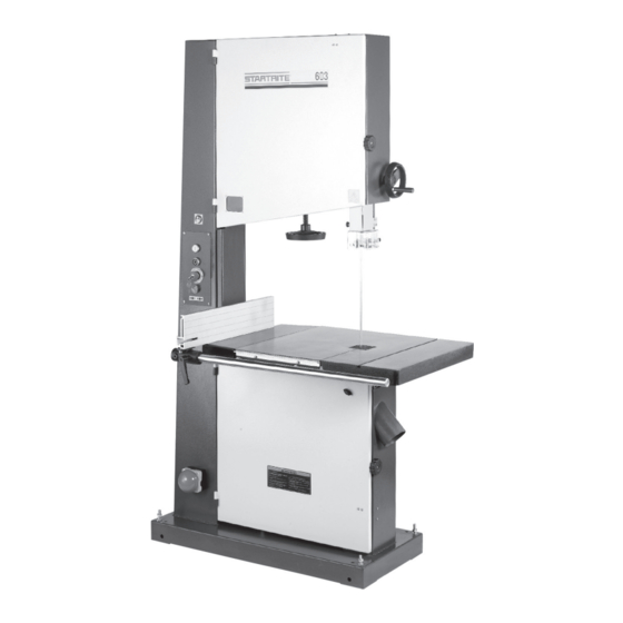
603 24" Trade Bandsaw
Version 3.4
December 2017
Kg
Always wear safety glasses when
using woodworking equipment.
Important
i
For your safety read instructions carefully before
assembling or using this product.
Always read the instructions
provided before using
Save this manual for future reference.
woodworking equipment.
Advertisement
Table of Contents


Need help?
Do you have a question about the 403 and is the answer not in the manual?
Questions and answers
How does the brake work
The brake on the STARTRITE 403 works by using a brake switch that must be in the ON position. When the brake switch is ON, pressing the ON button starts the bandsaw. To stop the bandsaw, you can press either the OFF button or the emergency stop button.
This answer is automatically generated