Advertisement
Quick Links
Overview
The EXB family of ICSLan Device Control Boxes provides Ethernet-based remote port
expansion for NetLinx Central Controllers which can provide remote ports for a master
(eliminating the need to implement another Central Controller), or to provide large numbers of
ports in a rack-mount environment.
EXB ETHERNET MODULES - PRODUCT FAMILY
Name
FG#
Description
EXB-COM2
FG2100-22
ICSLan Serial Interface, 2 Ports
EXB-I/O8
FG2100-21
ICSLan Input/Output Interface, 8 Channels
EXB-IRS4
FG2100-23
ICSLan IR/S Interface, 4 IR/S and 4 Inputs
EXB-MP1
FG2100-26
ICSLan Multi-Port, 1 COM, 1 IR/S, 2 I/O, 1 IR RX
EXB-REL8
FG2100-20
ICSLan Relay Interface, 8 Channels
Common Features
Many features are common to all products in the EXB family, as described in the following
table. Module-specific connector descriptions are in the following section. For additional
details on the individual modules, refer to the EXB Ethernet Modules Operation/Reference Guide
(available online at www.amx.com).
EXB MODULES - COMMON FEATURES
Dimensions (HWD):
• EXB-COM2, -I/O8, -IRS4 and -REL8:
1.00" x 4.35" x 5.15" (25.48 x 110.36 x 130.81)
• EXB-MP1:
1.00" x 3.04" x 4.82" (25.48cm x 77.14cm x 122.43cm)
Weight:
• EXB-COM2: 1 lb (454 g)
• EXB-I/O8: 1 lb (454 g)
• EXB-IRS4: 1 lb (454 g)
• EXB-MP1: 0.75 lb (280 g)
• EXB-REL8: 1 lb (454 g)
Power Requirements:
PoE (Power-over-Ethernet).
Idle (minimum) Power Draw:
EXB-COM2:
40mA 1.92 watts
EXB-IO8:
30mA 1.44 watts
EXB-IRS4:
40mA 1.92 watts
EXB-MP1
40mA 1.92 watts
EXB-REL8:
40mA 1.92 watts
Enclosure:
Metal with black matte finish
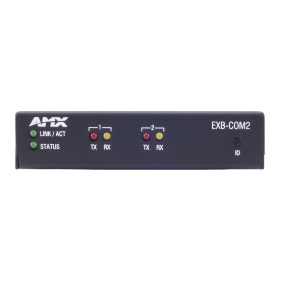
Front Panel Components
ID Pushbutton:
The ID Pushbutton serves four functions:
• ID Mode: Used in conjunction with the ID Mode feature in NetLinx Studio,
a momentary push assigns a device address to the Module. See the
Using ID Mode to Set the Device Address on the EXB Modules section in
the Instruction Manual for details.
• Static/DHCP: If the button is pressed and held for 10 seconds or longer
and then released, the unit toggles between static and dynamic IP
addressing. See the Toggling Between Static and DHCP IP Addressing
section in the Instruction Manual for details.
• Factory Reset: If the ID button is held for 10 seconds or longer during
the boot process, the unit will reset to factory defaults. See the
Performing a Factory Reset section in the Instruction Manual for details.
• Factory Image: If the ID pushbutton is held for 20 seconds and released
while the Module is booting up, the Module will restore itself to a factory
firmware image. See the Resetting the Unit to the Factory Default
Firmware Image section in the Instruction Manual for details.
Status LED:
The green Status LED indicates unit status.
See the Detailed LED Behavior section in the Instruction Manual for details.
L/A LED:
The green L/A (Link / Active) LED indicates communication status.
See the Detailed LED Behavior section in the Instruction Manual for details.
Rear Panel Components
Ethernet / PoE
RJ-45 connector provides IP communication and PoE.
Connector
This is an Auto MDI/MDI-X enabled port, therefore either straight-through
or crossover Ethernet cables can be used.
Note: The Ethernet connector is located on the front panel of the
EXB-MP1.
Storage/Operating
• Operating Temperature: 0° C (32° F) to 40° C (104° F)
Environment:
• Storage Temperature: -10° C (14° F) to 60° C (140° F)
• Operating Humidity: 5% to 85% RH (non-condensing)
• Heat Dissipation (Typical): 36.9 BTU/hr
• Designed for indoor use only.
Certifications:
FCC Part 15 Class B, CE, and IEC 60950
Included Accessories:
Phoenix (captive-wire) connectors - varies as required by model. See the
Operation/Reference Guide for details.
Other AMX Equipment
• NXA-ENET8POE Gigabit Ethernet Switch (FG2178-62)
• PS-POE-AF PoE Injector (FG423-80)
• AVB-VSTYLE-SURFACE-MNT V-Style Module Surface Mount
(FG1010-722)
• AVB-VSTYLE-RMK-1U V-Style Module Tray (FG1010-720)
• AVB-VSTYLE-RMK-FILL-1U V-Style Module Tray w/ fill plates
(FG1010-721)
• AVB-VSTYLE-POLE-MNT V Style Module Pole Mount (FG1010-723)
Busy (maximum) Power Draw
40mA 1.92 watts
40mA 1.92 watts
50mA 2.4 watts
40mA 1.92 watts
70mA 3.36 watts
ICSLan Device Control Boxes
SAFETY INSTRUCTIONS
•
For UL compliance, the EXB family of ICSLan Device Control Boxes should be powered
directly via any listed external IEC/UL 60950-1 2nd edition certified LPS PoE switch or
injector, such as the AMX NXA-ENET8POE or PS-POE-AF.
•
The EXB family of ICSLan Device Control Boxes are intended for Network Environment 0
per IEC TR62101, and are to be connected only to PoE networks without routing to the
outside plant.
Connections and Wiring
LAN/PoE Port
The LAN/PoE (RJ45) port on all EXB Modules provides 10/100 BaseT network connectivity.
Use standard Cat5/6/6E ethernet cable to connect the EXB Module to the LAN. The following
table lists the pinouts, signals, and pairing for the Network port.
LAN/POE PORT PINOUTS AND SIGNALS
Pin
Signals
Connections
1
TX +
1 --------- 1
2
TX -
2 --------- 2
3
RX +
3 --------- 3
4
DC +
4 --------- 4
5
DC +
5 --------- 5
6
RX -
6 --------- 6
7
DC -
7 --------- 7
8
DC -
8 --------- 8
The Ethernet Port LEDs show communication activity, connection status, speeds, and mode
information:
•
SPD (speed) - Yellow LED lights On when the connection speed is 100 Mbps and turns
Off when the speed is 10 Mbps.
•
L/A (link/activity) - Green LED lights On when the Ethernet cables are connected and
terminated correctly, and blinks when receiving Ethernet data packets.
Module-Specif ic Connectors
EXB-COM2
Port 1(Multi-Protocol COM Port)
Port 1 (multi-protocol port) is a 10-pin 3.5mm captive-wire connector that supports RS-232/
422/485 serial communication. The following table provides the pinout configuration:
EXB-COM2 COM 1 PORT PINOUTS
Wiring Conf iguration
Signal
Function
RS-232
GND
Signal ground
X
RXD
Receive data
X
TXD
Transmit data
X
CTS
Clear to send
X
RTS
Request to send
X
TX+
Transmit data
TX-
Transmit data
RX+
Receive data
RX-
Receive data
+12 VDC
Power
optional
Port 2 (RS-232 only)
Port 2 is a 5-pin 3.5mm captive-wire connector that supports RS-232 (only) serial
communication. Pins 1-5 on COM2 provide the same RS-232 functions as pins 1-5 on the
COM1 connector:
EXB-COM2 PORT 2 PIN ASSIGNMENTS
Signal
Function
GND
Signal ground
RXD
Receive data
TXD
Transmit data
EXB-I/O8
Port 1 (I/O 1-8)
Port 1 is a 10-pin 3.5mm captive-wire connector that provides eight I/O contacts (1-8) as well
as PWR and GND.
EXB-I/O8 I/O8 CONNECTOR PIN ASSIGNMENTS
Signal
Function
+12V
+12VDC (max current 200 mA)
8 -1
Channels 8 - 1
GND
Ground
•
When used for voltage inputs, the I/O port detects a low signal (0 - 1.5 VDC) as a Push,
and a high signal (3.3 - 5 VDC) as a Release.
•
Although a high signal is defined as 3.3 - 5 VDC, this port can handle up to 12V without
harm.
•
When used for outputs, the I/O port acts as a switch to GND and is rated for 200mA @
12 VDC.
Note: The I/Os on this Module are not dry closure; they are electronic switches that float at 3V
when Off. Therefore, they should not be expected to work in situations that require true dry
contact (or dry closure). The I/Os do work with AMX PC1, PC2, UPC20 and UPC20+.
QUICK START GUIDE
Pairing
1 --------- 2
White-Orange
3 --------- 6
White-Green
White-Blue
White-Brown
RS-422
RS-485
X
X
X
(strap to pin 8)
X
X
(strap to pin 9)
X
X
(strap to pin 6)
X
X
(strap to pin 7)
optional
Signal
Function
CTS
Clear to send
RTS
Request to send
Color
Orange
Blue
Green
Brown
Advertisement

Related Manuals for AMX EXB-COM2


Summary of Contents for AMX EXB-COM2
-
Page 1: Quick Start Guide
Note: The I/Os on this Module are not dry closure; they are electronic switches that float at 3V when Off. Therefore, they should not be expected to work in situations that require true dry contact (or dry closure). The I/Os do work with AMX PC1, PC2, UPC20 and UPC20+. - Page 2 HARMAN. Oracle, Java and any other company or brand name referenced may be trademarks/registered trademarks of their respective companies. AMX does not assume responsibility for errors or omissions. AMX also reserves the right to alter specifications without prior notice at any time.