
Related Manuals for Riverstone Networks Monticello 8x20


Summary of Contents for Riverstone Networks Monticello 8x20
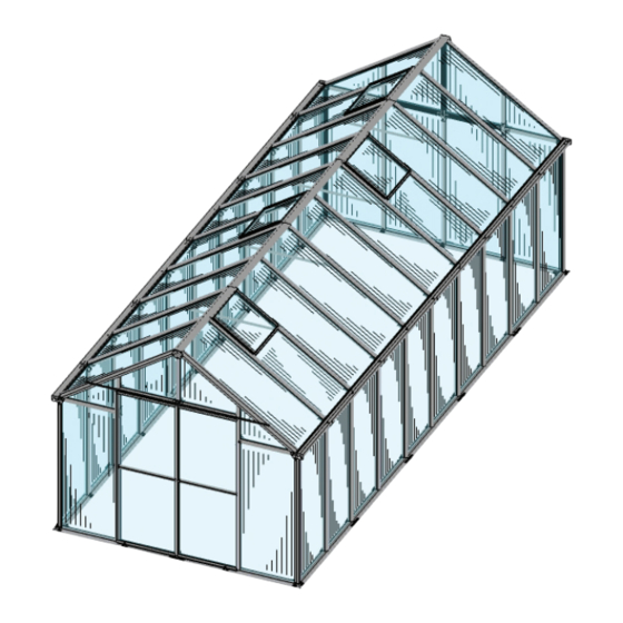
- Page 1 Monticello Made in the USA 8’ x 20’ Greenhouse Assembly Instructions 071812 YE A R WARR ANT Y Customer Service: (877) 373-3078 Email: customerservice@risww.com 65 Fleetwood Drive, Rockaway, NJ 07866...
-
Page 2: Introduction
Introduction Thank you for purchasing your Monticello 8x20 Greenhouse. The Monticello line is proudly made in the USA by a leading commercial greenhouse maker using the same professional grade materials and design. The frame is constructed with the highest quality extruded aluminum with lead free powder-coated paint. The panels are professional grade 8mm twin wall polycarbonate selected for their insulation and durability. -
Page 3: Table Of Contents
Safety Advice Table of Contents Introduction .......... The greenhouse must be positioned and xed on a at Safety Advice ........level surface. General Order of Assembly ..... Dispose of all plastic bags safely. Keep them out of the Construct Wood Platform ....reach of small children. -
Page 4: Construct Wood Platform
Constructing a Wood Platform IMPORTANT: It is very important to begin with a level surface. Check your foundation to ensure it is level at every point. If you are not building on a wood deck, we recommend constructing a wood platform so you can properly secure the greenhouse. -
Page 5: List Of Parts
List of Parts WARNING: Pro les with cut edges and/or drilled holes are sharp. Use extreme caution when handling. The greenhouse is shipped in seven cartons. These cartons are heavy. Use care when lifting them. Some parts have sharp edges. Use extreme caution when handling. Wear proper safety gear including work shoes, gloves and safety goggles. - Page 6 List of Parts (continued) WARNING: Use extreme caution when handling panels with cut edges. The corners are sharp. Panels Connectors Steps Steps 2,3,4,8 24” x 57” Step 5 Step 8 24” x 32 ¼” Steps 2,3,4,5,10 Steps 24” x 15 ½” Step 8 Step 5 24”...
- Page 7 List of Parts (continued) Connectors Hardware Step 9 Steps S-2A Steps S-2B 1,2,3,4,5, 6,7,810,11 S-2C Step 7 Step 10 Steps Trim Plates 1,11 S-5A Step 7 Step 5 S-5B Step 8 S-2C Step 8 49 ⅜” Step 9 Step 8 48 ½”...
-
Page 8: Prepare Set Screws
Assemble Base Make certain the pieces are in the correct positions before assembling. Carefully follow the order of assembly to ensure an easy installation. Wear proper safety gear including work shoes, gloves and goggles. 1.1A We use a set screw and nut assembly S-2B system for ease of installation. - Page 9 Separate pro les to install set screws into inside and outside bolt tracks. BACK Some of the set screws will be secured in this step. Most are used in later steps. They are di cult to install after IMPORTANT: Position P-2A and P-2B pro les at back of greenhouse.
- Page 10 1.4A Make certain side pro les are straight and ush. Adjust position of set screws in inner bolt track at front of pro le to t holes in B-5 connector. Center connector over seam for maximum hold. Secure using ve bolts. Repeat on outer bolt track to install nine remaining B-5 connectors at back and sides.
-
Page 11: Assemble Right Wall
Assemble Right Wall NOTE: Have the hex shaped indent facing up. Screw in until it is ush with bottom of nut so it slides easily into bolt tracks. After inserting into bolt track, screw in until it holds in place. Make certain the pieces are in the correct positions before assembling. - Page 12 2.2A Begin at front right corner. Remove plastic lm from both sides of one W-1 panel. Fit panel into channel in base, placing side marked “ UV Resistant” facing outside. The panels will help hold the pro les up during assembly. Place F-7 corner pro le on base, ing panel into channel.
- Page 13 2.5A Prepare two G-1 gu er pro les by sliding four set screws into bo om bolt track. Hand tighten each end set screw to hold in place. 2.5B Prepare three G-2 gu er pro le with six set screws and one G-2 gu er pro le with ve set screws.
- Page 14 2.7A The gu ers are secured together using B-5 connectors and a ached to side pro les using B-3 connectors on the outside of the greenhouse. The B-3 connector uses the set screw in the center hole of B-5 connectors at seams. Loosen and slide set screws to line up with connectors making sure the seams line up and the gu ers remain straight.
-
Page 15: Assemble Back Wall
Assemble Back Wall NOTE: Have the hex shaped indent facing up. Screw in until it is ush with bottom of nut so it slides easily into bolt tracks. After inserting into bolt track, screw in until it holds in place. Make certain the pieces are in the correct positions before assembling. - Page 16 3.2A Working from inside, remove plastic lm from both sides of one W-1 panel. Fit panel into channel in base and corner pro le, placing side marked “ UV Resitant” facing outside. IMPORTANT: The panels expand and contract depending on the temperature. To ensure proper placement, use the 23 inch spacer included with the tools.
- Page 17 The two sets of F-6 and F-10 pro les t on top of W-1 panels. Line up bo om bolt channels with top edge of F-1 and F-7 vertical pro les. Pro les will t snugly. 3.4A Working from inside right corner, place F-6 pro le with mitered end next to corner and angled edge facing up onto corner W-1...
-
Page 18: Assemble Left Wall
Assemble Left Wall NOTE: Have the hex shaped indent facing up. Screw in until it is ush with bottom of nut so it slides easily into bolt tracks. After inserting into bolt track, screw in until it holds in place. Make certain the pieces are in the correct positions before assembling. - Page 19 4.2A Continue working from inside back left corner. Remove plastic lm from both sides of one W-1 panel. Fit panel into channel in base and corner pro le, placing side marked “ UV Resistant” facing outside. IMPORTANT: The panels expand and contract depending on the temperature. To ensure proper placement, use the 23 inch spacer included with the tools.
-
Page 20: Pro Le At Each End And The Four Longer
4.4A Prepare two G-1 gu er pro les by sliding four set screws into bo om bolt track. Hand tighten each end set screw to hold in place. Prepare three G-2 gu er pro le with six set screws 4.4B and one G-2 gu er pro le with ve set screws. - Page 21 4.6A The gu ers are secured together using B-5 connectors and a ached to side pro les using B-3 connectors on the outside of the greenhouse. The B-3 connector uses the set screw in the center hole of B-5 connectors at seams. Loosen and slide set screws to line up with connectors making sure the seams line up and the gu ers remain straight.
-
Page 22: Assemble Front Wall And Gable
Assemble Front Wall and Gable NOTE: Have the hex shaped indent facing up. Screw in until it is ush with bottom of nut so it slides easily into bolt tracks. After inserting into bolt track, screw in until it holds in place. Make certain the pieces are in the correct positions before assembling. - Page 23 Working from inside front left corner, remove plastic lm from both sides 5.3A of one W-1 panel. Fit panel into channel in base and corner pro le, placing side marked “ UV Resistant” facing outside. IMPORTANT: The panels expand and contract depending on the temperature. To ensure proper placement, use the 23 inch spacer included with the tools.
- Page 24 Working from inside front right corner, install F-1 pro le next to W-1 panel. 5.4A Place 23 inch spacer on base next to F-7 corner pro le and slide F-1 pro le against spacer to ensure proper placement. IMPORTANT: The panels expand and contract depending on the temperature. To ensure proper placement, use the 23 inch spacer included with the tools.
- Page 25 The door frame is 65¼” high from the base. To avoid adjusting the placement after assembly, prepare door frame using the exact measurements listed in these steps. 5.5A Prepare one F-4 pro le. Slide two set screws into bolt track and position as shown.
- Page 26 5.6A Working from inside, remove plastic lm from both sides of two W-3 panels. Fit each panel into channels in pro les, placing side marked “ UV Resistant” facing outside. WARNING: The corners of W-3 panels are 5.6C Secure with two bolts. sharp.
- Page 27 5.9A Prepare two F-7 corner pro les. Slide three set screws into the same bolt track, two on one end and one on other end of pro le. Position one set screw in center of pro le. It will be used in a later step. Tighten each set screw to hold in place.
-
Page 28: Assemble Back Gable
Assemble Back Wall NOTE: Have the hex shaped indent facing up. Screw in until it is ush with bottom of nut so it slides easily into bolt tracks. After inserting into bolt track, screw in until it holds in place. Make certain the pieces are in the correct positions before assembling. - Page 29 From inside, add connector B-7 to each corner. Secure each with two bolts. IMPORTANT: Bolt track of F-6 front pro le is lower than bolt track of G-1 gutter pro le. Connector NOTE: VIEWS FROM INSIDE. S-2C 6.3A Continue working from inside. Line up F-2 and F-3 pro les with F-1 pro les as shown. Loosen set screws and adjust position to t holes in B-1 connectors.
- Page 30 Continue working from outside to install panels a shown. Remove plastic lm from both sides of two W-3 and two W-4 panels. Fit each panel into channel in pro les, placing side marked “ UV Resistant” facing outside. NOTE: VIEW FROM OUTSIDE. WARNING: The corners of W-3 and W-4 panels are sharp.
-
Page 31: Assemble Roof Ridge
Assemble Roof Ridge NOTE: Have the hex shaped indent facing up. Screw in until it is ush with bottom of nut so it slides easily into bolt tracks. After inserting into bolt track, screw in until it holds in place. Make certain the pieces are in the correct positions before assembling. - Page 32 7.2A Use two people and a step ladder. Place step ladder inside greenhouse. Have one person inside greenhouse supporting ridge as you slide it into position. Avoid touching top of front and back of greenhouse until each end is ush with ends of front and back pro les. WARNING: Use two people to install roof ridge.
-
Page 33: Assemble Roof
Assemble Roof NOTE: Have the hex shaped indent facing up. Screw in until it is ush with bottom of nut so it slides easily into bolt tracks. After inserting into bolt track, screw in until it holds in place. Make certain the pieces are in the correct positions before assembling. Carefully follow the order of assembly to ensure an easy installation. - Page 34 The roof panels are installed in the sections shown below. Use two people and a step ladder to assemble the roof. Place step ladder inside greenhouse. Have one person stand on ladder inside and guide panel into channels in roof ridge and corner pro les.
- Page 35 8.3A Working from back right corner, remove plastic lm from both sides of one W-1 panel. With side marked “ UV Resistant” facing outside, t top end of panel into channel in R-1 roof ridge near corner. Push panel into roof ridge channel until the other end rests on gu er ledge and then slide towards F-7 corner pro le.
- Page 36 8.4A Continue working from front right corner. Remove plastic lm from both sides of one W-1 panel. With side marked “ UV Resistant” facing outside, t top end of panel into channel in roof ridge near corner. Push panel into roof ridge channel until the other end rests on gu er ledge and then slide towards F-7 corner pro le.
- Page 37 8.5D Continue working from back to nish section three. Remove plastic lm from both sides of one W-1 panel. With side marked “ UV Resistant” facing outside, install the next panel on the right at the back. Push panel into roof ridge channel until the other end rests on gu er ledge and then slide towards F-1 pro le at back.
- Page 38 8.6C Hold two pro les together in place at ridge using one B-4 connector. Line up center hole with long hex bolt in roof ridge. Place washer on long bolt and secure all screws with three bolts. NOTE: VIEWS FROM INSIDE. 8.6D Remove plastic lm from both sides of one W-1 panel.
- Page 39 8.7A Remove next bungee cord and continue working from back to install section ve. Remove plastic lm from both sides of one W-1 panel. With side marked “ UV Resistant” facing outside, install the next panel on the right at the back.
- Page 40 8.8A Continue working from back to install section six. Remove plastic lm from both sides of one W-1 panel. With side marked “ UV Resistant” facing outside, install next panel at slight angle on left. If necessary, loosen the previous B-4 connector and pro le and move them towards the back of the greenhouse to make more room to t...
- Page 41 Have one person stand outside the greenhouse to observe the position of the roof ridge while the other person installs the four B-9 braces. The set screws should be in the correct position, but if the roof is not completely straight, loosen the set screws and adjust the brace to raise or lower the roof line.
-
Page 42: Install Roof Vents
Install Roof Vents Make certain the pieces are in the correct positions before assembling. Carefully follow the order of assembly to ensure an easy installation. Wear proper safety gear including work shoes, gloves and goggles. 9.1A Unpack contents of Automatic Window Opener. Screw adjusting knob partially into threaded end of cylinder. - Page 43 9.2C Screw two S-1 screws through V-2 panel. Line up gripping channel on other side. Continue to screw until secure. Do not over tighten as it may damage the vent. gripping 9.2D Repeat steps 9.2A through channel 9.2C to prepare three more vents. Connector Gripping Channel NOTE: VIEW FROM OUTSIDE.
-
Page 44: Install Doors
Install Doors NOTE: Have the hex shaped indent facing up. Screw in until it is ush with bottom of nut so it slides easily into bolt tracks. After inserting into bolt track, screw in until it holds in place. Make certain the pieces are in the correct positions before assembling. Carefully follow the order of assembly to ensure an easy installation. - Page 45 10.2 From the inside, position set screw three inches from right and left F-1 door frame pro les. Install B-3 connector as shown and secure each with a bolt. Connector NOTE: These connectors act as door guides and S-2C will be wrapped in sealant tape in step 10.3B NOTE: VIEW FROM INSIDE.
- Page 46 10.4A To install D-2L factory assembled door, remove the bolt a aching left door track D-1L to F-7 pro le. With the wheels facing the inside line up so they roll into the left door track. As you roll the door along the track, make certain it slides inside the B-3 door guide installed in step10.2.
-
Page 47: Secure To Platform
Secure to Platform NOTE: Have the hex shaped indent facing up. Screw in until it is ush with bottom of nut so it slides easily into bolt tracks. After inserting into bolt track, screw in until it holds in place. Make certain the pieces are in the correct positions before assembling.
Need help?
Do you have a question about the Monticello 8x20 and is the answer not in the manual?
Questions and answers