MINN KOTA i-Pilot Owner's Manual
Hide thumbs
Also See for i-Pilot:
- Quick start manual ,
- Owner's manual (76 pages) ,
- Quick reference manual (2 pages)
Table of Contents
Advertisement
Advertisement
Table of Contents

Related Manuals for MINN KOTA i-Pilot


Summary of Contents for MINN KOTA i-Pilot
- Page 1 OWNER'S MANUAL...
-
Page 2: Serial Number
Intuitive features and wireless control help to accurately position your boat and improve your bait presentation. i-Pilot navigates and positions your boat for you, so you can focus on fishing. -
Page 3: Table Of Contents
SPOT-LOCK ............................15 How Spot-Lock Works ......................15 Spot-Lock Functions ......................... 15 CRUISE CONTROL ........................18 i-Pilot with Cruise Control ......................18 Working with Cruise Control ....................19 HIGH SPEED BYPASS ......................... 21 Motor Speed and High Speed Bypass ................. 21 Controlling High Speed Bypass....................21 AUTOPILOT ............................23... -
Page 4: Safety Considerations
WARNING When the motor is being controlled by the i-Pilot navigation system, the Controller will continue to perform the last task it was assigned, even when the remote is not powered on. Be sure to know how to power the motor "on" and "off", and always be alert for unexpected motor movement, such as a turning propeller, even when the remote is powered "off". -
Page 5: Warranty
Minn Kota Limited Two-Year Warranty on the Entire Product JOME warrants to the original retail purchaser only that the purchaser’s new Minn Kota i-Pilot® or i-Pilot® Link™ Wireless GPS Trolling System Accessory will be materially free from defects in materials and workmanship appearing within two (2) years after the date of purchase. JOME will (at its option) either repair or replace, free of charge, any parts found by JOME to be defective during the term of this warranty. -
Page 6: Features
Speed Up Home Steer Right Speed Down AutoPilot Prop On/Off Steer Left High Speed Bypass GO TO Spot-Lock Cruise Control i-Pilot Control Head Control Head Pair Button Ulterra Ultrex Riptide Ulterra PowerDrive Riptide PowerDrive Terrova Riptide Terrova NOTE: Specifications subject to change without notice. This diagram is for reference only and may differ from your actual product. -
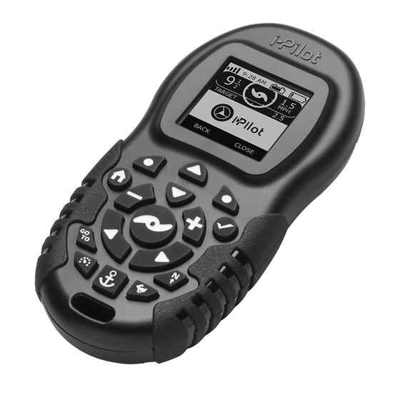
Page 7: Remote Buttons
REMOTE BUTTONS REMOTE BUTTONS MENU CONTROL BUTTONS Home Pressing this button will always bring you to the Home Screen. Press to accept menu selections. Press to power remote on. Press and hold for 3 seconds to power remote off. Left Softkey & Right Softkey Buttons change function based on the mode of operation and which screen is presently displayed. -
Page 8: Header & Iconography
HEADER & ICONOGRAPHY HEADER 10:50 A GPS Signal Strength 10:50 A Shows the level of GPS signal strength. If no bars appear, the system has not yet acquired a GPS fix. Time Motor Motor Battery Battery 10:50 A Displays motor battery level when prop is disengaged. GPS Signal Remote Strength... -
Page 9: Display Screen
DISPLAY SCREEN SAMPLE SCREENS Become familiar with some of the display screens used on the i-Pilot remote interface. iTracks Spot-Locks 10:50 A 10:50 A IT01 9:51 AM APR 27 SL01 9:51 AM APR 01 DIST 0.46 sm BRG 86° DIST 40 ft BRG 86°... -
Page 10: Getting Started
Navigation i-Pilot uses GPS satellite signals as well as compass data to know where it is, where its heading and the direction the motor is pointing. Since i-Pilot depends on GPS satellite signals for navigation, a minimum GPS signal of one bar is required in order for GPS navigation controls to be enabled. -
Page 11: System Startup
Fluctuating temperatures can lead to battery damage, such as capacity loss, leakage or rupture of batteries. Damaged batteries may damage your remote. Minn Kota recommends removing batteries from the remote when it is not expected to be used for extended periods of time, or for long-term storage, to avoid remote damage from the batteries. - Page 12 10:50 A display screen will turn on. A message about the safe and prudent operation of your vessel. i-Pilot operation will appear on the display screen. This product does not relieve you from the Use the Right Softkey to select OK.
-
Page 13: Audio Modes
AUDIO MODES The i-Pilot controller in the Control Head contains an internal speaker which can be configured to work in two different audio modes. The unit is factory set to Audio Mode 2. Review the modes below to determine what audio patterns are caused by conditions in each audio mode. - Page 14 AUDIO MODES c. Use the Left Softkey to select the Options Options Options menu. Autopilot Mode Language d. Use the Menu Up and Menu Down buttons Arrival Mode Time to find the Audio Mode menu. Use the Ok Prop Auto On Units button to select it.
-
Page 15: Spot-Lock
Arrival Circle, it will adjust the motor speed to zero. Outside forces such as wind and current will cause If i-Pilot sees the motor is outside of the circle, it will control the boat to move around the Arrival Circle. Spot-... - Page 16 BRG 43° SL04 7:34 AM APR 01 DIST 138 ft BRG 12° Back iTracks Due to safety reasons, i-Pilot will not re-engage a saved Spot-Lock location greater than a quarter mile away. 16 | minnkotamotors.com ©2016 Johnson Outdoors Marine Electronics, Inc.
- Page 17 Spot-Lock Jog Spot-Lock Jog is a feature that is only available when the i-Pilot controller is paired with a Heading Sensor. For information on the Heading Sensor, go to the "Heading Sensor" section of this manual. a. To engage Spot-Lock Jog, first engage...
-
Page 18: Cruise Control
WITH CRUISE CONTROL During regular operation of the i-Pilot navigational system, the user can control prop speed. The controller will communicate the speed over ground to the remote and the remote will display it. The speed over ground is the speed that the boat is traveling and will vary based on environmental factors such as wind and current, even if the prop speed remains the same. -
Page 19: Working With Cruise Control
CRUISE CONTROL WORKING WITH CRUISE CONTROL Engaging Cruise Control a. Press the Cruise Control button on the remote. 10:50 A b. The Target Speed will appear on the display screen. Press the Speed Down or Speed Up TARGET TARGET buttons to adjust the Target Speed. NOTE: If the Prop is not turning, be sure to Record... - Page 20 CRUISE CONTROL Jump To or Set a Cruise Control Preset a. To jump to or set a Cruise Control Preset, first 10:50 A 10:50 A engage Cruise Control. b. Use the Speed Down or Speed Up buttons TARGET TARGET TARGET TARGET to change the Target Speed.
-
Page 21: High Speed Bypass
HIGH SPEED BYPASS MOTOR SPEED AND HIGH SPEED BYPASS The Motor Speed with High Speed Bypass is set to 10 when engaged and returns to the previously set speed when disengaged. WARNING Watch for a turning propeller when High Speed Bypass is engaged. A turning propeller can cause injury. High Speed Bypass will automatically turn the prop on to Speed 10, even if the engagement is accidental. - Page 22 HIGH SPEED BYPASS Disengaging High Speed Bypass a. When High Speed Bypass is engaged, press the 10:50 A 10:50 A High Speed Bypass button on the remote to disengage High Speed Bypass. NOTE: Manually adjusting the speed below speed 10 will also disengage High Speed Bypass.
-
Page 23: Autopilot
WITH AUTOPILOT When in AutoPilot, i-Pilot keeps the trolling motor pointed in the direction you want to go. Each time the wind or water current moves the boat off course, the AutoPilot senses the change and steers itself back to the original heading. The AutoPilot direction is set every time a steering change is made. -
Page 24: Working With Autopilot
The Legacy AutoPilot or Advanced AutoPilot icon will display on the screen. c. To adjust the desired heading, manually steer 114° 120° the motor to the new heading. i-Pilot will automatically lock onto the new heading. Options System Options... - Page 25 AUTOPILOT To Set the Default AutoPilot Mode AutoPilot has two modes: 1. Legacy - This method of heading tracking does not take into account external forces such as a side wind or currents, which can allow side drift. 2. Advanced - Advanced AutoPilot not only uses compass heading but also GPS signal data to correct for cross winds, current and other external forces to keep the boat on an intended course.
-
Page 26: Itracks
UNDERSTANDING iTRACKS The i-Pilot system can be used to record sets of points that make up an iTrack. When recording an iTrack, i-Pilot starts to record GPS position data in the form of Track Points. The very first Track Point recorded is called the Start, and the last point recorded is called the End. -
Page 27: Working With Itracks
TRACKS WORKING WITH iTRACKS Recording An iTrack a. Use the Menu Up or Menu Down buttons iTracks 10:50 A until the menu at the bottom of the display screen IT01 9:51 AM APR 27 DIST 2.88 sm BRG 86° shows the Record menu. IT02 9:35 AM APR 14... - Page 28 WARNING NOTE: If there are no Spot-Locks or iTracks in range, Due to safety reasons, i-Pilot will not re-engage a saved the remote will state there are none in range. iTrack greater than a quarter mile away. c. Use the Menu Up...
-
Page 29: Itrack Arrival Modes
TRACKS iTRACK ARRIVAL MODES iTrack has three Arrival Modes: 1. Off - Once the boat has completed navigating the iTrack, the Prop will turn off. Off is the default Arrival Mode. 2. Spot-Lock - After the boat has completed navigating the iTrack, the system will go into Spot-Lock at the point where the iTrack is completed. -
Page 30: Heading Sensor
The Minn Kota Heading Sensor provides boat heading information to a Bluetooth compatible i-Pilot equipped Minn Kota motor. It contains a compass that senses the boat’s heading. The heading is used by the i-Pilot system for navigation features such as Spot-Lock Jog. -
Page 31: Installation
2. Pairing - The Heading Sensor can be paired with i-Pilot. While the Heading Sensor is attempting to pair, the LED will flash on and off twice per second for up to 20 seconds. If the Heading Sensor is successfully paired, normal operation will begin. - Page 32 HEADING SENSOR TOOLS AND RESOURCES REQUIRED • Drill • #2 Screwdriver • Awl or similar marking tool • 1/4” Drill Bit • 9/64” Drill Bit • Marine-grade Silicone INSTALLATION MOUNTING OPTIONS There are two options to install the Heading Sensor. Determine if the Power Cable for the Heading Sensor will pass below the mounting surface.
- Page 33 HEADING SENSOR e. Position the sensor so that the arrow on the Keel of Boat Arrow to cover is pointed toward the front of the boat in Front the direction of travel. The arrow needs to be Screw Holes parallel with the keel of the boat. CAUTION Failure to align the Heading Sensor correctly will result in incorrect compass readings.
- Page 34 HEADING SENSOR ITEM(S) NEEDED #1 x 2 h. Apply a marine-grade silicone caulk or sealant to both #8 - 18x1-1/2 screws (Item #1) as needed Screw to protect your boat from water damage. Using a #2 Screwdriver, mount the Heading Screw Sensor to the mounting location using the two screws.
- Page 35 HEADING SENSOR c. Double check the position of the Heading Sensor Screw so that the arrow on the cover is pointed toward Arrow to Holes Front the front of the boat in the direction of travel. The arrow needs to be parallel with the Keel of Boat keel of the boat.
- Page 36 HEADING SENSOR h. Using a #2 Screwdriver, mount the Heading Sensor to the mounting location using the two Screw screws. Hand tighten only. CAUTION Screw If the mounting surface is thin or made of a lightweight material, the mounting surface may need to be reinforced in order to support the Heading Sensor.
-
Page 37: Working With The Heading Sensor
As quickly as possible, begin to hold the Pair button on the i-Pilot Control Head. e. The i-Pilot Control Head will emit a beep pattern when the Heading Sensor is successfully paired. Pair Release the Pair button on the Control Head. - Page 38 The Heading Sensor calibration is initiated using either the i-Pilot or i-Pilot Link remote. Refer to the Owner’s Manual for your motor if you are unsure of the i-Pilot system that comes with your motor. The process of calibrating the Heading Sensor must occur while your boat is on the water.
- Page 39 HEADING SENSOR d. On the i-Pilot remote, use the Menu Up System 10:50 A Menu Down buttons to find the System menu About at the bottom of the display screen. Update So ware e. Use the Right Softkey to select the System Pair menu.
- Page 40 Offset will be a perfect 0° degrees. Knowing that installations are never perfect, the Heading Offset can be set on the i-Pilot remote to compensate for the difference between the two. Heading Offset has the ability to correct the difference in measurement in a range between +30°...
-
Page 41: Motor Controls
MOTOR CONTROLS To Toggle the Prop Auto On a. Press the Home button. 10:50 A 10:50 A b. Use the Menu Up and Menu Down buttons to find the Options menu at the bottom of the display screen. c. Use the Left Softkey to select the Options menu. - Page 42 Boat Scale. Thrust requirements are determined by the size and weight of your boat. Minn Kota suggests selecting a trolling motor with at least 2 lbs. of thrust for every 100 lbs. of boat weight when the boat is fully loaded with fuel, people, tackle, etc. This guide is established under normal lake fishing conditions and should be used as a general guide to determine how ideally the thrust of your trolling motor is matched to the weight of your boat.
- Page 43 MOTOR CONTROLS e. Use the Menu Up and Menu Down buttons Boat Scale to scroll to +2, +1, 0, -1, or -2. Use the Ok button to select the option highlighted. The circle to the right of the selected Boat Scale will become solid when selected. Back Close Deploying the Motor...
- Page 44 MOTOR CONTROLS Stowing the Motor a. Press the Home button. 10:50 A 10:50 A b. Use the Menu Up and Menu Down buttons to find the Stow menu at the bottom of the display screen. NOTE: The Stow menu at the bottom of the Record Lock Trim...
- Page 45 MOTOR CONTROLS Adjusting Trim a. Press the Home button. 10:50 A 10:50 A b. Use the Menu Up and Menu Down buttons to find the Trim menu at the bottom of the display screen. c. Use the Left Softkey to select the Trim menu. Trim Stow Record...
-
Page 46: Remote Controls
REMOTE CONTROLS To Adjust the Backlight Brightness a. Press the Home button. 10:50 A 10:50 A b. Use the Menu Up and Menu Down buttons to find the Options menu at the bottom of the display screen. c. Use the Left Softkey to select the Options menu. - Page 47 REMOTE CONTROLS To Adjust the Backlight Timeout a. Press the Home button. 10:50 A 10:50 A b. Use the Menu Up and Menu Down buttons to find the Options menu at the bottom of the display screen. c. Use the Left Softkey to select the Options menu.
- Page 48 About Boat Scale CAUTION Update So ware Sensor Cal Pair Sensor O set Boat Scale Restore Defaults This will restore the i-Pilot's factory settings! Back Close Back Close e. Use the Left Softkey to select the Restore option. CAUTION Caution: This Will Restore the Remote’s...
- Page 49 REMOTE CONTROLS c. Use the Left Softkey to select the Options Options Options menu. Sort Order Autopilot Mode d. Use the Menu Up and Menu Down buttons Backlight Arrival Mode to find the Language menu. Use the Ok button Auto O Prop Auto On to select it.
- Page 50 REMOTE CONTROLS e. Use the Menu Up and Menu Down buttons Units - Distance Units to find the Distance menu. Use the Ok button or sm Distance to select it. m or km Speed Use the Menu Up and Menu Down buttons or nm to scroll to the desired unit of measurement.
-
Page 51: Change The Time Zone
REMOTE CONTROLS Change the Time Format a. Press the Home button. 10:50 A 10:50 A b. Use the Menu Up and Menu Down buttons to find the Options menu at the bottom of the display screen. Record Lock Options System c. - Page 52 REMOTE CONTROLS c. Use the Left Softkey to select the Options Options Options menu. Autopilot Mode Backlight d. Use the Menu Up and Menu Down buttons Arrival Mode Auto O to find the Time menu. Use the Ok button to Prop Auto On Language select it.
- Page 53 REMOTE CONTROLS e. Use the Menu Up and Menu Down buttons Time Time to find the Daylight Savings menu. 12-Hour 12-Hour Use the Ok button to toggle the check box On 24-Hour 24-Hour and Off. Time Zone Time Zone Daylight Savings Daylight Savings NOTE: The displayed time will be adjusted for...
- Page 54 Auto O 15 Minutes WARNING 30 Minutes 60 Minutes When the motor is being controlled by the i-Pilot system, 90 Minutes the controller will continue to perform the last task it was Back Close assigned, even when the remote is not powered "on".
- Page 55 REMOTE CONTROLS To Lock and Unlock the Remote a. Press the Home button. 10:50 A 10:50 A b. Use the Menu Up and Menu Down buttons to find the Lock menu at the bottom of the display screen. NOTE: For all motors except the Ulterra Record Lock Unlock...
-
Page 56: I-Pilot App
Specifications subject to change without notice. This diagram is for reference only and may differ from your actual app interface. i-Pilot app will only work with i-Pilot enabled motors. Be sure that you download the correct app as other Minn Kota apps will not work with your motor. - Page 57 The App Update Indicator is only available when an update to the app is available. This icon will not appear when the app is up-to-date. This icon is for updates to the app only. For updates to the controller, refer to the "i-Pilot Software Update"...
- Page 58 WARNING The person operating the i-Pilot app is under the same responsibility of operation as if they were operating the i-Pilot either through the remote or any other manner. All safety considerations and precautions for motor operation must be heeded and abide by.
-
Page 59: Launching The App & Demo Mode
-PILOT APP LAUNCHING THE APP & DEMO MODE Launching the app when it is not paired with the motor will allow you to try it out. Every time the app is launched, you must agree with the disclaimer in order to continue. Become familiar with the app screens in order to understand how to operate your motor with the app. -
Page 60: Getting Started
Once you have successfully installed the app and verified installation, close the app to begin the pairing process. a. On the device you intend to pair with the i-Pilot Control Head - Ulterra & Riptide Ulterra controller, turn Bluetooth "on". - Page 61 -PILOT APP Update the i-Pilot App NOTE: It is important to keep the i-Pilot App up-to-date, because all updates to the i-Pilot remote and controller are communicated through the app. a. Open the i-Pilot app on the device. Check to see if the App Update Indicator icon in the upper right hand corner is present.
- Page 62 Check Remote and Controller Software Version The i-Pilot App on the device communicates with the i-Pilot controller, which is in the Control Head of the paired motor. When the App is communicating with a controller, the About screen will display the current version of the app and information about the versions of software in the controller.
- Page 63 -PILOT APP Update the i-Pilot Controller In order to update the i-Pilot controller, the i-Pilot app on the NOTE: The i-Pilot remote must be updated from the device should first be updated. To update the app, please refer controller, using the remote. Complete any remote to the "Update the i-Pilot App"...
-
Page 64: Service & Maintenance
SERVICE & MAINTENANCE BATTERY REPLACEMENT TOOLS AND RESOURCES REQUIRED • #1 Phillips Screwdriver INSTALLATION a. Disconnect the Motor from the battery or make 10:50 A sure that the Remote is out of range from the receiver before replacing the remote batteries. b. -
Page 65: I-Pilot Software
Be sure that the software in the Controller is updated before updating the remote. Please see 10:50 A 10:50 A the "i-Pilot App" section of this manual on how to update the Controller. NOTE: The software update for the remote will come from the Controller. -
Page 66: Pairing A Remote With A Controller
PAIRING A REMOTE An i-Pilot controller may pair up to 3 remotes. These three remotes can be a combination is standard i-Pilot remotes and Micro remotes. Any additional remotes can be paired using the following steps. Once the maximum number of remotes have been paired, the controller will start replacing a new remote with the oldest paired remote in memory. - Page 67 SERVICE & MAINTENANCE c. Use the Right Softkey to select the System System System menu. About About d. Use the Menu Up and Menu Down buttons Update So ware Update So ware to find the Pair option. Pair Pair Boat Scale Boat Scale e.
-
Page 68: General Maintenance
4. i-Pilot won’t let me turn on certain features like: Advanced AutoPilot, Record, GO TO, Cruise Control or Spot-Lock. • Verify that the GPS Signal Strength icon on the LCD shows at least one bar. If there are no bars, i-Pilot will not allow these GPS-based features to be enabled. -
Page 69: Frequently Asked Questions
Orders after 12 noon central time will ship the next business day if in stock. Frequently Asked Questions We have FAQs available on our website to help answer all of your Minn Kota questions. Visit minnkotamotors.com click on “Frequently Asked Questions”... -
Page 70: Compliance Statements
Minn Kota motors are not subject to the disposal regulations EAG-VO (electric devices directive) that implements the WEEE directive. Nevertheless never dispose of your Minn Kota motor in a garbage bin but at the proper place of collection of your local town council. -
Page 71: Fcc Compliance
• Maximum RF power transmitted: +10 dBm TRADEMARKS Minn Kota®, Riptide®, i-Pilot®, AutoPilot™, CoPilot™, Link™, PowerDrive™, Terrova™, Ulterra™ are trademarked by or registered trademarks of Johnson Outdoors Marine Electronics, Inc. The Bluetooth® word mark and logos are registered trademarks owned by Bluetooth SIG, Inc. and any use of such marks by Johnson Outdoors Inc is under license. -
Page 72: Parts Diagram & Parts List
POWERDRIVE, RIPTIDE POWERDRIVE, TERROVA, RIPTIDE TERROVA, ULTERRA, RIPTIDE ULTERRA & ULTREX The parts diagram and parts list provides Minn Kota® WEEE compliance disassembly instructions. For more information about where you should dispose of your waste equipment for recycling and recovery and/or your European Union member state requirements, please contact your dealer or distributor from which your product was purchased. - Page 73 PARTS DIAGRAM & PARTS LIST Remote & Heading Sensor Parts List Assembly Part # Description Quantity 2994075 REMOTE ASY, IPILOT 2996400 HEADING SENSOR ASSEMBLY 2882557 CASE BTM, WINDOW ASM & VENT DCL 2886423 BATTERY DOOR, SEAL, SCREW KIT Item Part # Description Quantity 2373443...
- Page 74 PARTS DIAGRAM & PARTS LIST i-PILOT CONTROL HEAD Control Head Parts Diagram Ultrex, Terrova & Riptide Terrova PowerDrive & Riptide PowerDrive Ulterra & Riptide Ulterra 74 | minnkotamotors.com ©2016 Johnson Outdoors Marine Electronics, Inc.
- Page 75 DECAL, CTRL BOX SIDE BT SW *SALTWATER* *RIPTIDE ULTERRA* *RIPTIDE TERROVA* DECAL, DOMED IPILOT FW *FRESHWATER* *ULTERRA* *I-PILOT* *POWERDRIVE* *ULTREX* 2395520 *TERROVA* DECAL, DOMED IPILOT SW *SALTWATER* *RIPTIDE ULTERRA* *I-PILOT* *RIPTIDE TERROVA* 2395521 *RIPTIDE POWERDRIVE* CTRL HEAD ASY, IPILOT 1.6 ULT *FRESHWATER* *ULTERRA* ✖...
-
Page 76: Minnkotamotors.com
Stop buying new batteries and start taking care of the ones you’ve got. Many chargers can actually damage your battery over time – creating shorter run times and shorter overall life. Digitally controlled Minn Kota chargers are designed to provide the fastest charge that protect and extend battery life.
Need help?
Do you have a question about the i-Pilot and is the answer not in the manual?
Questions and answers