Table of Contents
Advertisement
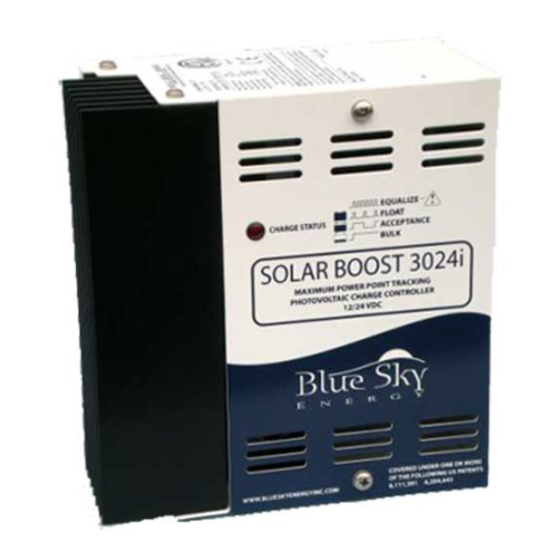
SOLAR BOOST™ 3024i
30AMP 12/24VDC MAXIMUM POWER POINT TRACKING
PHOTOVOLTAIC CHARGE CONTROLLER
INSTALLATION AND OPERATION
MANUAL
THIS MANUAL INCLUDES IMPORTANT SAFETY INSTRUCTIONS FOR
MODEL SB3024i. SAVE THESE INSTRUCTIONS.
COVERED UNDER ONE OR MORE OF THE FOLLOWING US PATENTS
6,111,391 • 6,204,645
© Blue Sky Energy, Inc. 2005
430-0018 C
Advertisement
Table of Contents

Related Manuals for Blue Sky Energy SOLAR BOOST 3024i


Summary of Contents for Blue Sky Energy SOLAR BOOST 3024i
- Page 1 PHOTOVOLTAIC CHARGE CONTROLLER INSTALLATION AND OPERATION MANUAL THIS MANUAL INCLUDES IMPORTANT SAFETY INSTRUCTIONS FOR MODEL SB3024i. SAVE THESE INSTRUCTIONS. COVERED UNDER ONE OR MORE OF THE FOLLOWING US PATENTS 6,111,391 • 6,204,645 © Blue Sky Energy, Inc. 2005 430-0018 C...
-
Page 2: Table Of Contents
Blue Sky Energy - Solar Boost 3024i TABLE OF CONTENTS IMPORTANT SAFETY INSTRUCTIONS ..................... 2 PRODUCT DESCRIPTION ........................3 Part Numbers and Options..................... 3 OPERATION ............................3 Optional Remote Displays...................... 3 Charge Status Indicator ......................4 Three Stage Charge Control ....................4 Bulk Charge...................... -
Page 3: Important Safety Instructions
Installation and Operation Manual IMPORTANT SAFETY INSTRUCTIONS This manual contains important instructions for Model SB3024i SAVE THESE INSTRUCTIONS 1. Refer installation and servicing to qualified service personnel. High voltage is present inside unit. Incorrect installation or use may result in risk of electric shock or fire. No user serviceable parts in this unit. 2. -
Page 4: Product Description
Solar Boost™ 3024i a 30 amp 12/24 volt Maximum Power Point Tracking (MPPT) photovoltaic (PV) battery charge controller. Through the use of patented MPPT technology, Solar Boost 3024i can increase charge current up to 30% or more compared to conventional controllers. Solar Boost 3024i’s sophisticated three stage charge control system can be configured to optimize charge parameters to precise battery requirements. -
Page 5: Charge Status Indicator
Bulk Charge When charge starts the Solar Boost 3024i attempts to apply the Acceptance charge voltage to the battery. The system will switch to Bulk charge if the battery is sufficiently discharged and/or insufficient charge current is available to drive the battery up to the Acceptance voltage setpoint. -
Page 6: Acceptance Charge
TWO STAGE CHARGE CONTROL Certain battery types or system configurations may require two stage charge control. Solar Boost 3024i can be configured for a two stage bulk-acceptance charge to accommodate these batteries or systems. Two stage charge is selected by setting the Float charge voltage setting to No Float. -
Page 7: Manual Equalization
The factory defaults of 15.5/31.0V can be changed using the IPN-ProRemote. Regardless of what setpoint values are entered by the user or result from temperature compensation, the Solar Boost 3024i will never attempt to apply a charge voltage greater than the maximum voltage setpoint limit value. -
Page 8: How Mppt Works
Solar Boost 3024i is fully protected against reverse polarity and high voltage transients for both the PV and the battery connections. If the battery is connected reverse polarity, Solar Boost 3024i will not operate. If the PV array is connected reverse polarity the charge control system will not turn on or provide output current. -
Page 9: Solar Boost 3024I Setup
FIGURE 3 SOLAR BOOST 3024i SETUP Solar Boost 3024i has various setup parameters all of which are preconfigured at the factory. Most installations require no changes other than configuring the Auxiliary Output if used, and enabling Equalization if desired. Default settings are typically suitable for most flooded lead-acid batteries. -
Page 10: Basic Settings
Restoring Factory Default Settings Factory defaults can be easily restored into the Solar Boost 3024i. If the unit is not received in a factory sealed package, it is possible that settings may not be set to factory defaults. If there is any doubt about present settings, restoring defaults is highly recommended. -
Page 11: Charge Mode
Charge Mode Solar Boost 3024i is typically configured for three stage charge. Certain battery types or system configurations may benefit from two stage constant voltage charge. Two stage charge is selected by setting the Float voltage setting to one step below it’s minimum voltage setting. -
Page 12: Battery And Pv Wiring
Bat– and PV– connect together internally. Wiring requirements for Solar Boost 3024i are somewhat different than conventional PV controllers. While the performance of other controllers may be affected somewhat by wiring, wiring and connections used with this unit can have a significant effect on current boost performance. -
Page 13: Auxiliary Output
Installation and Operation Manual AUXILIARY OUTPUT CAUTION: The auxiliary output can serve one of two functions, either a 2 amp auxiliary battery charger, or a 20 amp load controller. It cannot perform both auxiliary battery charge and load control functions at the same time. -
Page 14: Installing A Multi-Controller System
Blue Sky Energy - Solar Boost 3024i INSTALLING A MULTI-CONTROLLER SYSTEM Up to 8 IPN based charge controllers can be connected together in a multi-controller system charging a common battery. In an IPN based multi-controller system the controllers will setup and operate as a single machine rather than separate charge controllers. -
Page 15: Mounting
Installation and Operation Manual MOUNTING CAUTION: Mount the unit with heatsink fins oriented vertically and do not enclose in a confined space. If not mounted vertically, average output power may be reduced to prevent damage due to over temperature. The unit is not watertight and must be protected from rain, snow and excessive moisture. DETAILED DIMENSIONAL DRAWING FIGURE 6... -
Page 16: Troubleshooting Guide
Blue Sky Energy - Solar Boost 3024i TROUBLESHOOTING GUIDE SYMPTOM PROBABLE CAUSE ITEMS TO EXAMINE OR CORRECT Completely dead, No battery power Battery disconnected, overly discharged, or connected reverse no display polarity. Battery powers the system, not PV. Unit will not turn PV disconnected PV must supply at least 0.25A at 2V more than battery voltage to... - Page 17 Installation and Operation Manual SYMPTOM PROBABLE CAUSE ITEMS TO EXAMINE OR CORRECT Auxiliary battery Auxiliary output not configured for Confirm dip switch #4 is OFF. not charging auxiliary battery charge Primary battery not highly charged Auxiliary battery will not receive charge unless primary battery is highly charged in Acceptance or Float.
-
Page 18: Specifications
Blue Sky Energy - Solar Boost 3024i SPECIFICATIONS SPECIFICATIONS Solar Boost 3024i Output Current Rating 30 Amp maximum, automatic 30 Amp current limit Nominal Battery Voltage 12 / 24VDC PV Input Voltage 57VDC maximum Power Consumption 0.35W Typical standby • 1.0W Typical charge on ➁... -
Page 19: Two Year Limited Warranty
TWO YEAR LIMITED WARRANTY Blue Sky Energy, Inc. (hereinafter BSE), hereby warrants to the original consumer purchaser, that the product or any part thereof will be free from defects due to defective workmanship or materials for a period of two (2) years subject to the conditions set fourth below.
Need help?
Do you have a question about the SOLAR BOOST 3024i and is the answer not in the manual?
Questions and answers