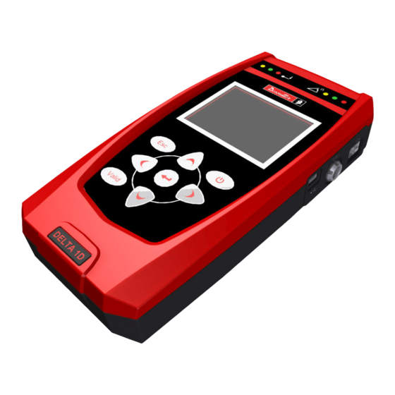
Table of Contents

Advertisement

To reduce the risk of injury, before using or servicing tool, read and understand
the following information.
The features and descriptions of our products are subject to change without
prior notice.
1
249
(
)
DELTA – User Guide
WARNING
Part Number
6159938880
Issue
13
Date
01/2018
Page
1 / 249
01/2018

Advertisement

Table of Contents
loading
Need help?

Need help?

Do you have a question about the Delta 1D and is the answer not in the manual?

Questions and answers

Subscribe to Our Youtube Channel

Summary of Contents for Desoutter Delta 1D

  • Page 1 Part Number 6159938880 Issue Date 01/2018 Page 1 / 249 DELTA – User Guide WARNING To reduce the risk of injury, before using or servicing tool, read and understand the following information. The features and descriptions of our products are subject to change without prior notice.
  • Page 2: October

    Part Number 6159938880 Issue Date 01/2018 Page 2 / 249 Revision history Minimum Ref. firmware Issue Date Description DeltaQC version version 04 January 2012 First issue 1.0x 2.0.x General manual review, added Q54000 13 November statistic, DRT added for quality tests, test 1.1x 2.2.x 2012...
  • Page 3: Table Of Contents

    Specifications ......................11 EC Declaration of Conformity .................. 14 SYSTEM OVERVIEW ................... 15 Delta Models ......................16 2.1.1 Delta 1D (P/N 6159351010) ................... 16 2.1.2 Delta 6D (P/N 6159351020) ................... 17 2.1.3 Delta 7D (P/N 6159351470) ................... 17 Presentation ......................18 2.2.1...
  • Page 4 Track ........................79 6.1.2 Peak ........................80 6.1.3 Tachometer ......................81 6.1.4 Tightening ....................... 82 USE OF DELTA 1D ....................83 Testing a Tool ......................84 7.1.1 Test setup ....................... 85 Delta 1D Settings ....................85 7.2.1 Display Language ....................85 7.2.2...
  • Page 5 Part Number 6159938880 Issue Date 01/2018 Page 5 / 249 8.3.1 CVI II calibration function ..................111 8.3.2 CVI3 calibration function ..................113 8.3.3 CVIC II calibration function ................... 115 Delta 6D/7D Settings .................... 117 8.4.1 Display language ....................117 8.4.2 Date and Time ......................
  • Page 6 Part Number 6159938880 Issue Date 01/2018 Page 6 / 249 15.1.4 K value ........................172 15.1.4.1 K value evaluation ................... 172 TOOL CHECK: FREE ANGLE TEST ..............174 16.1 Test Setup for Free Angle Test ................174 QUALITY TEST ON JOINTS ................176 17.1 Residual Torque/Angle ..................
  • Page 7 Part Number 6159938880 Issue Date 01/2018 Page 7 / 249 24.2 Angle Correction Coefficient ................. 238 24.3 Correction Formulas ..................... 240 SCHEDULED MAINTENANCE ................241 25.1 Cleaning ....................... 241 25.2 Battery Pack Maintenance ..................241 TROUBLESHOOTING GUIDE ................242 26.1 Delta Diagnostic....................243 DELTA FACTORY SETTINGS ................
  • Page 8: Safety Information

    Part Number 6159938880 Issue Date 01/2018 Page 8 / 249 SAFETY INFORMATION WARNING: PLEASE CAREFULLY READ THE DELTA SAFETY INFORMATION (No. 6159920590) PRIOR TO USE THE PRODUCT AND PAY ATTENTION TO THE SAFETY INSTRUCTIONS PROVIDED. 01/2018...
  • Page 9: Batteries Information According To European Regulation 2006/66/Ec

    Part Number 6159938880 Issue Date 01/2018 Page 9 / 249 BATTERIES INFORMATION ACCORDING TO UROPEAN 2006/66/EC REGULATION BATTERY SPECIFICATION TYPE: Lithium-ion, 3.75 V 6.8 Ah WEIGHT: 155 g The battery is installed on the back side of the Delta (refer to the picture below): NOTE: Once removed, the wasted batteries must be dismissed according to local regulations.
  • Page 10: Introduction

    Chapter 6 Getting started with Delta test. This part is dedicated to the specific main menu and Use of the Delta 1D Chapter 7 settings of the Delta 1D. Use of the Delta 6D and This part is dedicated to the specific main menu and Chapter 8 settings of the Delta 6D/7D.
  • Page 11: Specifications

     Torque range: it is defined by the transducer connected to the Delta.  Angle measurement (only for Delta 6D/7D models)  Results memory capacity: 1000 test results for Delta 1D; 5000 test results for Delta 6D/7D  Curves memory capacity: 10 ...
  • Page 12  Recharging: max. 8 hours DIMENSIONS AND WEIGHT Dimensions are in mm. Weight: 500 g NOTE: The Delta 1D / 6D / 7D have the same dimensions and weight. For further differences between these models, refer to the paragraph “Delta Models”. 01/2018...
  • Page 13: Part Number 6159938880 Issue

    Part Number 6159938880 Issue Date 01/2018 Page 13 / 249 ENVIRONMENTAL The following conditions must be observed during operation:  Internal Use only  Environmental Class: II  IP Index according to IEC 60529: IP40  Room Temperature: 5 to 40°C ...
  • Page 14: Ec Declaration Of Conformity

    Part Number 6159938880 Issue Date 01/2018 Page 14 / 249  Display: 800 x 600, 256 colors (1024 x 768, High Color (16-bit) recommended)  Operating Systems: Windows XP SP3, Windows 7, Windows 8, Windows 8.1, Windows 10  Internet Explorer 5.01 or later (required for installation of the .NET Framework) ...
  • Page 15: System Overview

    Transducers DeltaQC Delta The Delta 1D/6D/7D are instruments designed for optimal operations in:  Tools testing: The Delta offers a set of tests for evaluating click-wrenches, slip-wrenches, nutrunners and pulse tools, measuring the torque values and producing results with statistical parameters.
  • Page 16: Delta Models

    Quick test mode of the Delta6D/7D is equal to the operation mode of the Delta1D 2.1.1 Delta 1D (P/N 6159351010) The Delta 1D provides a demo mode menu (track or peak functions) and the test function of wrenches, nutrunners and pulse tools. The measurements are made only in torque.
  • Page 17: Delta 6D (P/N 6159351020)

    Part Number 6159938880 Issue Date 01/2018 Page 17 / 249 2.1.2 Delta 6D (P/N 6159351020) The Delta 6D provides a quick test menu (track, peak and tachometer functions) and the test of wrenches, nutrunners and pulse tools. The quick test menu provides also a set of predefined test for wrenches, nutrunners and pulse tools, to start a test in few steps.
  • Page 18: Presentation

    Part Number 6159938880 Issue Date 01/2018 Page 18 / 249 Presentation The Delta consists of the following parts: Delta controller The main part that contains all the hardware and firmware. It is provided with battery. External power supply (P/N 6159361430) The external power supply is mainly used for battery recharge.
  • Page 19 Part Number 6159938880 Issue Date 01/2018 Page 19 / 249 The following accessories can be also ordered: Delta rubber protection P/N 6159361410 Rubber protection recommended to protect the device. Cable for transducers 2m length P/N 6159174300 Cable to connect the Delta to the DRT, DST, DWT, DWTA, DLT and PST. Cable for transducers 5m length P/N 6159174330 Cable to connect the Delta to the DRT, DST, DWT, DWTA, DLT and PST.
  • Page 20 Part Number 6159938880 Issue Date 01/2018 Page 20 / 249 The Delta is ready for working either by connecting the power supply or inserting a charged battery. It is characterized by the following features: Connector for transducers Barcode reader (only for Delta 7D) LEDs Network External power...
  • Page 21: Battery

    Part Number 6159938880 Issue Date 01/2018 Page 21 / 249 2.2.1 Battery The Delta can operate powered either by its battery pack or by the external power supply. NOTE: The rechargeable Lithium-ion battery ensures over 16 hours of operating time. 3.
  • Page 22: External Power Supply

    Delta. External power supply connector AC power WARNING: Use only the power supply ordered from Desoutter. Warranty will not cover damages to the Delta caused by the use of a different external power supply. 2.2.3 Delta clip The clip can be fixed on the operator trousers. The Delta can be easily attached and removed from the clip.
  • Page 23: Adapters For Analog Transducers

    Custom transducers) to the To Delta Delta. To connect the adapter to the Delta, use the same cable for connecting the Desoutter digital transducers: NOTE: Refer to the paragraph “Transducers” for further details. The following tables show the transducer connector pin-out (to connect a custom transducer) for all of...
  • Page 24 Part Number 6159938880 Issue Date 01/2018 Page 24 / 249 P/N 6159176710 - ART 4, CMD and ST 4000 Adapter Description + 5V Torque excitation - 5V Torque excitation + Torque signal - Torque signal Ground /shield Not connected P/N 6159176740 – GSE 2500 Adapter P/N 6159176750 –...
  • Page 25: User Interfaces

    Part Number 6159938880 Issue Date 01/2018 Page 25 / 249 USER INTERFACES Transducer Connector Connector for transducers The ten pins connector is available to connect the transducers to the Delta. The connector pin-out is as follows: Description Description MOSI - 15 V (- Mains supply) CLOCK CDE.
  • Page 26: Leds

    Part Number 6159938880 Issue Date 01/2018 Page 26 / 249 LEDs Two set of three LEDs provides information about the ongoing test. One set is dedicated for the torque result, while the other is dedicated for the angle result (and thus it is not active for the Delta 1D).
  • Page 27: Keyboard

    Part Number 6159938880 Issue Date 01/2018 Page 27 / 249 Keyboard Use the keyboard to browse the Delta menu: Icon Name Description Switch on the Delta. ENTER Enter menu. RIGHT Explore curve. Up (browse menu), increase value in settings menus. Down (browse menu), decrease DOWN value in settings menus.
  • Page 28: Ethernet Port

    Delta with the DeltaQC software. It is also possible to export test results on the Ethernet port. Network port NOTE: The Delta 1D does not support the Ethernet connection. Refer to the paragraph “Connecting with the Delta” for further details. Mini USB Port The USB port is available for programming the Delta with DeltaQC software.
  • Page 29: Working With "Delta Qc" Software

    Part Number 6159938880 Issue Date 01/2018 Page 29 / 249 WORKING WITH “DELTA QC” SOFTWARE USB or Excel file Network Printer Delta QC Delta DeltaQC is a PC software package developed to manage the Delta. It offers easy user-friendly programming and real time monitoring of the instrument. DeltaQC serves as an interface between the user and the Delta.
  • Page 30 Part Number 6159938880 Issue Date 01/2018 Page 30 / 249 If DeltaQC is already installed on the PC and it is characterized by a version equal to 3.4.6 (or previous), BEFORE executing the new setup, it is MANDATORY uninstalling the previous version by acting on the control panel as explained in the following procedure: ...
  • Page 31 Part Number 6159938880 Issue Date 01/2018 Page 31 / 249  To uninstall (or change) programs on the PC, click on “Programs and Features” (refer to the above screen). The following screen is displayed: Select “DeltaQC” from the list. Click on the right button of the mouse and finally select “Uninstall” in order to uninstall DeltaQC from the PC.
  • Page 32 Part Number 6159938880 Issue Date 01/2018 Page 32 / 249 If DeltaQC is either not installed or already installed on the PC and it is characterized by a version equal to 3.4.8 (or later), execute the new setup. NOTE: For the operating systems Windows 7, Windows 8, Windows 8.1 and Windows 10, run the executable file by clicking on the right button of the mouse and selecting “Run as administrator”.
  • Page 33 Part Number 6159938880 Issue Date 01/2018 Page 33 / 249 In the second case, after inserting the USB key (refer to the figure on the right) in the PC, the following pop-up is shown (according to Autoplay Settings set on the PC): Double-click on “Open folder to view files”...
  • Page 34 Part Number 6159938880 Issue Date 01/2018 Page 34 / 249 Click “Run StartCD.vbs” and wait for the following window: ReadMe Install Install DeltaQC Software Firstly, click and read the ReadMe file, containing information about the installation. Then click on Install in order to start the installation wizard for the DeltaQC Software.
  • Page 35 01/2018 Page 35 / 249 Contact US It shows the Desoutter contact details. Register DeltaQC Software It provides the website link to register the DeltaQC Software. Registration must be executed after the installation. Refer to the end of this chapter for further software registration details.
  • Page 36 Part Number 6159938880 Issue Date 01/2018 Page 36 / 249 Follow the installation steps described below: This message is shown according to the User Account Control settings 01/2018...
  • Page 37 Part Number 6159938880 Issue Date 01/2018 Page 37 / 249 Default installation folder Enter Name and (recommended) Company/Organization 01/2018...
  • Page 38 Part Number 6159938880 Issue Date 01/2018 Page 38 / 249 If SQLServer2014 Express Edition is not installed in the PC, the following window alerts the user that it needs to be installed. A shortcut to SQLServer2014 Express Edition setup is automatically created on the desktop. NOTE: It is recommended to install the SQLServer2014 Express Edition at the end of the DeltaQC Software installation.
  • Page 39 Part Number 6159938880 Issue Date 01/2018 Page 39 / 249 While Microsoft SQL Server 2014 processes the current operation, the “process icon” (see the icon on the left) replaces the “setup icon” above mentioned on the toolbar. 1. Select 2. Select “New SQL Server “Installation”...
  • Page 40 Part Number 6159938880 Issue Date 01/2018 Page 40 / 249 If the PC is not connected, this screen is displayed. Click on Next to continue the SQLServer2014 Express Edition setup installation procedure After carefully reading the License terms, check the box “I accept the license terms” to continue the SQLServer2014 Express Edition setup installation procedure 01/2018...
  • Page 41 Part Number 6159938880 Issue Date 01/2018 Page 41 / 249 Select the Express feature to be installed Specify the name and instance ID for the instance of SQL Server. Instance ID becomes part of the installation path 01/2018...
  • Page 42 Part Number 6159938880 Issue Date 01/2018 Page 42 / 249 01/2018...
  • Page 43 Part Number 6159938880 Issue Date 01/2018 Page 43 / 249 SQL Server 2014 installation is completed successfully. Click on Close After clicking on Close key, the following screen is shown: Close button Click on Close button placed on the right upper corner of the above screen in order to close the “SQL Server installation Center”...
  • Page 44 Select and delete the highlighted items After installing DeltaQC Software, the program is added to the Start → Program → Desoutter → DeltaQC menu (a desktop icon is created as well). NOTE: The first time DeltaQC Software is executed, it is MANDATORY to register it (refer to the paragraph “Software registration”...
  • Page 45: Software Registration

    Part Number 6159938880 Issue Date 01/2018 Page 45 / 249 4.1.1 Software registration The first time DeltaQC Software is executed, the following window is shown: Public KEY Continue in demo mode Click to register Registration instructions Click on Continue in demo mode to skip the registration and working in demo mode (the registration can be done later).
  • Page 46 Part Number 6159938880 Issue Date 01/2018 Page 46 / 249 Create a new account, if it is not created yet: Submit Enter the own information and click Submit. The following confirmation message is shown: On the email address given in the account above, a link is sent. Click the link provided. Click “home”...
  • Page 47 Click “home”; now it is possible to login: Login On the following window, select License Management (from the same window it is possible either to edit the profile information or to open the Desoutter contact form): License management Edit profile...
  • Page 48 Part Number 6159938880 Issue Date 01/2018 Page 48 / 249 Click Submit; the following window is shown: Click either on Add to proceed with the registration or on Delete to delete the serial number and key already entered. After clicking on Add, the following screen is shown: Public key PC name 01/2018...
  • Page 49 Part Number 6159938880 Issue Date 01/2018 Page 49 / 249 Enter the Public key generated by the DeltaQC Software registration form and the PC name (choose any name) and click on Submit to get the registration code: Registration code Copy the above Registration code in the DeltaQC registration form and click on “Register” to complete the registration: Enter the Registration code...
  • Page 50: Deltaqc "Evaluation Version

    Part Number 6159938880 Issue Date 01/2018 Page 50 / 249 DeltaQC “Evaluation version” 4.1.2 If DeltaQC Software is not registered after the installation, it works as Evaluation for 90 days; the Evaluation version provides all the functionalities of the registered version. When the trial period expires, the software turns into “Free”...
  • Page 51: License Verification

    Part Number 6159938880 Issue Date 01/2018 Page 51 / 249 4.1.5 License Verification To verify the license installed, enter the DeltaQC Software and click on “About” placed in the Menu List: Menu List The DeltaQC version information is shown: License information 01/2018...
  • Page 52: Deltaqc Software Upgrade

    Part Number 6159938880 Issue Date 01/2018 Page 52 / 249 4.1.6 DeltaQC software upgrade In case a new version of DeltaQC Software is available, the new installation wizard automatically overwrites and upgrades the previous one. In case of the new version features a new database structure, the first time the new version is launched a database migration wizard is automatically started.
  • Page 53: Deltaqc Overview

    Part Number 6159938880 Issue Date 01/2018 Page 53 / 249 DeltaQC Overview Click on the DeltaQC icon to launch the software. The following main menu is shown: Menu list Toolbar Offline mode Online mode Assembly Line details area Assembly Line area Build area Log area Status bar...
  • Page 54 Part Number 6159938880 Issue Date 01/2018 Page 54 / 249 The areas shown in the main menu (refer to the above picture) can be customized; select View to define which areas enable or disable: The areas listed in “View” are as follows: Build area Enable/disable the Build area.
  • Page 55: Search Function

    Part Number 6159938880 Issue Date 01/2018 Page 55 / 249 4.2.1 Search function The DeltaQC is characterized by a search function, available to search the various items (Psets, Tools, Transducers and Routes) displayed in the Assembly Line area; in the following example, it is shown the Assembly Line/Pset area with the relative Search function: Items to be searched Search function...
  • Page 56: Menu List

    Part Number 6159938880 Issue Date 01/2018 Page 56 / 249 4.2.2 Menu list The following options are available in the DeltaQC Menu List: Illustration Name Description File The Exit option allows the user to exit from the Delta QC software. View The View option selects the areas to show/hide in the main menu.
  • Page 57: Toolbar

    Part Number 6159938880 Issue Date 01/2018 Page 57 / 249 4.2.3 Toolbar The toolbar icons are shortcuts to the basic functions in DeltaQC. Icon Icon name Description Save This icon saves the items (for example Pset or Tool) that are defined in the Assembly Line area.
  • Page 58: Status Bar

    Part Number 6159938880 Issue Date 01/2018 Page 58 / 249 4.2.4 Status bar Software version The status bar provides the connection status between the PC and the Delta. The battery icon shows the battery level:  Green: Battery level over 50% ...
  • Page 59: Transfer Online Data To The Database

    Part Number 6159938880 Issue Date 01/2018 Page 59 / 249 Click on the minus or plus symbols to close and open menus, and double click on function names to open the corresponding function. NOTE: Refer to the paragraph “Use of Delta 6D and 7D” to view in details how to create and setup a test program for Delta 6D/7D.
  • Page 60 Part Number 6159938880 Issue Date 01/2018 Page 60 / 249 Psets and tools marked as new can be added here to a Route (refer to the paragraph “Offline mode” for further details): Add to New items Route The “Add to Route” command is available only if there is a relevant Route for the new Pset/Tool. In the figure above only the first six Psets can be added to a Route.
  • Page 61: Settings In Deltaqc

    The connection between the DeltaQC and the Delta can be done either via USB or Ethernet (Ethernet is not available for Delta 1D model). The USB connection can be done easily with the USB cable between the PC and the instrument.
  • Page 62 Part Number 6159938880 Issue Date 01/2018 Page 62 / 249 After connecting the Delta to the PC with the DeltaQC software for the first time, select Scan (refer to the screen below): Scan After clicking on Scan, the following screen is shown: Click on Scan After clicking on Scan, select the available Delta...
  • Page 63 Part Number 6159938880 Issue Date 01/2018 Page 63 / 249 After the first time, perform the following steps:  Launch the DeltaQC software.  Turn on the Delta and wait for the Delta for its startup (the main menu is shown on the display). ...
  • Page 64: Ethernet Connection

    The Ethernet connection can be done either by using a network cable between the PC and the Delta 6D/7D or by connecting both of them to the same network. NOTE: The Ethernet connection is not available for the Delta 1D. Delta must be configured with the network parameters.
  • Page 65 Part Number 6159938880 Issue Date 01/2018 Page 65 / 249 After clicking on “Ethernet configuration” option, the following screen is shown: Set the parameters as follows: Port Set any port available in the own system. IP Address, Subnet mask Set valid parameters according with the own network (or PC network and Default gateway parameter if the Delta is directly connected to the PC).
  • Page 66 Part Number 6159938880 Issue Date 01/2018 Page 66 / 249 To open and possibly modify the list of Delta devices, select the Option → List of available devices… menu: After clicking on “List of available devices…”, the following screen is shown: Create a new file containing a list of devices.
  • Page 67: Delta Log File

    Part Number 6159938880 Issue Date 01/2018 Page 67 / 249 When the Delta is connected, the Connect icon is disabled, the Disconnect icon is active, and the Delta data are shown: Online mode Disconnect icon Online mode Delta LOG file The Log viewer function displays information about the Delta –...
  • Page 68 Log message(s) A “Log file” is automatically created in a subfolder of the installation directory of the DeltaQC software (typically: C:\Program Files\Desoutter\DeltaQC\Log). NOTE: A new file is created each day the software is used; the old files can be deleted.
  • Page 69: Transducers

    Part Number 6159938880 Issue Date 01/2018 Page 69 / 249 TRANSDUCERS Connect the Delta to one of the following transducers: DWT (only the Delta DWTA (only the 7D model supports Delta 7D model the DWT) supports the DWTA) When connecting a transducer, the Delta automatically detects it, and executes the proper zeroing. By selecting the Transducer →...
  • Page 70 Part Number 6159938880 Issue Date 01/2018 Page 70 / 249 In the Transducer info are detailed the transducers characteristics: In addition, two additional fields indicate if the transducer has been overloaded during the use with the Delta:  Max. Torque: Maximum torque applied to the transducer during the use with the Delta. If this value is over the Damage Limit, a warning message is shown for few seconds when the transducer is connected to the Delta;...
  • Page 71 Part Number 6159938880 Issue Date 01/2018 Page 71 / 249 A report of the transducer connected to the Delta can be obtained also from the Transducer → Connected transducer of the DeltaQC software: Report In case a DLT transducer is connected, this screen is as follows: 01/2018...
  • Page 72 Part Number 6159938880 Issue Date 01/2018 Page 72 / 249 The measurement unit is Newton (N). In addition, the following fields are shown:  Screw lubricant – tightening counter: This field counts the number of tightenings performed by the transducer connected to the Delta ...
  • Page 73 Part Number 6159938880 Issue Date 01/2018 Page 73 / 249 The analog transducer can be defined offline (refer to the following screen) and then transferred to the Delta, or directly online on the Delta: Offline mode Add an analog Online transducer mode Analog...
  • Page 74 Part Number 6159938880 Issue Date 01/2018 Page 74 / 249 After entering the Description and Serial number (refer to the screen above) and clicking OK, the following page is shown: Transducer general data NOTE: In the General section, Description and Serial number are the only editable areas. Furthermore, by flagging the “Inverted angle signal”...
  • Page 75 Part Number 6159938880 Issue Date 01/2018 Page 75 / 249 For pre-defined transducers, the parameters are set according to the type selected, and cannot be modified. For custom transducers, the following parameters must be entered in the Settings section: Nominal torque Transducer capacity.
  • Page 76 Part Number 6159938880 Issue Date 01/2018 Page 76 / 249 Select the transducer and click Valid to confirm. In the Tigh. counter screen: the values of Tigh. Counter, Change screw cnt, Lead screw cnt values can be reset: In order to reset the number of tightenings performed, select this item of the list, press Enter, then press Valid NOTE: It is possible to reset this parameter also when the Delta on measurement when a Tool check: Pulse...
  • Page 77: Getting Started With Delta

    To turn on the Delta press the Power button on the keyboard; to turn it off, press again the Power button and hold it down for few seconds. The power on screen is shown for few seconds; the Delta type and firmware version is displayed under the Desoutter logo: Delta type and...
  • Page 78: Executing A Demo Test

    To conduct a demo test:  Delta 1D: Select Measurement from the main menu; then select Demo Mode:  Delta 6D/7D: Select Measurement from the main menu; then select Quick test; finally select Demo Mode: Select Track, Peak, Tachometer or Tightening and click on the Enter button on the keyboard to start the test.
  • Page 79: Track

    Part Number 6159938880 Issue Date 01/2018 Page 79 / 249 6.1.1 Track “Track” mode can be used to track the torque in real time. Torque Time In Track mode, the Delta simply displays the applied torque in real time. Torque can be applied in either clockwise (positive torque) or counterclockwise (negative torque) direction.
  • Page 80: Peak

    Delta 6D/7D Delta 1D A new cycle starts when the applied torque is released, and applied again. By clicking on the Enter button on the keyboard the torque value is reset.
  • Page 81: Tachometer

    Part Number 6159938880 Issue Date 01/2018 Page 81 / 249 6.1.3 Tachometer NOTE: “Tachometer” function is available only on the Delta 6D/7D. “Tachometer” mode measures in real time the tool torque and angular speed: Angular Torque rate The tool can operate clockwise (angular speed is positive) or counterclockwise (angular speed negative).
  • Page 82: Tightening

    Part Number 6159938880 Issue Date 01/2018 Page 82 / 249 6.1.4 Tightening NOTE: “Tightening” function is available only on the Delta 7D. “Tightening” mode performs a tightening measuring torque and angle: Progression bar The progression bar guides the operator to the target torque. NOTE: The tool must operate clockwise.
  • Page 83: Use Of Delta 1D

    Page 83 / 249 USE OF DELTA 1D The Delta 1D gives a Demo Mode and a menu for testing nutrunners, pulse tools and wrenches. For the Delta 1D model:  Test of tools and wrenches are executed directly from the main menu; this version does not support the Pset definition by DeltaQC software.
  • Page 84: Testing A Tool

    84 / 249 Testing a Tool With the Delta 1D the tests can be executed from the main menu; it is not needed to program them by DeltaQC software. Select the Measurement → Tool Test menu; then select the type of tool that has to be tested: If the Results View mode is set to Statistics in the “Controller →...
  • Page 85: Test Setup

    NOTE: For further details about how these parameters are used by the instrument to test a tool, refer to the following paragraphs: “Testing Click-wrenches”, “Peak Test”, “Testing Nutrunners”, “Testing Pulse Tools”, “Testing Pulse Tools with Preload”. Delta 1D Settings 7.2.1 Display Language To set the display language, select Settings →...
  • Page 86: Date And Time

    Part Number 6159938880 Issue Date 01/2018 Page 86 / 249 7.2.2 Date and Time To set the Delta date and time, select Settings → Date and Time from the main menu: Click on Enter button on the keyboard to set the date and time. NOTE: The Time is shown on the display, while the Date is only associated to the test results.
  • Page 87: Use Of Delta 6D/7D

    Part Number 6159938880 Issue Date 01/2018 Page 87 / 249 USE OF DELTA 6D/7D The Delta 6D/7D are instruments developed to test tools and wrenches; the Delta 7D also gives a set of test strategies to evaluate the residual torque on joints and to make joint analysis. The tests must be programmed by the DeltaQC software, which can retrieve the test results and calculate statistics.
  • Page 88: Executing A Quick Test

    NOTE: This menu is the same menu provided by the Measurement → Tool test menu of the Delta 1D. Note that the angle reading is not managed in this mode. Select the tool type to be tested (refer to the screens above).
  • Page 89: Execute A Test (Tool Test, Joint Test, Production Tightening)

    Part Number 6159938880 Issue Date 01/2018 Page 89 / 249 in the “Controller Configuration” menu is set to “Last results” → Results View mode If the (Delta QC software) in real time , the torque result and angle result values are shown (red color for Not OK result, black color for OK results).
  • Page 90: Creating A Pset

    Part Number 6159938880 Issue Date 01/2018 Page 90 / 249 To perform a Quality Test on a joint with the Delta 7D, the following sequence is required: 1. Create one (or more) Pset containing the test data for the joint to be tested. 2.
  • Page 91 Part Number 6159938880 Issue Date 01/2018 Page 91 / 249 Select a Pset (from the Assembly Line area) to view its parameters: Select a Pset Psets parameters For creating a new Pset, either click on “Parameter set” icon placed in the Build area or right click on Pset (placed in the Assembly Line area);...
  • Page 92 Part Number 6159938880 Issue Date 01/2018 Page 92 / 249 The following screen is shown: By default, it is assigned the first Pset Number available Select the Pset Number (it is not possible to use numbers already assigned to other Psets), and insert the Pset Name;...
  • Page 93: Creating A Tool

    Part Number 6159938880 Issue Date 01/2018 Page 93 / 249 Press the Enter button on the Delta keyboard to Modify/Delete the selected Pset (press Valid to confirm), or to create a new one: Scroll the parameters using the Up/Down keys and click on Enter to edit the parameter selected. Then set the value by means of the arrow buttons (left/right to select the digit, up/down to increase/decrease the value).
  • Page 94 Part Number 6159938880 Issue Date 01/2018 Page 94 / 249 Select a Tool (from the Assembly Line area) to view its parameters: Select a Tool Tools parameters NOTE: It is possible to add up to 1000 tools. The Management area (placed in the Build area) provides also the commands to copy, paste or one or more tools.
  • Page 95 Part Number 6159938880 Issue Date 01/2018 Page 95 / 249 “Select icon” (the last icon of the Management area) allows to delete more than one tool at the same time. After click on “Select icon” the following pop-up is displayed: Select the tools to be deleted.
  • Page 96 Part Number 6159938880 Issue Date 01/2018 Page 96 / 249 For creating a new Tool, either click on “Tool” icon placed in the Build area or right click on Tool (placed in the Assembly Line area); thus click on “Create a new Tool…” (refer to the following screen): Build area Assembly Line area...
  • Page 97 Part Number 6159938880 Issue Date 01/2018 Page 97 / 249 After clicking OK, in the General folder are shown the information entered while creating the Tool: Description and Serial Tool data entered when the new tool is created. It is possible to modify Number them in the above screen.
  • Page 98 Part Number 6159938880 Issue Date 01/2018 Page 98 / 249 Type Select the tool type from the list. Minimum torque and These two values are information data that characterize the tool; they are Maximum torque not used by the Delta for the test and statistics. Unit of measurement Select the measurement unit from the list.
  • Page 99: Executing The Test

    Part Number 6159938880 Issue Date 01/2018 Page 99 / 249 It is also possible to create (or modify) a Tool directly on the Delta. Hence, select Measurement Setup → Tools setup from the main menu: Press the Enter button on the Delta keyboard to Modify/Delete the selected Tool (press Valid to confirm), or to create a new one: Scroll the parameters using the Up/Down keys and click on Enter to edit the parameter selected.
  • Page 100 Part Number 6159938880 Issue Date 01/2018 Page 100 / 249 If the “Bar code required” flag is activated in the “Control parameters” of the Pset (Delta QC software), before starting the test the following window requires for a barcode. In this case, it is possible either to scan the barcode string with the barcode reader (internal or external) or to enter it manually by pressing the Enter button on the Delta keyboard: If the Results View mode is set to “Statistics”...
  • Page 101 Part Number 6159938880 Issue Date 01/2018 Page 101 / 249 For Production Psets, a progression bar guides the operator to the target torque (or target angle for Torque + Angle and Prevailing Torque strategy), and an arrow shows if the torque result is measured at the torque peak (as shown on the figure below) or angle peak: Arrow Progression bar...
  • Page 102: Starting A Test By The Barcode Reader

    Part Number 6159938880 Issue Date 01/2018 Page 102 / 249 Select between Torque-Time, Angle-Time or Torque-Angle option. The following screen is shown: Result Cursor Curve data at the cursor position Curve Press the Right and Left buttons on the keyboard to move the cursor. Press Esc to exit this window.
  • Page 103: Statistic Process Control (Spc) Test

    Part Number 6159938880 Issue Date 01/2018 Page 103 / 249 NOTE: It is possible to enter immediately the Read Barcode screen, by pressing the left arrow and the right arrow (placed on the Delta keyboard – for further details about the keyboard refer to the paragraph “User Interfaces - Keyboard”) at the same time.
  • Page 104 Part Number 6159938880 Issue Date 01/2018 Page 104 / 249 IAGNOSIS URTHER ACTION USABILITY Can be The tool works properly None used The mean is higher than the upper control Can be Calibrate, reducing limit, but does not exceed the upper used the torque tolerance limit...
  • Page 105 Part Number 6159938880 Issue Date 01/2018 Page 105 / 249 Upper Limit (UL) and Lower Limit (LL) are the test limits specified for the test. The other limits are calculated as follows:     Upper Control Limit (UCL): ...
  • Page 106 Part Number 6159938880 Issue Date 01/2018 Page 106 / 249  Dispersion is too large: NOTE: Dispersion is considered too big when the difference between the maximum and minimum value is greater that the Range (calculated as shown above).  At least one value out of the tolerance limits: The following rules are applied to the last averages of the set of tests performed in consequential statistic control tests:...
  • Page 107 Part Number 6159938880 Issue Date 01/2018 Page 107 / 249  Last 7 averages increasing or decreasing:  Last 2 averages out of the warning limits:  Last 4 averages out of 1/3 of the control limits: 01/2018...
  • Page 108: Cm-Cmk Test

    Part Number 6159938880 Issue Date 01/2018 Page 108 / 249 8.2.5 Cm-Cmk test The Cm-Cmk test is used to test the accuracy and repeatability of tool/process. The result is a value that summarizes the dispersion of a specific number of values measured (Cm or Cp) and the position with respect to the control limits (Cmk or Cpk).
  • Page 109: Scheduling The Test

    Part Number 6159938880 Issue Date 01/2018 Page 109 / 249 The Result distribution icon is coloured either in blue (if the distribution is normal) or in red if not; for a batch between 15 and 49 the Shapiro-Wilk test method is used to determine if the distribution is normal.
  • Page 110 Part Number 6159938880 Issue Date 01/2018 Page 110 / 249 After linking the Tool(s) to the relative Pset, select Pset in the Assembly Line area: For each Pset the following columns provide information about the tool status, the date of the last test and the date of the next test: If the Pset scheduling has not been enabled, the status is marked in grey.
  • Page 111: Cvi Calibration

    Part Number 6159938880 Issue Date 01/2018 Page 111 / 249 CVI Calibration The Delta 6D/7D is characterized by the CVI II / CVI3 / CVIC II calibration function. 8.3.1 CVI II calibration function To perform the calibration, the system must be connected as follows: Crossed serial cable CVI II...
  • Page 112: Part Number

    Part Number 6159938880 Issue Date 01/2018 Page 112 / 249  On the Delta, define a Tool and a Pset associated to it, with the torque (and possibly angle) to test the CVI II tool. The batch size must be set to 5, to match the number of tests required by the CVI II calibration test.
  • Page 113: Cvi3 Calibration Function

    Part Number 6159938880 Issue Date 01/2018 Page 113 / 249 8.3.2 CVI3 calibration function To perform the calibration, the system must be connected as follows: Crossed CVI3 serial cable PC with CVI Monitor Network Reference transducer (i.e. DST, DRT) with mechanical joint simulator Delta serial...
  • Page 114 Part Number 6159938880 Issue Date 01/2018 Page 114 / 249  On the CVI Monitor, start the Tool Calibration function; then set the Mode to Manual and Delta, by selecting Automatic Pset (or selecting a Pset already defined on the CVI3). Finally set the Number of Tightening to the same value of the batch size of the Pset of the Delta.
  • Page 115: Cvic Ii Calibration Function

    To connect the Delta and the CVIC II, use the same cable to connect the Delta to the external barcode reader, and the special serial cable available from the Desoutter Customer Center. NOTE: For further details about CVIC II connection and functions please refer to the specific documentation.
  • Page 116 Part Number 6159938880 Issue Date 01/2018 Page 116 / 249 To execute the calibration, perform the following steps:  Connect the system as shown in the figure above.  Ensure that the SIMAP-Box interface is disabled. NOTE: Refer to the paragraph “Enabling the SIMAP-Box” for further details about how to enable/disable the SIMAP-Box.
  • Page 117: Delta 6D/7D Settings

    Part Number 6159938880 Issue Date 01/2018 Page 117 / 249 Delta 6D/7D Settings 8.4.1 Display language To set the display language, select Settings → Language from the main menu: Select the desired language and press “Valid” key on the keyboard to confirm. NOTE: The language can be set also by means of the DeltaQC software.
  • Page 118: Statistics

    Part Number 6159938880 Issue Date 01/2018 Page 118 / 249 8.4.3 Statistics The Statistics menu defines the type of statistics calculated by the DeltaQC software; select Settings → Statistics from the main menu: Click on the Enter button on the keyboard and select one of the following options: ...
  • Page 119: Diagnostic

    Part Number 6159938880 Issue Date 01/2018 Page 119 / 249 8.4.4 Diagnostic The “Diagnostic” menu starts the diagnostic procedure. Select Settings → Diagnostic from the main menu: NOTE: The diagnostic procedure can be helpful in case of instrument malfunction. For further details about the Diagnostic function, refer to the paragraph “Delta Diagnostic”.
  • Page 120: Pset

    120 / 249 PSET NOTE: This chapter is not applicable for the Delta 1D. The set of parameters that controls a test process is contained within a so-called Pset. This section describes how to setup the Pset parameters necessary to perform a test.
  • Page 121 Part Number 6159938880 Issue Date 01/2018 Page 121 / 249 Select the Pset Number (it is not possible to use numbers already assigned to other Psets), and insert the Pset Name; then click OK icon to confirm: 1. Select the Pset Number 2.
  • Page 122 Part Number 6159938880 Issue Date 01/2018 Page 122 / 249 The Management area (placed in the Build area) provides also the commands to copy, paste or delete one / more Psets. To clone a Pset, select it; then click Copy icon. Finally click Pset (placed in the Assembly Line area) and click Paste icon.
  • Page 123 Part Number 6159938880 Issue Date 01/2018 Page 123 / 249 Select the Psets to be deleted. NOTE: The Psets linked to a Tool cannot be deleted. In fact, in the above pop-up, the Psets linked to a Tool are characterized by a red colored Note written into the Notes column: “Linked to tool”.
  • Page 124: Main Parameters And Control Strategy

    Part Number 6159938880 Issue Date 01/2018 Page 124 / 249 Main Parameters and Control Strategy Name The Pset name must be entered when creating the Pset. However, it is possible to change it in this area. Transducer Enable the Transducer required flag to associate a transducer (analog or digital) required and with the Pset.
  • Page 125 Part Number 6159938880 Issue Date 01/2018 Page 125 / 249 Barcode and Barcode If Barcode required option is enabled, the Pset executed requires that a required barcode string is scanned (it is also possible to enter it manually with the Delta keyboard).
  • Page 126: Torque / Angle Parameters

    Part Number 6159938880 Issue Date 01/2018 Page 126 / 249 Torque / Angle Parameters NOTE: All of the parameters described in the following table are not applicable to all of the Control Strategies; the figure above shows only the relevant parameters according to the Pset Control Strategy. Cycle Start Torque value from which the test starts.
  • Page 127 Part Number 6159938880 Issue Date 01/2018 Page 127 / 249 Torque coefficient Used only for Pulse Tools Test only. It is used to correct the torque value read by the Delta in order to match the real torque provided by the Pulse Tool on the joint (residual torque). The value is in thousandth and must be set between 500 and 1000.
  • Page 128: Timeout Options

    Part Number 6159938880 Issue Date 01/2018 Page 128 / 249 Timeout Options Abort cycle time Used only for the Production strategies. It is applied when the torque goes below the cycle start but has not reached the target torque value yet. This allows the operator to release the torque for a while and recharge during the tightening operation.
  • Page 129: Batch Options

    Part Number 6159938880 Issue Date 01/2018 Page 129 / 249 End cycle time The test ends when the torque drops beneath the Cycle Start Torque value for a time longer than the timer. The default value is 0.1 second. Minimum value: 0.1 sec Maximum value: 5 sec For Production strategies, it is Cycle start...
  • Page 130: Pulse Options

    Part Number 6159938880 Issue Date 01/2018 Page 130 / 249 Pulse Options NOTE: The Pulse options are active only for the Pulse Tool control strategy. Minimum pulse frequency and For Pulse Tools, these values are used to calculate the Cm-Cmk Maximum pulse frequency related to the number of pulses per second.
  • Page 131: Options

    Part Number 6159938880 Issue Date 01/2018 Page 131 / 249 Options Filter (Filter frequency) Select the filter frequency from the list. This filter is applied to the torque samples measured by the Delta. Peak Monitor (Peak) The options of this combo box change according to the selected strategy: ...
  • Page 132 Part Number 6159938880 Issue Date 01/2018 Page 132 / 249 Peak Monitor (Peak) Used only for Production strategies. Select between Torque and Angle option: NOTE: The torque result of a tightening is modified according to the tightening strategy. Refer to the specific tightening strategies at the end of this paragraph for further details.
  • Page 133 Part Number 6159938880 Issue Date 01/2018 Page 133 / 249 Tightening Monitor After trying to tighten a screw that is already tightened, the torque (Check already increases with a little rotation (or without any rotation) of the screw. tightened angle) This option monitors this event and gives an error message on the display.
  • Page 134: Offline Mode

    01/2018 Page 134 / 249 OFFLINE MODE NOTE: This chapter is not applicable for the Delta 1D. Disconnect the Delta to show the offline area Offline area The Offline mode allows the user the opportunity to create Transducers, Tools and Pset without a Delta connected to the PC.
  • Page 135: Create A Route

    Part Number 6159938880 Issue Date 01/2018 Page 135 / 249 NOTE: When a Pset is created, an additional field is shown, to select the Device type for which the Pset is assigned: Select Delta 6D/Delta7D 10.1 Create a Route When working in Offline mode, it is possible to create up to 32.000 test programs (Pset and/or Tools). The Delta 6D/7D can store up to 1000 Pset and 1000 Tools.
  • Page 136 Part Number 6159938880 Issue Date 01/2018 Page 136 / 249 The routes already created are shown on the right into the “List of Routes”. For creating a new Route, either click on “Route” icon placed in the Build area or right click on Route (placed in the Assembly Line area);...
  • Page 137 Part Number 6159938880 Issue Date 01/2018 Page 137 / 249 Set the Device type to Delta6D/Delta7D. Select the Route Number (it is not possible to use numbers already assigned to other Routes), and insert the Route Name and the Route Description; then click on OK icon to confirm: 2.
  • Page 138 Part Number 6159938880 Issue Date 01/2018 Page 138 / 249 Select the Linked Psets/Tools folder to add Pset or Tools to the Route: Click on the icon to add Psets to the Route or click on the icon to add Tools to the Route.
  • Page 139 Part Number 6159938880 Issue Date 01/2018 Page 139 / 249 When adding an item to the Route, the following screen is shown: 2. Click on the icon to confirm 1. Select the item(s) to add to the Route Search function Hence, select the item(s) to add to the Route and click on Confirm to save.
  • Page 140 Part Number 6159938880 Issue Date 01/2018 Page 140 / 249 The Management area (placed in the Build area) provides also the commands to copy, paste or one or more routes. To clone a route, select it; then click on Copy icon. Finally click on Route (placed in the Assembly Line area) and click on Paste icon.
  • Page 141 Part Number 6159938880 Issue Date 01/2018 Page 141 / 249 After selecting the tools to be deleted, “Delete” button (placed in the right lower corner of the following pop-up) gets active: click on it in order to delete the selected route(es). Delete button 01/2018...
  • Page 142: Transfer The Offline Data To The Delta

    Part Number 6159938880 Issue Date 01/2018 Page 142 / 249 10.2 Transfer the Offline Data to the Delta Once the Route is defined in the Offline mode either click on the icon Transfer PC ---> Device placed in the main toolbar (refer to the paragraph “Toolbar” for further details) or select the Transfer →...
  • Page 143: Testing Click-Wrenches

    Part Number 6159938880 Issue Date 01/2018 Page 143 / 249 TESTING CLICK-WRENCHES A Click Wrench is typically tested on a DST connected to the Delta. The final goal of the Click Wrench test is to detect the “click-point” of the wrench: Torque Click-point Time...
  • Page 144 During the test, the torque result is displayed: The LEDs are activated as follows: OK (green) LED Delta 1D: Click-point not exceeding the maximum transducer overload. Torque status is marked as OK. Delta 6D/7D: Click-point within the torque limits. Torque status is marked as OK.
  • Page 145: Test Setup For Click-Wrench Test

    “Pset” for further details about the Pset. For the Quick Test mode, the function is the same of the Delta 1D described below. ...
  • Page 146 Part Number 6159938880 Issue Date 01/2018 Page 146 / 249 Delta 6D/7D - Quick Test Setup In both the above cases, the following screen is displayed: Scroll the parameters by means of the UP/DOWN keys; then click on Enter to edit. 01/2018...
  • Page 147: Timeout

    Part Number 6159938880 Issue Date 01/2018 Page 147 / 249 11.1.1 Timeout The “Timeout” defines the end of the test. When the torque goes and remains below the transducer minimum load (that is normally the 10% of the transducer full scale) for the given timeout, the test ends.
  • Page 148: 2Nd Threshold (Thr 2)

    Part Number 6159938880 Issue Date 01/2018 Page 148 / 249 For instance, if the peak is 100Nm and the 1 threshold is set to 10%, the torque must go under 90 Nm, in order that it can be considered the click point. The default value suits many of the click-wrenches.
  • Page 149: Cycle Start Mode And Cycle Start Value

    Part Number 6159938880 Issue Date 01/2018 Page 149 / 249 “click” NOTE: Torque phenomena, including the point when the torque starts increasing In this case the again after the “click”, must be click point will be over the 2 threshold. not detected threshold If not, the click point is not...
  • Page 150: Peak Test

    Part Number 6159938880 Issue Date 01/2018 Page 150 / 249 PEAK TEST The “Peak Test” provides the maximum torque measured during the test. The “slip-wrenches” test is the typical application of this method (for further details, refer to the paragraph “Testing Slip-wrenches”). 12.1 Testing Slip-wrenches A Slip-wrench is typically tested on a DST connected to the Delta.
  • Page 151 The LEDs are activated as follows: OK (green) LED Delta 1D: Torque peak detected. Torque status is marked as OK. Delta 6D/7D: The torque green LED is activated if the peak is detected. Torque result within the torque limits. Torque status is marked as OK. The angle green LED is activated if the angle is within the angle limits.
  • Page 152: Test Setup For Peak Test

    “Pset” for further details about the Pset. For the Quick Test mode, the function is the same of the Delta 1D described below. ...
  • Page 153: Timeout

    Part Number 6159938880 Issue Date 01/2018 Page 153 / 249 In both the above cases, the following screen is displayed: Scroll the parameters by means of the UP/DOWN keys; then click on Enter to edit. 12.2.1 Timeout The “Timeout” defines the end of the test. When the torque goes and remains below the transducer minimum load (that is normally the 10% of the transducer full scale) for the given timeout, the test ends.
  • Page 154: Cycle Start Mode And Cycle Start Value

    Part Number 6159938880 Issue Date 01/2018 Page 154 / 249 NOTE: For slip-wrenches, the operator should operate the wrench until the slip point is reached; once it is reached, the operator must stop rotating the wrench. When a short timeout value is set (and the operator continues to rotate the wrench) more than one slip point is produced.
  • Page 155: Testing Nutrunners

    Part Number 6159938880 Issue Date 01/2018 Page 155 / 249 TESTING NUTRUNNERS “Nutrunners” are all of those tools that provide real torque to the joint (like battery tools, pneumatic tools (not impulse) and electronic controlled tools). For Nutrunner Test, the torque result shown by the Delta is the peak value measured during the test. Torque Time NOTE: In case of multiple peaks, the result is the first peak.
  • Page 156 Part Number 6159938880 Issue Date 01/2018 Page 156 / 249 A Nutrunner is typically tested on a DST (connected to the Delta) with a mechanical joint simulator: Real joint (a mechanical joint simulator can be used otherwise) A DRT on the real joint (or a mechanical joint simulator) can be used. This also provides the angle measurement: Mechanical joint simulator...
  • Page 157 The LEDs are activated as follows: OK (green) LED Delta 1D: Torque peak detected. Torque status is marked as OK. Delta 6D/7D: The torque green LED is activated if the peak is detected. Torque result within the torque limits. Torque status is marked as OK. The angle green LED is activated if the angle is within the angle limits.
  • Page 158: Test Setup For Nutrunner Test

    “Pset” for further details about the Pset. For the Quick Test mode, the function is the same of the Delta 1D described below. ...
  • Page 159: Timeout

    Part Number 6159938880 Issue Date 01/2018 Page 159 / 249 13.1.1 Timeout The “Timeout” defines the end of the test. When the torque goes and remains below the transducer minimum load (that is normally the 10% of the transducer full scale) for the given timeout, the test ends.
  • Page 160: Peak Monitor

    Part Number 6159938880 Issue Date 01/2018 Page 160 / 249 13.1.2 Peak monitor This setting can assume the following values:  First peak: Use this option to have the maximum peak as requested result. This option makes the strategy work in the standard mode. See the “First peak” section for details. ...
  • Page 161: Last Peak

    Part Number 6159938880 Issue Date 01/2018 Page 161 / 249 For quickstep or two-step nutrunners, the 2 threshold is used to exclude the first step from the measurement; if not set properly, the peak of the first step is considered as result of the test: Torque Max.
  • Page 162: Cycle Start Mode And Cycle Start Value

    Part Number 6159938880 Issue Date 01/2018 Page 162 / 249 The “1 threshold” is used to detect the torque result; the torque must continuously decrease at least by the specified percentage value from the measured peak. The default value is 10%. For example, if the peak is 100 Nm and the 1 threshold is set to 10%, the torque drop must be greater than 10 Nm, in this way torque must go under 90 Nm.
  • Page 163: Testing Pulse Tools

    Part Number 6159938880 Issue Date 01/2018 Page 163 / 249 TESTING PULSE TOOLS “Pulse Tools” provide a series of pulses to tighten the joint. A Pulse Tool may be tested on a DST connected to the Delta: Torque No shut-off tool Tools without shut-off can be tested directly on the transducer...
  • Page 164 Part Number 6159938880 Issue Date 01/2018 Page 164 / 249 The test can be also performed on the real joint by adding a DRT between the tool and the joint. In this case, the tool (with or without shut-off valve) is tested in the same configuration: Pulse tool (with or without shut-off) Real joint...
  • Page 165: Test Setup For Pulse Tool Test

    Pulse Tool test and refer to the paragraph “Pset” for further details about the Pset. For the Quick Test mode, the function is the same of the Delta 1D described below. ...
  • Page 166: Timeout

    Part Number 6159938880 Issue Date 01/2018 Page 166 / 249 Delta 6D/7D - Quick Test Setup In both the above cases, the following screen is displayed: Scroll the parameters by means of the UP/DOWN keys; then click on Enter to edit. 14.1.1 Timeout Torque...
  • Page 167: Cycle Start Mode And Cycle Start Value

    Part Number 6159938880 Issue Date 01/2018 Page 167 / 249 14.1.2 Cycle Start Mode and Cycle Start Value Setting the Cycle Start Mode to Automatic, the Delta automatically sets the “Cycle Start” to the 10% of the capacity of the transducer connected. Setting the Cycle Start Mode to Manual, the Cycle Start Value must be specified.
  • Page 168: Filter Frequency

    Part Number 6159938880 Issue Date 01/2018 Page 168 / 249 The only way to evaluate the actual torque is to make a residual torque check on the real joint. The relation between the peak torque measured on the transducer and the actual torque on the joint is affected by all the components: the Pulse Tools, the adapters, the transducer and the joint itself.
  • Page 169: Testing Pulse Tools With Preload

    NOTE: The default filter frequency for Pulse Tool Preload test is 2 kHz. The LEDs are activated as follows: OK (green) LED Delta 1D: Peak value not exceeding the maximum transducer overload. Torque status is marked as OK. Delta 6D/7D: Peak within the limits. Torque status is marked as OK.
  • Page 170: Test Setup For Pulse Tool Test Preloaded

    Pulse Tool Preloaded test and refer to the paragraph “Pset” for further details about the Pset. For the Quick Test mode, the function is the same of the Delta 1D described below. ...
  • Page 171: Timeout

    Part Number 6159938880 Issue Date 01/2018 Page 171 / 249 In both cases shown above, the following screen is displayed: Scroll the parameters by means of the UP/DOWN keys; then click on Enter to edit. 15.1.1 Timeout The “Timeout” defines the end of the test. When the load is stable for a time interval equal to Timeout value, the test ends.
  • Page 172: Filter Frequency

    Part Number 6159938880 Issue Date 01/2018 Page 172 / 249 15.1.3 Filter frequency The “Filter frequency” can be set to 100, 200, 500, 1000, or 2000 Hz. This is applied to the samples measured by the torque transducer to filter the noise. The default value 2000 Hz. 15.1.4 K value The K value is the conversion factor between load and torque.
  • Page 173: Part Number

    Part Number 6159938880 Issue Date 01/2018 Page 173 / 249  Calculate: o The mean value T of the torque reached by the power tool o The mean value P of the preload measured by the DLT  Calculate the value of K applying the following formula: 1000 ...
  • Page 174: Tool Check: Free Angle Test

    Part Number 6159938880 Issue Date 01/2018 Page 174 / 249 TOOL CHECK: FREE ANGLE TEST The “Tool check: Free angle” strategy gives the angle values measured by a transducer and check if the measured value is within the tolerance limits defined in the Pset. NOTE: The “Tool check: Free angle”...
  • Page 175 Part Number 6159938880 Issue Date 01/2018 Page 175 / 249 NOTE: The “Tool check: Free Angle” strategy is not available as quick test strategy NOTE: In the online mode, “Tool check: Free Angle” strategy is enabled only if the firmware version of the connected Delta device supports this strategy.
  • Page 176: Quality Test On Joints

    Part Number 6159938880 Issue Date 01/2018 Page 176 / 249 QUALITY TEST ON JOINTS The Quality Test on Joints is applicable only for the Delta 7D. The Delta 7D model provides a set of test strategies to evaluate the residual torque on a joint already tighten.
  • Page 177: Residual Torque/Angle

    Part Number 6159938880 Issue Date 01/2018 Page 177 / 249 17.1 Residual Torque/Angle “Residual Torque/Angle” strategy Torque evaluates the residual torque on a joint, by measuring the Torque at the target Torque max angle. The target angle is set to few degrees, in order to detect the point where the bolt starts moving.
  • Page 178: Residual Torque/Angle Automatic

    Part Number 6159938880 Issue Date 01/2018 Page 178 / 249 17.2 Residual Torque/Angle Automatic “Residual Torque/Angle Automatic” Torque strategy evaluates the residual torque on a joint, by detecting it automatically on the base of the torque/angle trace. Normally, during breakaway, there is a Torque max rapid change of the gradient of the torque/angle function when the bolt starts...
  • Page 179: Peak/Torque

    Part Number 6159938880 Issue Date 01/2018 Page 179 / 249 17.3 Peak/Torque “Peak/Torque” strategy evaluates Torque residual torque on a joint as the peak of the torque necessary to rotate the screw further. Since it does not recognize the breakaway Max Torque point automatically, this method is not used Torque Peak...
  • Page 180: Loose And Tightening

    Part Number 6159938880 Issue Date 01/2018 Page 180 / 249 17.4 Loose and Tightening Breakaway is by far the best and most commonly used method. But, when a bolt has been tightened some time ago and there is rust or other conditions that could increase static torque, the suggested evaluation method is to loosen the bolt up to the target angle and re-tighten it back to the “zero original position”.
  • Page 181 Part Number 6159938880 Issue Date 01/2018 Page 181 / 249  It lights when the Loose and tightening process is completed but the result is under the Minimum Torque NOTE: The following warning message is shown: “Torque <”  It lights when the operator is forced to release the tool because the Re- tightening step is erroneously preceded by the Loosening step, causing a screw movement NOTE: The following warning message is shown: “Torque <”...
  • Page 182: Joints Analysis

    Part Number 6159938880 Issue Date 01/2018 Page 182 / 249 JOINTS ANALYSIS The Joints Analysis is applicable only for the Delta 7D. The Delta 7D model provides a test strategy (Yield Point) to evaluate the torque/angle characteristic of a joint. 18.1 Yield Point The Yield Point test is normally executed...
  • Page 183 Part Number 6159938880 Issue Date 01/2018 Page 183 / 249 By selecting “Parameters” section (refer to the paragraph “Torque/Angle Parameters” for further details), the following screen is shown: The “Linear slope coefficient”, that characterizes the Yield Point control strategy, may be calculated (for each single joint, only after executing a trial test in order to get data for calculating it) as follows: Torque The blue line on the left represents...
  • Page 184: Production Tightening Operations

    Part Number 6159938880 Issue Date 01/2018 Page 184 / 249 PRODUCTION TIGHTENING OPERATIONS The Production Tightening Operations are applicable only for the Delta 7D. The Delta 7D model provides a set of test strategies to execute a tightening operation. This test is normally run with the Delta connected to a DWTA, but a rotary transducer (for example a DRT) can be used as well.
  • Page 185 Part Number 6159938880 Issue Date 01/2018 Page 185 / 249 2. Tightening within torque and angle limits (tightening to a window) This is a more accurate method to tighten: in fact, additional information (angle) are used during the tightening process. By means of this method you it is possible to detect possible problems on the joint (refer to the following list).
  • Page 186: Torque Time

    Part Number 6159938880 Issue Date 01/2018 Page 186 / 249 19.1 Torque Time Torque Time strategy leads Torque operator in reaching the desired target torque, without any angle reading. Change screw at It is enough to define the Cycle start, Max.
  • Page 187: Torque & Angle

    Part Number 6159938880 Issue Date 01/2018 Page 187 / 249 19.2 Torque & Angle In Torque & Angle strategy the OK Torque result is defined in a torque and angle window; it provides a more complete Change screw at control on the tightening operation compared to the only Torque strategy.
  • Page 188: Torque + Angle

    Part Number 6159938880 Issue Date 01/2018 Page 188 / 249 The buzzer is activated as follows: Buzzer The beep emitted by the buzzer starts when the torque goes over the Cycle Start value, and it increases its signal when approaching the target.
  • Page 189: Prevailing Torque

    Part Number 6159938880 Issue Date 01/2018 Page 189 / 249 The Delta torque and angle LEDs are activated as follows: Low (yellow) LED Torque / angle lower than the minimum value. OK (green) LED Torque / angle within the minimum and maximum limits. High (red) LED Torque / angle over the maximum limits.
  • Page 190 Part Number 6159938880 Issue Date 01/2018 Page 190 / 249 The Delta torque and angle LEDs are activated as follows: Low (yellow) LED Torque lower than the minimum value. Angle lower than the target value. OK (green) LED  Average torque is within the minimum and maximum limits (if Average torque is selected).
  • Page 191: Delta Settings

    Some of the settings can be configured directly from the Delta menu. Those settings change according to the Delta model. NOTE: Refer both to the paragraph “Delta 1D Settings” for further details about the settings of the Delta 1D models and to the paragraph “Delta 6D/7D Settings” for further details about the settings of the Delta 6D/7D models.
  • Page 192: Configuration

    Part Number 6159938880 Issue Date 01/2018 Page 192 / 249 20.1.1 Configuration Define the instrument settings (refer to the next paragraphs) and click on Store to save. 20.1.1.1 Delta name Name Delta name is reported in the Assembly Line area. Delta name 01/2018...
  • Page 193: Delta Date And Time

    Part Number 6159938880 Issue Date 01/2018 Page 193 / 249 20.1.1.2 Delta date and time The time is shown on the main menu of the Delta display. The date and time are associated to the tightening results. Date and time Click on the icon to align the Delta date and time to the date and time of the PC connected to the Delta.
  • Page 194: Enabling The Results Via Ethernet

    Part Number 6159938880 Issue Date 01/2018 Page 194 / 249 20.1.1.5 Enabling the results via Ethernet By enabling this option, the Delta sends the test results for tool testing via Ethernet. The results are exported in the following format: ZZZZ GG/MM/YY HH:mm:ss torque angle S\r\n Where: ZZZZ Counter, starting from 0001 and incremented after each...
  • Page 195: Lock At Batch Done Option

    Part Number 6159938880 Issue Date 01/2018 Page 195 / 249 20.1.1.7 Lock at batch done option If this flag is enabled, the message “batch lock” is shown at the end of the batch. Lock at batch done If this flag is disabled, a new batch is started automatically by applying again torque to the transducer.
  • Page 196 Part Number 6159938880 Issue Date 01/2018 Page 196 / 249 This option to enable a warning pop up on Delta display that is shown when the defined number of tightenings is made: It warns the operator to replace the DLT screw. Screw: ...
  • Page 197: 20.1.1.10 Statistic Control Rules

    Part Number 6159938880 Issue Date 01/2018 Page 197 / 249 20.1.1.10 Statistic Control rules Select the rules that must be applied to Statistic Process Control tests. Statistic options Refer to the paragraph “Statistic Process Control (SPC) test” for further details. 20.1.2 Information The “Information”...
  • Page 198: Memory

    Part Number 6159938880 Issue Date 01/2018 Page 198 / 249 20.1.3 Memory From the “Memory” menu it is possible to delete all of the objects stored into the Delta memory. Memory Delete all of the Transducers stored in the Delta memory (not from the database). transducer Pset Delete all of the Pset stored in the Delta memory (not from the database).
  • Page 199: Diagnostic

    Part Number 6159938880 Issue Date 01/2018 Page 199 / 249 20.1.4 Diagnostic The “Diagnostic” menu gives the reports of the diagnostic operations executed on the Delta. NOTE: Refer to the paragraph “Delta Diagnostic” for further details. 20.1.5 Ethernet configuration The “Ethernet configuration” menu allows the user to configure the network parameters in order to connect the Delta with DeltaQC software.
  • Page 200: Statistics

    01/2018 Page 200 / 249 STATISTICS NOTE: The “Statistics” paragraph is not applicable to the Delta 1D. Statistics can be calculated either on the results stored inside the Delta or on the results located into the database:  Database statistics: In Offline mode, click Statistics:...
  • Page 201 Part Number 6159938880 Issue Date 01/2018 Page 201 / 249 When opening the Statistics page, the following screen is shown: Select the Measure, Test and Standard type, and set the Parameters Select the General folder of the above screen. When offline, select Delta6D/Delta7D to view statistics from the results produced by the Delta; if online (see the above screen), this Device field is automatically set to the Delta6D/Delta7D.
  • Page 202 Part Number 6159938880 Issue Date 01/2018 Page 202 / 249 Once the General page is set, select the Results page: Psets Batches of test Tools executed with the selected Pset Results associated to the selected Batch(es) Firstly, select a Tool. Then select a Pset.
  • Page 203 Part Number 6159938880 Issue Date 01/2018 Page 203 / 249 To select all of the results shown in the screen above, right-click one of it and select “Select all”: After setting the Results page, select the Values folder to load and show the results: Torque or Angle values are shown according to what is selected in the General page...
  • Page 204 Part Number 6159938880 Issue Date 01/2018 Page 204 / 249 Once the three previous pages have been properly set, the statistics and reports for the selected results are shown in the Statistics page: The folder is selected automatically Statistics Remarks Graphs This window selects automatically the folder ISO, CNOMO, NF or Normal Distribution, according to what has been selected previously (in the General page).
  • Page 205 Part Number 6159938880 Issue Date 01/2018 Page 205 / 249 The Capability chart shows all of the results in sequence: The Histogram shows all of the results in a histogram graph detailing how many result fall into a certain interval: Number of results falling into the interval...
  • Page 206 Part Number 6159938880 Issue Date 01/2018 Page 206 / 249 The Control chart shows the X,R graphs for the statistic control tests: Summary Values and test limits Remarks Corrective action(s) The summary shows all of the results with the test target and limits values (note that if a set of tests was performed in a Cm-Cmk test having batch number over ten, only the last ten results of that batch are considered).
  • Page 207 Part Number 6159938880 Issue Date 01/2018 Page 207 / 249 By selecting only one statistic control rule and not the summary, the graph shows only the relevant data: Select only one statistic control rule and not the summary By selecting the rule “Dispersion is too large”, the R (range) graph is shown: Range Select chart...
  • Page 208 Part Number 6159938880 Issue Date 01/2018 Page 208 / 249 In case of “Tool check: Free Angle” strategy, in the bottom part of the Statistics page, only the Report button is available. Click Report button; the following Free Angle – Report parameters dialog box is displayed: In the Free Angle –...
  • Page 209 Part Number 6159938880 Issue Date 01/2018 Page 209 / 249 Enter the missing parameters manually, according to customers need. It is mandatory to enter the Signature. Below is a report sample: On the right of the above report, the Tool column shows the target angle, the Sample column shows the angle result and the Delta (Δ) column shows the difference between the target angle and the angle result.
  • Page 210: Exporting The Graph

    Part Number 6159938880 Issue Date 01/2018 Page 210 / 249 21.1 Exporting the Graph Each graph shown above provides few commands to create/export/print the report: Click on Save to export the graph into a JPEG file, or Print to print the graph. Click on Report to create the following report: Scroll the Report for further details...
  • Page 211: Statistical Computation

    Part Number 6159938880 Issue Date 01/2018 Page 211 / 249 21.2 Statistical Computation 21.2.1 Real time statistics on the Delta display    Mean value (average):              ...
  • Page 212 Part Number 6159938880 Issue Date 01/2018 Page 212 / 249 Instantaneous dispersion: D    Process capability: CAM CAM  Where: IT (Tolerance Interval) = Max. tolerance - Min. tolerance Testing the homogeneity of the population: Each sample of measurements W must comply with: ...
  • Page 213: Iso Standard

    Part Number 6159938880 Issue Date 01/2018 Page 213 / 249 Where: C is a function of the number of samples: Number of samples Coefficient C 1.51 1.41 1.34 1.28 1.26 1.24 1.22 1.21 1.19 1.18 1.17 1.17 1.16 1.15 1.15 1.14 1.14 20 to 22...
  • Page 214: Nf Standard E 60-181

    Part Number 6159938880 Issue Date 01/2018 Page 214 / 249 Where:    (population mean) = population value N = number of measurements of the population Process Capability: C Cp   Where: IT (Tolerance Interval) = Max. tolerance - Min. tolerance σ...
  • Page 215: Normal Distribution Test: Population Under 50 Measurements (Shapiro-Wilk Test)

    Part Number 6159938880 Issue Date 01/2018 Page 215 / 249                       21.2.5 Normal Distribution Test: Population under 50 measurements (Shapiro-Wilk test) 1) Calculation of S ...
  • Page 216 Part Number 6159938880 Issue Date 01/2018 Page 216 / 249 0.0000 0.0403 0.0697 0.0873 0.0986 0.1062 0.1113 0.0200 0.0537 0.0739 0.0870 0.0959 0.1020 0.0000 0.0381 0.0610 0.0759 0.0860 0.0932 0.0227 0.0484 0.06510 0.0765 0.0846 0.0076 0.0361 0.0546 0.0673 0.0764 0.0000 0.0239 0.0444 0.0584...
  • Page 217: Normal Distribution Test: Population Under 50 Measurements (Chi-Squared Test)

    Part Number 6159938880 Issue Date 01/2018 Page 217 / 249 21.2.6 Normal Distribution Test: Population under 50 measurements (Chi-Squared test) 1) Distribute into classes of at least 4 or 5 measurements. 2) Calculate the mean and standard deviation mean:  ...
  • Page 218: Q544000

    Part Number 6159938880 Issue Date 01/2018 Page 218 / 249  14.07 15.51 16.92 18.31 19.67 21.03 22.36 23.68 25.00 26.30 27.59 28.87 30.14 31.41 21.2.7 Q544000 Q544000_1990: The dispersion for the j-th group is calculated as follows:   Where: is the maximum value in the samples of the j-th group.
  • Page 219 Part Number 6159938880 Issue Date 01/2018 Page 219 / 249 The σ is calculated as follows:   Where: dn* is calculated from the following table based on the number of samples: 0.500 1.64 0.555 1.55 0.598 1.48 0.632 1.43 1.097 1.40 1.412...
  • Page 220 Part Number 6159938880 Issue Date 01/2018 Page 220 / 249 The C is calculates as follows:            Where X is the average of the sample Q544000_2004: The dispersion for the j-th group is calculated as follows: ...
  • Page 221 Part Number 6159938880 Issue Date 01/2018 Page 221 / 249 The average of the M is calculated as follows:   Where: is the i-th sample of the j-th group. Considering M and M as the minimum and maximum averages, the C is calculates as follows: ...
  • Page 222: Results Viewer

    The Results Viewer function allows the user to retrieve the results from the Delta or from the database. The Delta 6D/7D can store up to 5000 results, while the Delta 1D can store up to 1000 results; when the memory is full the new results overwrite the oldest results stored.
  • Page 223 Part Number 6159938880 Issue Date 01/2018 Page 223 / 249 When clicking on the Result Viewer icon, the following screen is shown: Select/deselect all the tests Device type (in offline mode, select Delta as Device type; in online mode the Device type is set on Delta automatically) Select manually the tests...
  • Page 224 Part Number 6159938880 Issue Date 01/2018 Page 224 / 249 The Main Toolbar (refer to the above screen) allows the user to customize the Results Viewer page. Furthermore, it provides important data. The “Filters drop-down menu” (refer to the above screen), filters the results according to customer needs.
  • Page 225 Part Number 6159938880 Issue Date 01/2018 Page 225 / 249 The “Export” button (refer to the above screen) allows the user to save the results list in an Excel (.xlsx) file. Manually select the result(s) to be saved. Then click on “Export” button; the following window is shown: The File name is automatically assigned, even if it is editable according to customer needs.
  • Page 226 The most important columns are summarized in the following table: Pset number For Quick Test (Delta 1D/6D/7D), the Pset number is automatically set to 0. For Delta 6D/7D, the Pset number is defined in the Pset data. Status This is the global status of the test.
  • Page 227 The Results can be also viewed from the Delta main menu. Select the Results menu and then the item to view (select Erase all results to delete all the results stored in the Delta memory): Delta 7D Delta 6D Delta 1D 01/2018...
  • Page 228 Part Number 6159938880 Issue Date 01/2018 Page 228 / 249 Once the item is selected, click on the ENTER button on the keyboard and select Results (select Erase results to delete the results associated with the Pset selected). Press Valid to continue: For Tools only, an additional menu is shown to select the Tool, before selecting the Pset associated.
  • Page 229 Part Number 6159938880 Issue Date 01/2018 Page 229 / 249 Each result, or an entire batch, can be deleted by selecting Delete (or Delete batch) in the first screen above and pressing VALID to confirm. NOTE: The results can be deleted also from the DeltaQC Controller → Memory menu (refer to the paragraph “Memory”...
  • Page 230: Curves Viewer

    Part Number 6159938880 Issue Date 01/2018 Page 230 / 249 CURVES VIEWER Click on the Curves viewer icon to retrieve the curve from the Delta or from the database. The Delta can store up to 10 curves (the maximum time length allowed per each curve is equal to 30 seconds);...
  • Page 231: View One Curve

    Part Number 6159938880 Issue Date 01/2018 Page 231 / 249 Working in offline mode it is possible to display the curves downloaded from the Delta and stored in the database (refer to the paragraph “Transfer online data to the database”). An additional window is shown, to select up to 10 curves: Curves Viewer Select Delta...
  • Page 232 Part Number 6159938880 Issue Date 01/2018 Page 232 / 249 When the Delta is connected with the DeltaQC Software (online mode), the last curve performed can be recognized due to the “(LAST)” placed close to the curve number. The Refresh key (placed on the left upper corner of the above screen) refreshes the window in case a new curve is available.
  • Page 233 Part Number 6159938880 Issue Date 01/2018 Page 233 / 249 To zoom in on a section of the curve, simply select the desired area with the mouse: Right-click to navigate in Select the area to the zoom curve zoom in While zoom in, to navigate the graph right-click the curve and move the mouse pointer on the graph.
  • Page 234 Part Number 6159938880 Issue Date 01/2018 Page 234 / 249 To evaluate the curve in details, click Show cursor in order to activate the cursor on the graph: Show / Hide Cursor Curve data at the cursor position Cursor NOTE: In case of “Tool check: Free Angle” strategy, only Angle/Time curve type is available.
  • Page 235: Export A Curve

    Part Number 6159938880 Issue Date 01/2018 Page 235 / 249 23.2 Export a Curve Some useful keys are available in the toolbar: This key exports curve values in an Excel file. This key creates a Report: Toolbar Scroll the Report for further details Report The Report can be printer or exported into Excel / PDF by means of the...
  • Page 236: Curves Comparison

    Part Number 6159938880 Issue Date 01/2018 Page 236 / 249 23.3 Curves Comparison This feature overlaps the curves for a comparison of the tightening operations. Click on Compare icon to open the “comparison screen”: Curve Type Select the curves to compare Curves parameters Select the curves to be compared on the left side of the above screen (refer to the Curves list).
  • Page 237: Calculating Correction Coefficients For Extensions

    Part Number 6159938880 Issue Date 01/2018 Page 237 / 249 CALCULATING CORRECTION COEFFICIENTS FOR EXTENSIONS In both the Production and Quality strategies, when the joint design or space limitations preclude use of standard sockets or tools, it may be necessary to use special extension spanners to fit the application.
  • Page 238: Angle Correction Coefficient

    Part Number 6159938880 Issue Date 01/2018 Page 238 / 249 24.2 Angle Correction Coefficient When an extension is used, the angle correction coefficient allows linear compensation of extension torsion due to the torque applied. The value (expressed in degrees) is the angle measured when a torque equal to the transducer capacity is applied to a vice.
  • Page 239 Part Number 6159938880 Issue Date 01/2018 Page 239 / 249 2. Execute the Pset: Apply the target torque specified in the Pset, operating the DWTA on a vise: WARNING: Since for this test the Torque Correction Coefficient is set to 1, the torque applied to the vise is higher than the torque shown on the display.
  • Page 240: Correction Formulas

    Part Number 6159938880 Issue Date 01/2018 Page 240 / 249 4. The angle displayed is the bending of the extension applied to the torque shown on the display. Therefore, the Angle Correction Coefficient is equal to the following formula: angle measured Angle correction coefficient = x Capacity torque measured –...
  • Page 241: Scheduled Maintenance

    Part Number 6159938880 Issue Date 01/2018 Page 241 / 249 SCHEDULED MAINTENANCE 25.1 Cleaning Keep the Delta clean. After use, remove any curves of oil, grease and dust from the Delta, especially from the display, the keyboard, and the connectors. Avoid using harsh detergents to clean the Delta.
  • Page 242: Troubleshooting Guide

    Part Number 6159938880 Issue Date 01/2018 Page 242 / 249 TROUBLESHOOTING GUIDE Hereunder is a quick Troubleshooting Guide for the Delta. If a problem is shown, before taking any action (replacing parts or contacting customer support), be sure to check that the Delta is being used properly; improper operation can cause defeats even if the system is in good working order.
  • Page 243: Delta Diagnostic

    Part Number 6159938880 Issue Date 01/2018 Page 243 / 249 26.1 Delta Diagnostic The diagnostic menu can be used to perform a check of the Delta hardware. Select Diagnostic from the Settings menu to start the diagnostic procedure: The diagnostic procedure leads the user to check all the Delta hardware. The diagnostic procedure is interactive: simply follow the instructions given on the Delta display to complete it;...
  • Page 244 Part Number 6159938880 Issue Date 01/2018 Page 244 / 249 The following screen is shown: Diagnostic Report Select a report Each report is marked (in the left column) either in green if all of the test are OK (or not applicable or in red if at least one test gives a Not OK result.
  • Page 245: Delta Factory Settings

    Disable (it is not applicable for Delta 1D model) → SIMAP-Box Disable → Lock at batch done Disable (it is not applicable for Delta 1D model) → Results view mode Statistics → All rules enabled (they are not applicable for Delta 1D Statistic options model) 01/2018...
  • Page 246: Abbreviations

    Internet Protocol WEEE Equipment © Copyright 2018, Desoutter All rights reserved. Any unauthorized use or copying of the contents or part thereof is prohibited. This applies in particular to trademarks, model denominations, part numbers and drawings. Use only authorized parts. Any damage or malfunction caused by the use of unauthorized parts is not covered by Warranty or Product Liability.
  • Page 247 DECLARATION OF CONFORMITY (Fr) DECLARATION DE CONFORMITE (2) We: (3) Technical file available from EU headquarter. (Fr) Nous (Fr) Dossier technique disponible auprès du siège social Ets Georges Renault Pascal Roussy, R&D Manager 38 rue Bobby Sands Ets Georges Renault 38 rue Bobby Sands –...
  • Page 248 Data: ITALIANO (ITALIAN) (1) DICHIARAZIONE DI CONFORMITÀ CE - (2) La Società : DESOUTTER - (3) File tecnico disponibile dal - (4) dichiara che il(i) prodotto(i): - (5) tipo: - (6) Origine del prodotto - (7) è (sono) in conformità con le esigenze previste dalla Direttiva del Consiglio, sulle legislazioni degli Stati membri relative: - (8) alle “restrizioni dell’uso di sostanze pericolose (ROHS)”...
  • Page 249 (15/12/04) - (10) N/A - (11) taikomi harmonizuoti standartai: - (12) Išdavusio asmens pavardė ir pareigos: - (13) Data: SLOVENŠČINA (SLOVENIAN) (1) IZJAVA ES O SKLADNOSTI - (2) Mi: DESOUTTER - (3) Tehnična kartoteka je na voljo - (4) izjavljamo, da je izdelek (oziroma izdelki): - (5) vrsta stroja (oziroma vrste): - (6) Izvor izdelka - (7) v skladu z zahtevami direktiv Sveta Evrope o približevanju zakonodaje držav članic glede: - (8) "(ROHS)"...

This manual is also suitable for:

6159351470Delta 6dDelta 7d61593510106159351020

Table of Contents

Save PDF