
Related Manuals for iNetVu Fly-1201


Summary of Contents for iNetVu Fly-1201
- Page 1 ® Fly-1201 User Manual The iNetVu ® brand and logo are registered trademarks of C-COM Satellite Systems, Inc. © Copyright 2006 C-COM Satellite Systems, Inc. 1-877-iNetVu6 www.c-comsat.com Revision 006 March 25, 2015...
- Page 2 C-COM Satellite Systems Inc. Page 2 of 47 This page is intentionally left blank. iNetVu ® Fly-1201 User Manual...
- Page 3 MapPoint are registered trademarks of Microsoft Corporation. All other product names mentioned in this manual may be trademarks or registered trademarks of their respective companies and are the sole property of their respective manufacturers. iNetVu ® Fly-1201 User Manual...
-
Page 4: Table Of Contents
Appendix 1: Transportable Cases Features and Specifications ....... 44 7.3. Appendix 2: Default Limits and Configuration Data Tables ......45 7.4. Appendix 3: Fly-1201 ABCD Dimensions ............46 7.5. Appendix 4: Declaration of Conformity ............47 Proprietary Notice: This document contains information that is proprietary and confidential to C-COM Satellite Systems, Inc., and is intended for internal and or... -
Page 5: Introduction
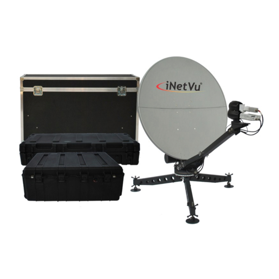
Internet at broadband speeds. The 1.2M Fly-1201 System comes with a protective case that has been designed to be airline checkable. Without the use of any tools, the Flyaway could be field assembled and operational in less than 10 minutes by one person. -
Page 6: Power Consumption
24 @ 3.5A = 84W Controller AC Universal Input: 90 ~ 264 VAC, 47 ~ 63 Hz ® The iNetVu Fly-1201 Flyaway system offers the following additional capabilities and features: 3-Axes DC motor drive system Highly reliable linear actuator to control elevation ... -
Page 7: Physical Outline
C-COM Satellite Systems Inc. Page 7 of 47 2. Physical Outline 2-piece Detachable reflector Polarization Assembly & Motor Feed Horn Can also go here Feed Arm Elevation Motor Azimuth Motor & Gear (3) Support Legs iNetVu ® Fly-1201 User Manual... -
Page 8: Clearance Requirements
C-COM Satellite Systems Inc. Page 8 of 47 3. Clearance Requirements Fig. 2: Clearance requirements for the iNetVu ® Fly-1201 Platform iNetVu ® Fly-1201 User Manual... -
Page 9: Assembly And Disassembly
2) Remove (3) legs from the case and install. One of the legs will have a label on it; this leg should be installed at the 130 degree marking on the AZ base. The AZ base will also have stickers indicating the install location of the back leg. iNetVu ® Fly-1201 User Manual... - Page 10 (back leg) should be pointing North (if located in Northern Hemisphere) and South (if location is in the Southern Hemisphere). Back Leg 4) Remove EL Feed Arm Support plate, fold arm brackets out as depicted in the image. iNetVu ® Fly-1201 User Manual...
- Page 11 6) Remove EL actuator assembly from the case; install bottom pin as shown making sure the actuator motor is on the right hand side with reference to the back of the EL support plate. Actuator Motor iNetVu ® Fly-1201 User Manual...
- Page 12 7) Supporting the actuator with your shoulder, connect the EL motor and EL tilt sensor cables by aligning the notches to the white dash. 8) Lower the EL Feed Arm Support plate onto the EL Actuator and tighten retaining nuts. iNetVu ® Fly-1201 User Manual...
- Page 13 11) The BUC can be installed at this stage if not already installed. Follow the “Installing BUC with the Universal Mounting Clamp kit” for mounting the BUC onto the mounting plate of the feed arm. iNetVu ® Fly-1201 User Manual...
- Page 14 12) Connect internal PL Motor, PL Tilt Sensor and RX/TX cables (coming from Feed arm) ensure to align groves marked by the white dash. 13) Open Reflector case and remove External Motor and Sensor cable. Motor/Sensor Cable iNetVu ® Fly-1201 User Manual...
- Page 15 15) Turn connector CW (clockwise) until it snaps into place, and a click is heard. Connect as well the RX and TX coax cables. Note TX is the top and RX the bottom connector as the label on the plate indicates. iNetVu ® Fly-1201 User Manual...
- Page 16 16) Connect cable labelled TX to BUC and RX to LNB. 17) Open Controller box (if applicable) back cover and connect external cables (Motor, Sensor and RX/TX cables). Also connect power, USB and LAN cable if required. 18) Power on iNetVu ® controller and launch iNetVu ®...
- Page 17 Bottom Section Section 21) Attach the bottom reflector section to the EL Support Plate assembly making sure the bottom (2) pins are in place first followed by the top (2), push and turn to lock. iNetVu ® Fly-1201 User Manual...
- Page 18 23) Lock the reflectors together using the three (3) latches on the back and on both sides of the reflector. 24) See section 4) for controller connectivity based on your desired connection preferences. ® 25) Congratulations, you have successfully assembled the iNetVu Flyaway System and are ready for Satellite search! iNetVu ®...
-
Page 19: Disassembly Procedure
Page 19 of 47 4.2. Disassembly Procedure 1) Click deploy Antenna icon on the iNetVu Controls screen. Antenna should deploy to EL=30, AZ=0 and PL=0. Reflector Assembly Removal 2) Unhook the three (3) latches holding the two-piece reflector together, and detach the top reflector assembly 3) Place top reflector in packaging case as shown in the image;... - Page 20 C-COM Satellite Systems Inc. Page 20 of 47 4) Detach the bottom section of the reflector, there are (4) locking retaining clamps to loosen. 5) Place bottom reflector section in the packaging case, close and lock the case. iNetVu ® Fly-1201 User Manual...
- Page 21 8) Disconnect the internal PL Tilt Sensor, PL Motor cable and LNB RX coax cable on the Feed Arm. 9) Loosen retaining nuts; detach the Feed Arm and POL Cage assembly from the EL Feed Arm Support plate. iNetVu ® Fly-1201 User Manual...
- Page 22 EL Feed Arm Support Plate and EL Actuator/Motor Assembly Removal 11) Loosen (2) retaining nuts on the EL Actuator, take extra care as the weight of the EL Support plate is also supported by these retaining screws. iNetVu ® Fly-1201 User Manual...
- Page 23 13) Disconnect all cables (Motor/Sensor, TX and RX). 14) Remove the Quick Release T-Pin attaching the elevation motor assembly to the AZ base; ensure to hold the actuator while removing the pin. iNetVu ® Fly-1201 User Manual...
- Page 24 C-COM Satellite Systems Inc. Page 24 of 47 15) Place the EL Actuator/Motor in the protective case. 16) Loosen (4) retaining nuts on the EL Support plate assembly. Remove EL Support Plate from the AZ base. iNetVu ® Fly-1201 User Manual...
- Page 25 AZ and Leg Assembly Removal 19) Loosen the retaining nuts on the (3) legs. Remove one leg at a time by tipping up the AZ assembly and pushing down on the leg. iNetVu ® Fly-1201 User Manual...
- Page 26 C-COM Satellite Systems Inc. Page 26 of 47 20) Place legs in the protective case; ensure the feet are folded with the flat surface facing down. 21) Place the AZ base in protective case. iNetVu ® Fly-1201 User Manual...
- Page 27 C-COM Satellite Systems Inc. Page 27 of 47 22) Coil up the Motor/Sensor external cable and place in reflector protective case or controller case. iNetVu ® Fly-1201 User Manual...
-
Page 28: Closing And Locking Cases
1) Close and lock latches shut on all (4) cases. 1. Reflector case 2. Feed Arm case 3. Controller case 4. AZ base and EL actuator case ® 2) Congratulations you have successfully packaged the iNetVu Fly-1201Flyaway System. iNetVu ® Fly-1201 User Manual... -
Page 29: System Connectivity
Page 29 of 47 5. System Connectivity The iNetVu ® Fly-1201 Flyaway Antenna has been built to operate with the iNetVu ® 7024 Series Controllers. The typical connection configuration for each service will be the same regardless of the Satellite Modem / VSAT. However, the configuration parameters for Satellite Modem / VSAT Communication will differ depending on service. -
Page 30: Network/Web Interface Connection
Cable RG6 Coaxial Cable Network Cable ® iNetVu Fly-1201 Platform Power Cable COMBINED MOTOR AND SENSOR CABLE Antenna 90 - 264VAC TX OUT Computer Satellite Modem / VSAT Fig. 4: iNetVu Typical Connection Configuration ® iNetVu ® Fly-1201 User Manual... -
Page 31: Typical Usb Communication Interface
RG6 Coaxial Cable Network Cable Power Cable ® iNetVu Fly-1201 Platform Antenna COMBINED MOTOR AND SENSOR CABLE USB Cable Network Cable 90 - 264VAC TX OUT Satellite Modem / VSAT Computer Fig. 5: USB Configuration Interface iNetVu ® Fly-1201 User Manual... -
Page 32: System Diagram With Splitter
Power Cable *The user may also setup the system with a splitter without a PC (must configure from LCD) or through USB interface instead of using Ethernet to interface between the PC and the 7024 Controller. iNetVu ® Fly-1201 User Manual... -
Page 33: Router Configuration Example
90 - 264VAC SUB: 255.255.255.0 GW: 192.168.1.1 RX IN LAN IP: 192.168.1.1 SUB: 255.255.255.0 WAN Port TX OUT Satellite Modem / VSAT Modem Example: Router 70.232.247.49 PC: DHCP Static: 192.168.1.2 SUB: 255.255.255.0 GW: 192.168.1.1 Computer iNetVu ® Fly-1201 User Manual... -
Page 34: Modem Independent Setup (Stand Alone)
Cable to interface between the 7024 Controller and the PC/Notebook. If the user does not wish to use a PC/Notebook, NO Cable is required and the user must configure the Controller from the LCD Interface. iNetVu ® Fly-1201 User Manual... -
Page 35: Using Modem Com Port
SAT IN SAT OUT PC/Notebook. shown in above wiring diagrams. If the user does Satellite Modem / VSAT wish PC/Notebook, NO Cable is required user must configure the 7000 Series Controller from the LCD Interface. iNetVu ® Fly-1201 User Manual... -
Page 36: Inetvu ® 7024 Controller Configuration
If you are located in the Southern Hemisphere (your GPS Latitude is South), the leg that is labeled should be pointed south 2) Power ON your PC/Notebook, 7024 Controller and install the iNetVu ® 7000 Mobile Software from the installation CD. - Page 37 255.255.255.X (Modem/Router Dependent) Gateway: A.B.C.D (Router/Modem IP) d. Click the “reset” button on the controller. 5) Run the iNetVu ® 7000 Mobile Software from the shortcut located on the desktop. Advance to the “Configuration” screen, by right clicking on the “Controls” screen, and selecting “Configuration”, and enter the controller IP address in the “IP...
- Page 38 Hemisphere of Operation (East or West) *Note: Freq (MHz), Symb (Ksps), IP, and Password fields are NOT required for Stand Alone Users (Type: NA), and may be left as is. Freq (MHz): (HNS Users Only) Enter the Modem Frequency iNetVu ® Fly-1201 User Manual...
- Page 39 11) Under the “Controller” section( on the Configuration screen), enter the following: Controller IP Address SUB: Controller Subnet Mask Controller Gateway DNS: Disregard PC IP: Same IP as Controller IP For iDirect/Viasat/Radyne/Comtech/Gilat/STM/Paradise Users using the Console Interface: ® iNetVu Fly-1201 User Manual...
- Page 40 *if you are using a splitter and powering the LNB from the modem, ensure the LNB Power is DIS. If you are powering the LNB from the controller, enter the proper LNB voltage requirements. 13) Congratulations you have successfully configured your iNetVu ® Flyaway System.
-
Page 41: Appendix
C-COM Satellite Systems Inc. Page 41 of 47 7. Appendix iNetVu ® Fly-1201 User Manual... -
Page 42: Azimuth & Elevation Manual Movements
7.1.1. Azimuth – Manually Moving the AZ Axis Step 1: Remove AZ motor cover. Step 2: Using a 7/16 wrench on the motor shaft move the AZ in the required direction. iNetVu ® Fly-1201 User Manual... -
Page 43: Elevation - Manually Moving The El Axis
Page 43 of 47 7.1.2. Elevation – Manually Moving the EL Axis Step 3: using the same size wrench on the EL motor shaft, move the EL in the desired direction. EL Motor Shaft AZ Motor Shaft iNetVu ® Fly-1201 User Manual... -
Page 44: Appendix 1: Transportable Cases Features And Specifications
Standard and cross-link polyethylene foams prevent component scuffing and absorb transit shock. screen-lined vents allow damp equipment to dry while preventing the likelihood of insect nesting within the case (this is what prevents the cases from being water/dust resistant) iNetVu ® Fly-1201 User Manual... -
Page 45: Appendix 2: Default Limits And Configuration Data Tables
PLATFORM TYPES 1200 Flyaway EL SLOW EL CURRENT6 3.5A EL CURRENT9 4.5A AZ SLOW AZ CURRENT6 1.7A AZ CURRENT9 2.0A PL SLOW PL CURRENT6 PL CURRENT9 Table 5 Default values for speed and current limits iNetVu ® Fly-1201 User Manual... -
Page 46: Appendix 3: Fly-1201 Abcd Dimensions
C-COM Satellite Systems Inc. Page 46 of 47 7.4. Appendix 3: Fly-1201 ABCD Dimensions 1.2m Reflector (Ku-Band) A – 54.37” B – 56.13” C – 40.45” D – 38.06” Reflector Feed Horn Fig. 6: ABCD Geometry Dimensions Note: The ABCD dimensions are preset by the manufacturer and should not be adjusted without C-COM’s guidance. -
Page 47: Appendix 4: Declaration Of Conformity
I, the undersigned, hereby declare that the equipment specified above conforms to the above Directives and Standards. Signed on behalf of the Manufacturer and Importer Place Ottawa, Canada Signature Date April 4, 2005 Full Name: Dr.Leslie Klein, P.Eng. Position: President and CEO iNetVu ® Fly-1201 User Manual...
Need help?
Do you have a question about the Fly-1201 and is the answer not in the manual?
Questions and answers