Table of Contents
Advertisement
Quick Links
- 1 Section 1 • General Information
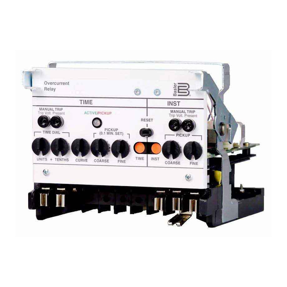
- 2 Figure 1-1. Be1-50/51B, S1 Case
- 3 Table 1-2. Be1-50/51B Overcurrent Relays, Five Ampere Ct Secondary, 50/60 Hz
- 4 Time Overcurrent (51) Element
- 5 Table 1-3. Time Characteristic Curve Constants with Sw3-3 Open (Off) (Series 100 Relays or Series 200 Relays)
- Download this manual
Advertisement
Chapters
Table of Contents


Need help?
Do you have a question about the BE1-50/51B-101 and is the answer not in the manual?
Questions and answers