Advertisement
Quick Links
Operating Manual
I. General Introduction
This brand new UT890C+/D Operating Manual is a handheld
3-5/6 digit True RMS Digital Multi-meter featuring stable performance
and high reliability. Its whole circuit design utilizes a large scale
integrated circuit that uses ∑△ADC converter as its core and is
further equipped with full function overload protection, making it an
ideal tool for users to measure the followings: DC and AC voltage,
electric current, resistance, capacitance, frequency, temperature
(UT890D/C+), diode, triode and continuity test.
Safety Rules and Instructions
● This unit is designed and produced in strict accordance with
GB4793, Safety Requirements for Electronic Measuring Instrument
and Safety Standards coded as IEC61010-1 and IEC1010-2-032. It
complies with safe standards, such as double insulation, over voltage
(CAT II 1000V, CAT III 600V) and class of pollution II. Please follow
the instructions contained in this manual, otherwise the protection
provided by this unit may be impaired.
● You should not use this unit unless its back cover is properly
secured in place, otherwise you are exposed to shock hazard.
● The range switch should be switched to a correct range.
● Check the insulation layer of the test leads to ensure no
damaged or broken cable.
● The red and black test leads should be well inserted into the
jacks that are in compliance with the measurement requirements to
ensure good contact.
● The input signal should not exceed the specified limit value
to avoid shock or unit damage.
● It is prohibited to change range when measuring voltage or
electric current so as to avoid unit damage.
● Damaged fuse must only be replaced with fuse with identical
specification.
● To avoid electric shock, the potential difference measured
between "COM" and earth "
" should be no more than 1000V.
● To avoid electric shock, test with great caution in case the
voltage to be measured maybe higher than DV 60V or AC 30Vrms.
● Battery should be replaced in time so as to ensure measurement
accuracy when the LCD displays "
".
● Power should be turned off immediately upon the test is completed
and battery should be taken out if it may not be used for a long
period of time.
● Do not use the unit under an environment with high temperature
and high humidity, especially not store it in a wet place as the
dampened unit may perform badly.
● Please do not change the circuit of the unit arbitrarily so as to
avoid unit damage or safety hazard.
● Maintenance: Please use wet cloth and mild detergent rather
than abrasive material or solvent for the cleaning of its exterior housing.
II. Symbol Description
Low battery
DC
Double Insulation
Auto shut off
Grounding
Relative Measurement
Diode
Buzzer
Fuse
AC
Warning
III. Characteristics
● More than 30 functional ranges are available.
● LCD display, visible area 63×29mm.
● Over range display "OL".
● Maximum displayed value 5999.
● Overload protection for all ranges.
● Auto power off.
● Temperature scope:
Working temperature: 0℃~40℃(32℉~104℉)
Storage temperature: -10℃~50℃(14℉~122℉)
● Low battery indicator: The symbol "
" will be displayed at top
left of the LCD.
● It has functions, including data hold, measurement of maximum/
minimum value, relative measurement, backlight, etc.
IV. Technical Indexes
Accuracy: ±(α% reading plus figure), 1 year warranty period
Environment Temperature: 23℃±5℃
Relative humidity: <75%
1. DC Voltage
Range
Resolution
Accuracy
600mV
0.1mV
±(0.5%+4)
6V
0.001V
±(0.5%+2)
60V
0.01V
600V
0.1V
1000V
1V
±(0.7%+10)
Input impedance: 1GΩfor the range of 600mV while 10MΩ for all
other ranges.
Overload protection: 750Vrms or at a peak value of 1000Vp-p.
2. AC Voltage
Range
Resolution
Accuracy
0.001V
6V
±(0.8%+3)
60V
0.01V
600V
0.1V
750V
1V
±(1.0%+10)
Input impedance: 10MΩfor all the ranges.
Frequency scope: 40Hz – 1KHz (Only applicable to sine wave and
triangular wave, but only being referable for other waves whose
frequencies are equal or higher than 200Hz.)
Guaranteed Accuracy: within 5~100% of its range and allow less t
han 5 figures of remaining reading in case of short circuit.
Overload Protection: 750Vrms or at a peak value of 1000Vp-p.
Display: True RMS
3. DC Current
Range
Resolution
Accuracy
0.01μA
60μA
±(0.8%+8)
6mA
0.001mA
60mA
0.01mA
0.1mA
600mA
±(1.2%+5)
20A
0.01A
±(2.0%+5)
Overload prote.ction: Fuse F1-630mA/250V, F2-20A/250V
Maximum input current: 20A (measuring electric current between
5A and 20A, testing time ≤10 seconds, Interval≥15 mins).
Measuring voltage drop: 600mV when at its full range.
4. AC Current
Range
Resolution
Accuracy
6mA
0.001mA
±(1.0%+12)
60mA
0.01mA
±(2.0%+3)
600mA
0.1mA
0.01A
±(3.0%+5)
20A
Overload protection: Fuse F1-630mA/250V, F2-20A/250V
Frequency scope: 40Hz – 1KHz (Only applicable to sine wave and
triangular wave, but only being referable for other waves whose
frequencies are equal or higher than 200Hz.)
Guaranteed Accuracy: within 5~100% of its range and allow less
than 2 figures of remaining reading in case of short circuit.
Maximum input current: 20A (measuring electric current between
5A and 20A, testing time ≤10 seconds, Interval≥15 mins) Measuring
voltage drop: 600mV when at its full range
Display: True RMS
5. Resistance
Range
Resolution
Accuracy
600Ω
0.1Ω
±(0.8%+5)
6kΩ
0.001kΩ
60kΩ
0.01kΩ
±(0.8%+3)
600kΩ
0.1kΩ
6MΩ
0.001MΩ
60MΩ
0.01MΩ
±(1.0%+25)
Range of 600Ω: measured value=displayed value - value shown when
test leads are short connected Open circuit voltage: About 1V
Overload protection: 600Vrms.
6. Capacitance
Range
Resolution
Accuracy
±(5.0%+35)
9.999nF
0.001nF
99.99nF~ 999.9μF
0.01nF~ 0.1μF
±(2.5%+20)
9.999mF
1μF
±(5.0%+10)
10mF≤C≤20mF:±(10.0%+5)
10μF
99.99mF
>20mF:reading is for reference only
Range: Auto (Reading for distributed capacitance of test leads may
be shown when the unit is in open circuit. It is recommended to use
REL mode to measure for any capacitance of less than 1μF)
Overload protection: 600Vrms.
7. Frequency
Range
Resolution
Accuracy
~0.01MHz
±(0.1%+5)
9.999Hz
~10.00MHz
0.001Hz
Range: Auto
Input frequency:
≤100KHz: 100mVrms≤Input frequency≤30Vrms;
>100kHz~1MHz: 200mVrms≤Input frequency≤30Vrms;
>1MHz: 600mVrms≤Input frequency≤30Vrms;
Overload protection: 600Vrms .
8.Diode & Buzzer Continuity Test
Range Description
Display forward voltage of the diode under test (approximate
value) and the range scope is 0~3V.
If it is equal or less than 10Ω, the buzzer beeps, indicating
circuit is closed; if it is equal or more than 100Ω,the buzzer
remain silence, indicating open circuit with a voltage of
approximately 1V.
Overload protection: 600Vrms .
9. hFE Test for Transistors
Range
Description
Test Condition
Base current is about
It can be used to test hFE specificiations
10μA, Vce is about
for Transistors of NPN or PNP type.
hFE
1.2V
Display range: 0-1000β
10. Temperature Test (Only for UT890C+)
Function
Range
Resolution
Accuracy
-40
~
0℃
±3
~
Temperature ℃
>0
100℃
1℃
±(1.0%+3)
>100~1000℃
±(2.0%+3)
-40~32
O
F
±5
Temperature ℃
±(1.5%+5)
>32~212
O
F
1
O
F
>212~1832
O
F
±(2.5%+5)
V. How to Use it:
Instructions before operating
(1). Once the unit is powered up, please check the 9V battery
contained in this unit, and if the battery
2
voltage is insufficient, there will be a
symbol "
" being displayed on the
3
1
screen, then the battery should be
4
replaced to ensure measurement
accuracy.
(2). The symbol "
" located beside
5
the jacks for test leads warns that for
the prevention of internal circuit from
being damaged, the input voltage or
6
current should not exceed the rated
(see Fig. 1)
value.
(3). Before measuring, the range switch should be switched into the
range needed.
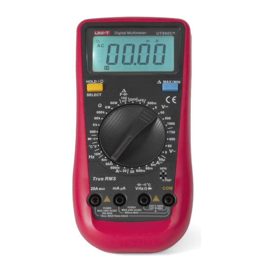
(4). Instrument Introduction (see Fig. 1):
① Combination keys: HOLD/
/SELECT(UT890C+)
② LCD
③ Combination keys: MAX MIN/
④ Range switch
⑤ Jack for transistor testing
⑥ Input Jack
1. DC Voltage Measurement
(1). Insert the black test lead into "COM", while insert the red test
lead into "V".
(2). Switch the range switch into the range "
". Then connect
the test leads in parallel with the power or load under test, the polarity
shown by the unit is the polarity of the terminal connected by the
red test lead.
Notes
1) If the voltage being measured remains unknown, turn the range
switch into the maximum range first and then gradually adjusting it
downward.
2) If "OL" is shown on the LCD, it indicates that it has exceeded the
range, so the range should be switched into a higher one.
3) The symbol "
" besides the "V" jack indicates that no voltage
higher than 1000V should be input into the unit, as though it is
possible to display a higher voltage, but this may incur a risk of
damaging internal wiring!
4) In case the input impedance is around 10MΩ, it may result in
measurement error if such load is connected into a circuit with high
impedance. Under most circumstances, if the circuit impedance is
less than 10kΩ, then the error is ignored (0.1% or even lower).
5) Especially be cautious to avoid shock when measuring high voltage.
2. AC Voltage Measurement
(1) Insert the black test lead into "COM", while insert the red test
lead into "V".
Advertisement

Related Manuals for UNI-T UT890D


Summary of Contents for UNI-T UT890D
- Page 1 Maximum input current: 20A (measuring electric current between (1). Insert the black test lead into “COM”, while insert the red test ● More than 30 functional ranges are available. (UT890D/C+), diode, triode and continuity test. Range Description lead into “V”.
- Page 2 REV.1 DATE:2015/07/07 any resistance higher than 1MΩ or even higher, it may take a few Notes again displays MAX value, repeating in this pattern. Press this key (2) Switch the range switch into the range “ ”. Then connect the 6.
Need help?
Do you have a question about the UT890D and is the answer not in the manual?
Questions and answers