Advertisement
Table of Contents
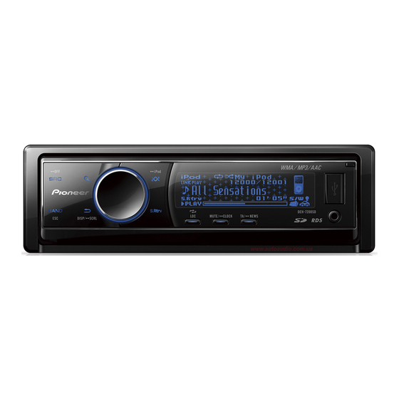
CD RDS RECEIVER
AUTORADIO CD RDS
SINTOLETTORE CD RDS
REPRODUCTOR DE CD CON RECEPTOR RDS
CD RDS-EMPFÄNGER
CD RDS-ONTVANGER
CD RDS ПРИЕМНИК
DEH-7200SD
Installation Manual
Manuel d'installation
Manuale d'installazione
Manual de instalación
Installationsanleitung
Installatiehandleiding
Руководство по установке
Printed in Thailand
Imprimé en Thaïlande
QRD3049-A/N
<
> EW
<KSNZX> <09J00000>
Installation
English
2. Secure the mounting sleeve by using
Note
a screwdriver to bend the metal tabs
• Check all connections and systems before final
(90°) into place.
installation.
Dashboard
• Do not use unauthorized parts. The use of
unauthorized parts may cause malfunctions.
• Consult with your dealer if installation requires
drilling of holes or other modifications of the
vehicle.
• Do not install this unit where:
— it may interfere with operation of the vehicle.
— it may cause injury to a passenger as a result
of a sudden stop.
• The semiconductor laser will be damaged if it
overheats. Install this unit away from hot places
such as near the heater outlet.
Mounting sleeve
• Optimum performance is obtained when the unit is
installed at an angle of less than 60°.
3. Install the unit as illustrated.
Nut
60°
Firewall or
metal support
Metal strap
Screw
DIN front/rear-mount
This unit can be properly installed either from
"Front" (conventional DIN Front-mount) or
Screw (M4×8)
"Rear" (DIN Rear-mount installation, utilizing
threaded screw holes at the sides of unit
chassis). For details, refer to the following
installation methods.
• Use commercially available parts when
installing.
• Make sure that the unit is installed securely
in place. An unstable installation may cause
DIN Front-mount
skipping or other malfunctions.
1. Insert the mounting sleeve into the
DIN Rear-mount
dashboard.
1. Determine the appropriate position
For installation in shallow spaces, use the
where the holes on the bracket and
supplied mounting sleeve. If there is enough
space, use the mounting sleeve that came with
the side of the unit match.
the vehicle.
Installation
English
2. Tighten two screws on each side.
Tapping screw (5 mm × 8 mm)
Mounting bracket
Dashboard or Console
Removing the unit
1. Extend top and bottom of the trim
ring outwards to remove the trim
ring. (When reattaching the trim ring,
point the side with the groove down.)
Trim ring
• Releasing the front panel allows easier access
to the trim ring.
2. Insert the supplied extraction keys
into both sides of the unit until they
click into place.
3. Pull the unit out of the dashboard.
Advertisement
Table of Contents

Related Manuals for Pioneer DEH-7200SD


Summary of Contents for Pioneer DEH-7200SD
- Page 1 • The semiconductor laser will be damaged if it CD RDS ПРИЕМНИК 1. Extend top and bottom of the trim overheats. Install this unit away from hot places DEH-7200SD ring outwards to remove the trim such as near the heater outlet. Mounting sleeve ring. (When reattaching the trim ring, • Optimum performance is obtained when the unit is installed at an angle of less than 60°.
-
Page 2: Installation
Installation Français Installation Français Installazione Italiano Installazione Italiano 2. Fixez le manchon de montage en 2. Serrez deux vis de chaque côté. 2. Assicurare il supporto di montaggio 2. Serrare con due viti su ciascun lato. Remarque Nota utilisant un tournevis pour courber utilizzando un cacciavite per piegare Vis taraudeuse (5 mm × 8 mm) Vite autofilettante (5 mm × 8 mm) • Vérifiez toutes les connexions et tous les les pattes métalliques (90°) en place. • Prima dell’installazione finale vi raccomandiamo le linguette metalliche (90°) in systèmes avant l’installation finale. -
Page 3: Instalación
Instalación Español Instalación Español Einbau Deutsch Einbau Deutsch 2. Fije el manguito de montaje 2. Apriete los dos tornillos en cada lado. 2. Befestigen Sie den Montagerahmen 2. Ziehen Sie auf jeder Seite zwei Nota Hinweise utilizando un destornillador para mithilfe eines Schraubendrehers: Die Schrauben fest. Tornillo con rosca cortante (5 mm × 8 mm) doblar las pestañas metálicas (90°) y • Überprüfen Sie alle Anschlüsse und Systeme, Metallklammern sind in eine sichere • Verifique todas las conexiones y sistemas antes de Blechschraube (5 mm ×... - Page 4 Установка Pycckий Установка Pycckий Installatie Nederlands Installatie Nederlands 2. Закрепите монтажную обойму, 2. Затяните по два винта с каждой 2. Zet de montagebehuizing vast door 2. Draai aan elke kant twee schroeven Opmerking Примечание подогнув с помощью отвертки стороны. met een schroevendraaier de metalen vast. • Проверьте все соединения и системы перед металлические язычки (90°) на • Controleer alle aansluitingen en systemen voor de lipjes op hun plaats te buigen (90°).
-
Page 5: Connecting The Units
Connecting the units English Connecting the units English Connection Diagram • Control signal is output through blue/white cable 18. Yellow/black Note when this unit is powered on. Connect it to an If you use an equipment with Mute function, 1. This product external power amp’s system remote control or 23. To rear output • When this unit is installed in a vehicle without wire this lead to the Audio Mute lead on that 2. Rear output the vehicle’s auto-antenna relay control terminal ACC (accessory) position on the ignition switch, 26. - Page 6 Connexions des appareils Français Connexions des appareils Français Collegamento delle unità Italiano Collegamento delle unità Italiano Diagramme de connexion Schema di collegamento • Le signal de commande est sorti par le câble 19. Bleu/blanc • Quando l’unità è accesa il segnale di controllo 20. Blu/bianco (6*) Remarque Nota bleu/blanc quand cet appareil est sous Connectez à la prise de commande du système è posto in uscita attraverso il cavo blu/bianco. Da collegare al terminale di controllo del relé 1. Cet appareil 1.
- Page 7 Conexión de las unidades Español Conexión de las unidades Español Anschließen der Geräte Deutsch Anschließen der Geräte Deutsch Diagrama de conexión Anschlussdiagramm • La señal de control se emite a través del cable 19. Azul/blanco • Das Steuersignal wird über das blaue/ 18. Gelb/schwarz Nota Hinweise azul/blanco cuando se enciende esta unidad. Conecte al terminal de control de sistema del weiße Kabel ausgegeben, wenn dieses Falls Sie ein Gerät mit Stummschaltfunktion 1. Este producto 1. Dieses Produkt Conéctelo a un terminal de control de sistema de Gerät eingeschaltet wird. Schließen Sie amplificador de potencia (máx.
- Page 8 Подключение устройств Pycckий Подключение устройств Pycckий Aansluiten van de toestellen Nederlands Aansluiten van de toestellen Nederlands Схема Соединений 18. Желтый/черный Aansluitingsschema • Контрольный сигнал выходит по сине/белому • Via de blauw/witte draad wordt een stuursignaal 18. Geel/zwart Примечание Opmerking кабелю, когда данное устройство подключено Если вы пользуетесь устройством, на geproduceerd wanneer dit toestel is ingeschakeld. Als u apparatuur met een zg. Mute functie 1.
Need help?
Do you have a question about the DEH-7200SD and is the answer not in the manual?
Questions and answers