
Related Manuals for Launch X-631


Summary of Contents for Launch X-631
- Page 1 Launch X-631 Wheel Aligner Maintenance Manual Table of Content X-631 Wheel Aligner Maintenance Manual...
-
Page 2: Table Of Contents
Launch X-631 Wheel Aligner Maintenance Manual Table of Content Table of Content Preface ......................................0-1 Target Reader ..................................0-1 Purpose ....................................0-1 Required Knowledge ................................0-1 Summary Table of Maintenance and Testing Items ......................1-1 Maintenance and Testing for Cabinet Assembly ........................2-1 Item1: Visual Inspection for Cabinet .........................2-1 Item2: Cabinet Wiring Inspection ..........................2-2... -
Page 3: Preface
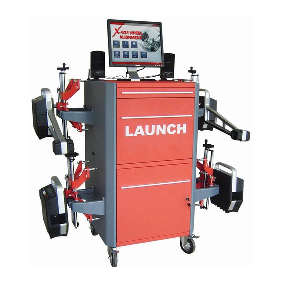
The main content of this manual is to introduce the wheel aligner of model X-631. In this manual, author describes the wheel aligner by using a lot of practical pictures and explication to avoid unnecessary misunderstanding caused by over-many special items. -
Page 4: Summary Table Of Maintenance And Testing Items
Launch X-631 Wheel Aligner Maintenance Manual Summary Table of Maintenance and Testing Items Summary Table of Maintenance and Testing Items Client Manufacturer Launch Service No. Main unit serial No. Maintenance and testing for cabinet assembly Visual inspection for cabinet Cabinet wiring inspection... -
Page 5: Maintenance And Testing For Cabinet Assembly
Launch X-631 Wheel Aligner Maintenance Manual Testing for Cabinet Assembly Maintenance and Testing for Cabinet Assembly Item1: Visual Inspection for Cabinet Check cabinet portiere and door for damage and well movement, and check its surface for serious scratch, etc. ... -
Page 6: Item2: Cabinet Wiring Inspection
Launch X-631 Wheel Aligner Maintenance Manual Testing for Cabinet Assembly Item2: Cabinet Wiring Inspection Check if the wiring inside the cabinet is abnormal: Check if it is removed by others; Check if the connection screw is loose; Check if the cable cover is damaged. -
Page 7: Item3: Power Cable Inspection
Launch X-631 Wheel Aligner Maintenance Manual Testing for Cabinet Assembly Item3: Power Cable Inspection Check power supply cable for damage and plug for distortion Item4: Power Supply Switch Inspection Power strip down-lead Power supply in-lead Front side Connection on back side Note: 1. -
Page 8: Item5: Charging Socket Inspection
Launch X-631 Wheel Aligner Maintenance Manual Testing for Cabinet Assembly Item5: Charging Socket Inspection Front side — Check if 6pin flange plug plugs and pulls flexibly Back side — Check if the cable is broken 6pin flange socket female Red for Positive and Black for Negative;... -
Page 9: Item6: Switch Power Supply Inspection
Launch X-631 Wheel Aligner Maintenance Manual Testing for Cabinet Assembly Item6: Switch Power Supply Inspection Output voltage adjusting potentiometer Note: 1. Check if the power supply switch is loose; 2. Test with multi-meter if the output voltage of the switch power supply is 9.3±0.1V. If the deviation of output... -
Page 10: Item7: Power Strip Inspection
Launch X-631 Wheel Aligner Maintenance Manual Testing for Cabinet Assembly Item7: Power Strip Inspection Note: 1. Check if the power strip is loose and each switch switches well; 2. Test with multi-meter if the output voltage of the power strip is normal (AC220V±10%). -
Page 11: Item8: Computer Inspection And Cleaning
Launch X-631 Wheel Aligner Maintenance Manual Testing for Cabinet Assembly Item8: Computer Inspection and Cleaning Note: 1. Open the chassis, clear away the dust inside the switch power supply and on the main-board with wind gun; 2. Check if each connector and memory bank is loose. -
Page 12: Item9: Mouse And Keyboard Inspection And Cleaning
Launch X-631 Wheel Aligner Maintenance Manual Testing for Cabinet Assembly Serial port 2 Parallel socket Voltage switching shift (110V/220V) Serial port 1 Power socket Mouse socket Sound box socket Keyboard socket USB Socket NIC Socket Monitor data socket Note: 1. Pull each connector, check carefully if the pins are in good condition;... -
Page 13: Item10: Computer System Inspection And Disk Maintenance
Launch X-631 Wheel Aligner Maintenance Manual Testing for Cabinet Assembly Item10: Computer System Inspection and Disk Maintenance Check if the hardware configuration is normal (if it is not normal, the yellow exclamatory mark will be displayed ) Check if the files in... -
Page 14: Item11: Rf Emitter/Receiver Box Inspection
Launch X-631 Wheel Aligner Maintenance Manual Testing for Cabinet Assembly Item11: RF Emitter/Receiver Box Inspection Emitter indicator Antenna down-lead Receiver indicator Power supply indicator Cover-opened picture Note: 1. Check RF box and connecting cable for damage; 2. Open the cover, and then check the antenna base and connection base for oxidation and rust;... -
Page 15: Item12: Antenna And Rf Cable Inspection
Launch X-631 Wheel Aligner Maintenance Manual Testing for Cabinet Assembly Item12: Antenna and RF Cable Inspection Note: Check if RF cable and cupula antenna are damaged, and check if the connectors and antenna plastic bush are fastened firmly. Item13: Printer Inspection... -
Page 16: Maintenance And Testing For Measurement Probe Rod
Launch X-631 Wheel Aligner Maintenance Manual Maintenance and Testing for Measurement Probe Rod Maintenance and Testing for Measurement Probe Rod Item14: Visual Inspection and Cleaning for Probe Rod 1. Clear away the oil dirt on the film; 2. Clear away the oil dirt on each surface and inside the gaps. -
Page 17: Item15: Level Bubble Inspection
Launch X-631 Wheel Aligner Maintenance Manual Maintenance and Testing for Measurement Probe Rod Clear away the oil dirt and dust inside the wheel clamp axle and cable trough Item15: Level Bubble Inspection Level bubble Note: 1. Check if the liquid inside the level bubble is normal, and if the glass body is broken;... -
Page 18: Item16: Lcd Display Screen Inspection
Launch X-631 Wheel Aligner Maintenance Manual Maintenance and Testing for Measurement Probe Rod Item16: LCD Display Screen Inspection Note: 1. In case of switching off, check if there are black dots on LCD screen, and check if the LCD screen is broken;... -
Page 19: Item18: Wheel Clamp Axle Inspection
Launch X-631 Wheel Aligner Maintenance Manual Maintenance and Testing for Measurement Probe Rod Current shift Note: According to the above figure, plug two black leads of the battery together, connect two probes of multi-meter (at AC/DC shift) to the other two red leads respectively (to form a complete serial circuit), and then plug the charging cable of the probe rod. -
Page 20: Item19: Acrylic Panel And Key-Press Inspection
Launch X-631 Wheel Aligner Maintenance Manual Maintenance and Testing for Measurement Probe Rod Item19: Acrylic Panel and key-press Inspection Power supply Backlight lamp Previous Next Run-out compensation N/A Note: 1. Check the surface of Acrylic panel and key-press, and then test each key-press for good hand feel;... -
Page 21: Item21: Testing For Wireless Communication Function
Launch X-631 Wheel Aligner Maintenance Manual Maintenance and Testing for Measurement Probe Rod Item21: Testing for Wireless Communication Function Probe rod communication Probe rod electricity status quantity status Note: Switch on the computer host, the Status of Probe Rod interface will be displayed as shown in the above figure;... -
Page 22: Maintenance And Testing For Some Components
Launch X-631 Wheel Aligner Maintenance Manual Maintenance and Testing for Some Components Maintenance and Testing for Some Components Item22: Mechanical Turntable Inspection Locking pin Locknut Front side Back side Note: 1. Check the turntable surface for paint removing and rusting condition;... -
Page 23: Item23: Wheel Clamp Inspection
Launch X-631 Wheel Aligner Maintenance Manual Maintenance and Testing for Some Components Item23: Wheel Clamp Inspection Wheel clamp hole base Locking handle Rotary handle Clamping claw Note: 1. Check the wheel clamp for distortion (especially for clamping claw); 2. Check if the rotary handle can rotate normally or not, and check if the clamping claw can flex freely. -
Page 24: Item24: Brake Pedal Depressor Inspection
Launch X-631 Wheel Aligner Maintenance Manual Maintenance and Testing for Some Components Item24: Brake Pedal Depressor Inspection Clip plate Moving assembly Note: 1. Check the brake pedal depressor for distortion and damage; 2. Check if clip plate spring can move normally, and check if the moving assembly can slide along the leader freely. -
Page 25: Probe Rod Calibration
X-631 Wheel Aligner Maintenance Manual Probe Rod Calibration Probe Rod Calibration The probe rod calibration procedures are as follows: After starting the computer, the system will enter the Probe Rod Maintenance interface of X-631 test program. Structure of calibrating frame ... - Page 26 Launch X-631 Wheel Aligner Maintenance Manual Probe Rod Calibration Install the small calibration frame well according the installation requirements, and then adjust the lateral axle and vertical axle level (It is required to use the probe rods for auxiliary level adjustment of the small calibration frame).
- Page 27 Launch X-631 Wheel Aligner Maintenance Manual Probe Rod Calibration Converter connector Converter connector ● Check if the linearity of the lateral axle is up to standard: Install 1# and 2# probe rod on the two ends of the lateral axle respectively (as shown in the following figure), read the corresponding CCD values from computer test program, and then compare the values with the corresponding calibrated values in CHECK file, the difference between them are required to be less than 2 percent;...
- Page 28 Launch X-631 Wheel Aligner Maintenance Manual Probe Rod Calibration Lateral axle level bubble Vertical axle level bubble 横轴水平泡 纵轴水平泡 Calibration for 1# and 2# clinometer and end CCD camera Computer interface First, please remove the two vertical axles from the small calibration frame, and then install 1# and 2# probe rods at...
- Page 29 Launch X-631 Wheel Aligner Maintenance Manual Probe Rod Calibration previous step) Computer interface Last step: click [NEXT] to save data as shown in the following figure (new “check.ini” file will be saved under the installation directory).
- Page 30 Launch X-631 Wheel Aligner Maintenance Manual Probe Rod Calibration Computer interface...
Need help?
Do you have a question about the X-631 and is the answer not in the manual?
Questions and answers
Necesito comprar estos dispositivos me podrían ayudar gracias
You can purchase the Launch X-631 device from the website launchx431.net. Add the product to your cart and proceed through the checkout process, where you can select your preferred shipping method. Once you place an order, you will receive a confirmation email and later a tracking number when the order is shipped.
This answer is automatically generated