Table of Contents
Advertisement
TopPage
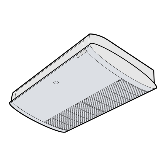
CEILING TYPE
FLOOR TYPE
[1]
SPECIFICATION.................................... . ....... 1-1
[2]
EXTERNAL DIMENSION....................... . ....... 1-2
[3]
WIRING DIAGRM .................................. . ....... 1-4
[4]
ELECTRICAL PARTS ............................ . ....... 1-4
[1]
BLOCK DIAGRAMS............................... . ....... 2-1
[2]
[3]
FUNCTION............................................. . ....... 2-7
[1]
TROUBLESHOOTING GUIDE............... . ....... 3-1
[2]
ACTERISTICS ....................................... . ....... 3-5
[3]
UNIT INDEPENDENTLY........................ . ....... 3-5
Parts marked with "
" are important for maintaining the safety of the set. Be sure to replace these parts with specified ones for maintaining the
safety and performance of the set.
SERVICE MANUAL
ROOM AIR CONDITIONERS
MODELS
INDOOR UNIT
GS-XP12HR-N
In the interests of user-safety (Required by safety regulations in some
countries) the set should be restored to its original condition and only
parts identical to those specified should be used.
CONTENTS
........ 2-3
No. XXXXXXXXXXXXX
SPLIT TYPE
[1]
FLOW FOR REFRIGERANT .........................4-1
[2]
STANDARD CONDITION ..............................4-1
[3]
PRESSURE IN 3-WAY VALVE ......................4-1
[4]
PERFORMANCE CURVES...........................4-1
[1]
DISASSEMBLY OF INDOOR UNIT...............5-1
[2]
DISASSEMBLY OF OUTDOOR UNIT.........5-13
Parts Guide
This document has been published to be used for
after sales service only.
The contents are subject to change without notice.
xxxxxxxxx
OUTDOOR UNIT
AE-X12FR-N
Advertisement
Table of Contents

Related Manuals for IVT GS-XP12HR-N


Summary of Contents for IVT GS-XP12HR-N
-
Page 1: Table Of Contents
SPLIT TYPE ROOM AIR CONDITIONERS MODELS INDOOR UNIT OUTDOOR UNIT GS-XP12HR-N AE-X12FR-N CEILING TYPE In the interests of user-safety (Required by safety regulations in some countries) the set should be restored to its original condition and only parts identical to those specified should be used. -
Page 2: Chapter 1. Specification
GSXP12HRN CHAPTER 1. GSXP12HRN SPECIFICATION Service Manual [1] SPECIFICATION 1. GS-XP12HR-N / AE-X12FR-N MODEL INDOOR UNIT OUTDOOR UNIT ITEMS GS-XP12HR-N AE-X12FR-N Cooling capacity (Min. ~ Max.) 3.5 (0.9 - 4.0) Heating capacity (Min. ~ Max.) kW 4.2 (0.9 - 6.0) -
Page 3: External Dimension
GSXP12HRN [2] EXTERNAL DIMENSION 1. GS-XP12HR-N / AE-X12FR-N 1.1. Indoor unit 18.5 INVERTER AIR CONDITIONER CRMC-A442JBE0 R03(AAA) 2PCS. SHARP CORPORATION 22.0 1025 1.2. Outdoor unit 37.5 167.5 1 – 2... - Page 4 GSXP12HRN 1.3. Installation demensions 1.3.1 Ceiling type Horizontal base line Hole for drainage pipe (Ø 50mm) (VIEW FROM FRONT) Hole for refrigerant (unit size) and drainage pipe 1025 (Ø 80mm) (bolt pich) Hole for refrigerant (VIEW FROM CEILING) and drainage pipe (Ø...
-
Page 5: Wiring Diagrm
GSXP12HRN [3] WIRING DIAGRM 1. Indoor unit 1.1. GS-XP12HR-N 2. Outdoor unit 2.1. AE-X12FR-N [4] ELECTRICAL PARTS 1. Indoor unit 1.1. GS-XP12HR-N DESCRIPTION MODEL REMARKS Indoor fan motor MLB052 220 - 240V, 50Hz Indoor fan motor capacitor – 450V, 3µF Transformer –... - Page 6 GSXP12HRN DESCRIPTION MODEL REMARKS Outdoor fan motor ML-A902 DC Motor – QFS-GA064JBZZ (250V, 1A) – QFS-GA051JBE0 (250V, 2A) – QFS-GA052JBZZ (250V, 3.15A) – QFS-CA001JBZZ (250V, 20A) Fu5, 6 – QFS-CA002JBZZ (250V, 15A) 1 – 5...
-
Page 7: Chapter 2. Explanation Of Circuit And Op- Eration Block Diagrams
GSXP12HRN CHAPTER 2. GSXP12HRN EXPLANATION OF CIRCUIT AND OPERATION Service Manual [1] BLOCK DIAGRAMS 1. INDOOR UNIT DC power supply circuit AC power 3.15 A Fan motor phase control circuit Room fan motor FUSE1 Rotation pulse input circuit Fan motor pulse detect AC clock circuit Louvre motor drive circuit Flow direction control... - Page 8 GSXP12HRN 2. OUTDOOR UNIT AC clock circuit protection Pulse amplitube modulation circuit IGBT protection Unit-unit wiring (AC power Power supply circuit Smoothing Power factor Filter circuit converter circuit circuit and serial signals) CPU oscillator circuit 3.15A DC overvoltage detection circuit protection Outdoor fan Outdoor fan drive circuit...
-
Page 9: Microcomputer Control System
GSXP12HRN [2] MICROCOMPUTER CONTROL SYSTEM 1. INDOOR UNIT 1.1. Electronic Control Circuit Diagram 2 – 3... - Page 10 GSXP12HRN 1.2. Printed Wiring Board 2 – 4...
- Page 11 GSXP12HRN 2. OUTDOOR UNIT 2.1. Electronic Control Circuit Diagram 2 – 5...
- Page 12 GSXP12HRN 2.2. Printed Wiring Board 2 – 6...
-
Page 13: Function
GSXP12HRN [3] FUNCTION 1. INDOOR UNIT 1.1. Startup control Temperature of the indoor heat exchanger The main relay remains off during the first 45 seconds (first safety Preset Fan speed 35ºC time) immediately after the power cord is plugged into an AC outlet in 32ºC order to disable outdoor unit operation and protect outdoor unit electric The indoor fan operates at low speed. - Page 14 GSXP12HRN * During Cooling / Dry • Power ON/OFF • Automatic operation mode setting Timer set time • Swing louver Room temperature • Plasmacluster operation mode 1ºC Setting not memorized hour • Timer setting Timer operation starts Stops • Full power setting 1.8.
- Page 15 Heating operation ing frequency and operating status, the operating frequency is decreased by about 4 to 15 Hz. Then, this operation is repeated every GS-XP12HR-N Approx. 6.4 A Approx. 7.5 A 60 seconds until the temperature of the indoor unit heat exchanger 2.6.
- Page 16 GSXP12HRN 3. Explanation of cluster circuit The cluster unit generates cluster ions, which are circulated throughout the room by the air flow created by the blower fan (indoor unit fan motor) in the air conditioner unit. 1) When microcomputer output turns "H," the IC6 output changes to "Lo," turning ON the SSR and applying 230 V to the cluster unit for the genera- tion of cluster ions (positive and negative ions).
- Page 17 GSXP12HRN When the IGBT is ON, an electric current flows to the IGBT via the reactor (L5), (L6) and diode bridge (DB2). When the IGBT turns OFF, the energy stored while the IGBT was ON is charged to the voltage doubler capacitor via the diode bridge (DB1). As such, by varying the ON/OFF duty of the IGBT, the output voltage is varied.
-
Page 18: Explanation Of Ipm Drive Circuit
GSXP12HRN 4.3. PAM protection circuit To prevent excessive voltage of PAM output from (Overvoltage detection) damaging the IPM and electrolytic capacitor as well as the control printed circuit board (PCB), this circuit monitors the PAM output voltage and turns off the R112 R114 255K... - Page 19 GSXP12HRN 5.1. IPM drive power supply circuit The power supply for the upper-phase IGBT (HU, HV, HW) drive employs a bootstrap system, and provides power to the upper-phase IC. The 15-V power supply for the lower-phase IC is provided by the control printed circuit board (PCB). 5.1.1 Brief explanation of bootstrap system (single power drive system) To supply power to the upper-phase IC, the microcomputer (IC1) turns ON the lower-phase IGBT (LU, LV, LW).
- Page 20 GSXP12HRN 5.1.2 DC overcurrent detection circuit When a current of about 25 A or higher flows through the shunt resistance (R49) on the control printed circuit board (PCB), the voltage at this resis- tance is input to IPM CIN pin (26). Then, the gate voltage of the lower-phase IGBT (LU, LV, LW) inside the IPM turns OFF to cut off the overcurrent. At the same time, an L output of about 1.8 ms is generated from IPM Fo pin (24), and this results in an L input to overcurrent detection input pin (34) of the microcomputer (IC1) and turns OFF the PWM signal output (IC1 pins (51) through (56)) to the IGBT gate.
- Page 21 GSXP12HRN The microcomputer performs internal processing to cancel spike voltage during the regenerative process. Furthermore, even if the induced voltage is low, position detection is still possible, thus allowing sensor-less operation at low rotation speed in the ini- tial stage of operation. This reduces the starting current and improves the IPM reliability. Terminal voltage waveform Reference voltage (1/2 of DC voltage)
-
Page 22: Chapter 3. Troubleshooting
GSXP12HRN CHAPTER 3. GSXP12HRN TROUBLESHOOTING Service Manual [1] TROUBLESHOOTING GUIDE 1. SELF-DIAGNOSIS FUNCTION AND DISPLAY MODE 1) To call out the content of the self-diagnosis memory, hold down the emergency operation button for more than five seconds when the indoor unit is not operating. - Page 23 GSXP12HRN : Flashes in 2-sec intervals (normal), : On, : Off, : Flashes 3 times in 0.2-sec intervals (When LED1 on the outdoor unit flashes in 2-sec intervals, the outdoor unit is in normal condition.) Indication by operation lamp on indoor unit Indication by Status of Content of diagnosis...
- Page 24 GSXP12HRN : Flashes in 2-sec intervals (normal), : On, : Off, : Flashes 3 times in 0.2-sec intervals (When LED1 on the outdoor unit flashes in 2-sec intervals, the outdoor unit is in normal condition.) Indication by operation lamp on indoor unit Indication by Status of Content of diagnosis...
- Page 25 GSXP12HRN 2. CAUTION IN CHECKING PRINTED CIRCUIT BOARDS (PWB) [GS-XP12HR-N] 2.1. Non-insulated control circuit The GND terminals of the low-voltage circuits (control circuits for microcomputer and thermistors and drive circuits for expansion valve and relays) on the control printed circuit board (PWB) are connected to the compressor drive power supply (320-VDC negative terminal). Therefore, exercise utmost caution to prevent electric shock.
-
Page 26: Thermistor Temperature Characteristics
GSXP12HRN [2] THERMISTOR TEMPERATURE CHARACTERISTICS 0.1. Temperature properties of indoor thermistors TH1 Room temperature thermistor TH2 Heat exchange thermistor TH3 Valve temperature thermistor Connector Connector CN14 CN13 0ºC resistance Room temperature 14.5 K thermistor TH1 (yellow) 25ºC resistance 10 K 25ºC resistance 4.431 K Tester... -
Page 27: Chapter 4. Refrigeration Cycle
Temp. Humidity Cooling 27°C 35°C Heating 20°C – 7°C * REFRIGERANT PIPE LENGTH 5.0m [3] TEMPERATURE AT EACH PART AND PRESSURE IN 3-WAY VALVE Model GS-XP12HR-N Operation mode MAX. TEST RUN Cool Heat Cool Heat R.P.M. 5000 5600 2500 2500 73.6°C... - Page 28 GSXP12HRN 0.1. At Cooling 0.2. At Heating 1100 1000 1000 Outside air temp.(ºC) Outside air temp.(ºC) 4 – 2...
-
Page 29: Chapter 5. Disassembling Procedure
GSXP12HRN CHAPTER 5. GSXP12HRN DISASSEMBLING PROCEDURE Service Manual [1] DISASSEMBLY OF INDOOR UNIT CAUTION: DISCONNECT THE UNIT FROM POWER SUPPLY BEFORE ANY SERVICING. 1) Slide 2 Grille hooks to the left, and open the Grille. (Right and left 3) Remove the screw fixing the Side cover. (Right and left Side cover.) Grille.) Side Cover Side Cover... - Page 30 GSXP12HRN 5) Remove 1 screw fixing the Angle. 6) Cut the fixing band. Remove the Angle to the direction of arrows. Disconnect 2 connectors (CN202, CN203). Remove the screw fixing the Display unit. 5 – 2...
- Page 31 GSXP12HRN 7) Slide the Display unit to the direction of arrow. 10)Support the Front panel with your hand, and remove the screw. Slide 8) Remove 2 screws fixing the Angle to the Front panel. 11)Remove the Front panel to the position where the Front panel is separated from the Drain pan.
- Page 32 GSXP12HRN 12)Remove the Front panel to the direction of arrow. CAUTION: WHEN YOU ASSEMBLE THE FRONT PANEL TO CAUTION: DO NOT DAMAGE THE DRAIN PAN WITH THE DIS- DRAIN PAN, INSERT HOOK OF THE FRONT PANEL PLAY HOLDER. BETWEEN ANGLE AND DRAIN PAN (2 POSI- TIONS).
- Page 33 GSXP12HRN 14)Remove 9 screws fixing the Drain pan ass'y. 16)Tilt the Drain pan ass'y, slide the Drain pan ass'y to the direction of arrow. Right and left side. Right and left side. 15)Remove 3 insulators and 4 screws fixing the Drain pan ass'y. 17)Disconnect 4 connectors (CN206, CN207, CN208 and CN210).
- Page 34 GSXP12HRN 18)Disconnect the connector (CN302). Remove 2 screws fixing the Top duct cover L. 19)Remove 2 screws fixing the top duct. 21)Remove 2 screws fixing the Top duct cover R. Remove the Top duct cover R and H-louver ass'y. 20)Tilt the Top duct for removing the rib of the Top duct , remove the unit to the direction of arrow.
Need help?
Do you have a question about the GS-XP12HR-N and is the answer not in the manual?
Questions and answers