
Related Manuals for Spectracom GSG-5 Series


Summary of Contents for Spectracom GSG-5 Series
- Page 1 GSG-5/6 Series GNSS Simulator User Manual with SCPI Guide Spectracom Part No.: 4031-600-54001 Revision: 26 Date: 16-Jan-2018 spectracom.com...
- Page 3 Spectracom reserves the right to make changes to the product described in this document at any time and without notice. Any software that may be provided with the product described in this document is furnished under a license agreement or nondisclosure agreement.
- Page 4 Blank page. User Manual GSG-5/6 Series...
-
Page 5: Table Of Contents
CHAPTER 1 Introduction 1.1 Quick Start 1.2 Welcome 1.3 Key Features 1.4 Typical GSG Applications 1.5 Intended Use and Operating Principle 1.6 Compliance & Legal Notices 1.6.1 About this Document 1.6.2 Declaration of Conformity 1.7 Technical Specifications 1.7.1 RF Output Specifications 1.7.2 Rear Panel Outputs and Inputs 1.7.3 Time Base 1.7.4 Optional Antenna... - Page 6 2.5.2 Transmit Power Level CHAPTER 3 Features & Functions 3.1 Front Panel 3.1.1 Description of Keys 3.1.1.1 Power 3.1.1.2 Start 3.1.1.3 Exit 3.1.1.4 Cancel 3.1.1.5 Menu 3.1.1.6 View 3.1.1.7 Enter 3.1.1.8 Arrows 3.1.1.9 N/S 3.1.1.10 E/W 3.1.1.11 Numeric Keys 3.1.1.12 +/– (format) 3.1.1.13 [.] (hold) 3.2 Rear Panel 3.3 The GSG Main Menu...
- Page 7 3.5.5.3 User-Uploaded Ephemeris 3.5.6 Leap Second 3.5.7 Event Data 3.5.8 Antenna Settings 3.5.8.1 Antenna model 3.5.8.2 Lever arm 3.5.8.3 Elevation mask 3.5.9 Advanced Configuration Options 3.5.9.1 Multipath Signals 3.5.9.2 Interference signals 3.5.9.3 Base station 3.5.9.4 Environment models 3.5.9.5 Atmospheric model 3.5.10 Satellite Configuration 3.5.10.1 Satellite Systems 3.5.10.2 Number of Satellites...
- Page 8 3.6.6 Restore Factory Defaults 3.6.7 Calibration CHAPTER 4 Frequent Tasks 4.1 Working with Scenarios 4.1.1 Scenario Start/Stop/Hold/Arm 4.1.2 Running a Scenario 4.1.3 Holding a Scenario 4.1.4 Configuring a Scenario 4.2 Locking/Unlocking the Keyboard 4.3 Setting Transmit Power 4.4 Accessing the GSG Web Interface 4.5 Using the CLI 4.6 Performing a Receiver Cold Start 4.7 Creating a One-Line Trajectory...
- Page 9 4.9.12 Playing RSG Scenarios in StudioView 4.9.13 Configuring a Scenario 4.9.13.1 Defining Events in StudioView 4.9.13.2 Adding a Jammer Signal in StudioView 4.9.13.3 Spoofing a Signal in StudioView 4.9.13.4 Using SBAS in a Simulation 4.9.14 Record and Playback 4.9.14.1 Standard Workflow 4.9.14.2 Installation of the OPT-RP Software 4.9.14.3 Usage Notes 4.9.14.4 Recording Data with StudioView...
- Page 10 5.14 GSG Series Model Variants and Options 5.14.1 Which GSG Model & Options Do I Have? 5.14.2 GSG Models & Variants 5.14.2.1 GSG-51 Series 5.14.2.2 GSG-5 Series 5.14.2.3 GSG-6 Series 5.14.3 List of Available Options 5.15 Problems? 5.15.1 Technical Support 5.15.1.1 Regional Contact...
- Page 11 6.3.3.2 SOURce:POWer? 6.3.3.3 SOURce:REFPOWer 6.3.3.4 SOURce:REFPOWer? 6.3.3.5 SOURce:ABSPOWer 6.3.3.6 SOURce:ABSPOWer? 6.3.3.7 SOURce:RELPOWer 6.3.3.8 SOURce:RELPOWer? 6.3.3.9 SOURce:EXTREF 6.3.3.10 SOURce:EXTREF? 6.3.3.11 SOURce:PPSOUTput 6.3.3.12 SOURce:PPSOUTput? 6.3.3.13 SOURce:EXTATT 6.3.3.14 SOURce:EXTATT? 6.3.3.15 SOURce:NOISE:CONTrol 6.3.3.16 SOURce:NOISE:CONTrol? 6.3.3.17 SOURce:NOISE:CNO 6.3.3.18 SOURce:NOISE:CNO? 6.3.3.19 SOURce:NOISE:BW 6.3.3.20 SOURce:NOISE:BW? 6.3.3.21 SOURce:NOISE:OFFSET 6.3.3.22 SOURce:NOISE:OFFSET? 6.3.3.23 SOURce:ONECHN:CONTrol 6.3.3.24 SOURce:ONECHN:CONTrol?
- Page 12 6.3.3.42 SOURce:SCENario:CONTrol? 6.3.3.43 SOURce:SCENario:PROPenv 6.3.3.44 SOURce:SCENario:PROPenv? 6.3.3.45 SOURce:SCENario:LOG? 6.3.3.46 SOURce:SCENario:ADVLOG? 6.3.3.47 SOURce:SCENario:ADVLOG:HEADer? 6.3.3.48 SOURce:SCENario:OBServation 6.3.3.49 SOURce:SCENario:OBServation? 6.3.3.50 SOURce:SCENario:NAV 6.3.3.51 SOURce:SCENario:NAV? 6.3.3.52 SOURce:SCENario:SATid[n]? 6.3.3.53 SOURce:SCENario:SIGNALtype[n]? 6.3.3.54 SOURce:SCENario:SIGNALtype? 6.3.3.55 SOURce:SCENario:NAVBITS 6.3.3.56 SOURce:SCENario:FREQuency[n]? 6.3.3.57 SOURce:SCENario:FREQuency? 6.3.3.58 SOURce:SCENario:POWer[n] 6.3.3.59 SOURce:SCENario:POWer[n]? 6.3.3.60 SOURce:SCENario:POWer 6.3.3.61 SOURce:SCENario:POWer? 6.3.3.62 SOURce:SCENario:FREQBAND:POWer 6.3.3.63 SOURce:SCENario:SVmodel? 6.3.3.64 SOURce:SCENario:SVmodel[n]?
- Page 13 6.3.3.82 SOURce:SCENario:RTCMCFG 6.3.3.83 SOURce:SCENario:RLM 6.3.3.84 SOURce:SCENario:DUPlicate 6.3.3.85 SOURce:SCENario:DUPlicate[n] 6.3.3.86 SOURce:SCENario:DUPlicate? 6.3.3.87 SOURce:SCENario:DURATION 6.3.3.88 SOURce:SCENario:DURATION? 6.3.3.89 SOURce:SCENario:MULtipath[n] 6.3.3.90 SOURce:SCENario:MULtipath[n]? 6.3.3.91 SOURce:SCENario:DELete[n] <TIME> 6.3.3.92 SOURce:SCENario:DELete <TIME>,<satID>[,<satID>] 6.3.3.93 SOURce:SCENario:DELete[n] <TIME>,<satID> 6.3.3.94 SOURce:SCENario:CLKMDL 6.3.3.95 SOURce:SCENario:CLKMDL? 6.3.3.96 SOURce:FILe:TYPe 6.3.3.97 SOURce:FILe:NAMe 6.3.3.98 SOURce:FILe:LENgth 6.3.3.99 SOURce:FILe:CHECKsum 6.3.3.100 SOURce:FILe:DATA 6.3.3.101 SOURce:KEYLOCK:PASSWord 6.3.3.102 SOURce:KEYLOCK:PASSWord? 6.3.3.103 SOURce:KEYLOCK:STATus...
- Page 14 6.3.6.6 STATus:QUEStionable[:EVENt]? 6.3.6.7 STATus:PRESet 6.4 Sensors Command Reference 6.4.1 Supported Sensor Types 6.4.1.1 Accelerometer 6.4.1.2 Linear Accelerometer 6.4.1.3 Gravimeter 6.4.1.4 Gyroscope 6.4.1.5 Odometer 6.4.1.6 Odometer 3D 6.4.2 Sensor Commands 6.4.2.1 SOURce:SCENario:SENSor:REGister 6.4.2.2 SOURce:SCENario:SENSor:REGister? 6.4.2.3 SOURce:SCENario:SENSor:UNREGister 6.4.2.4 SOURce:SCENario:SENSor:DATa? 6.4.2.5 SOURce:SCENario:SENSor:NORMalize SENSOR_TYPE 6.4.2.6 SOURce:SCENario:SENSor:NORMalize? SENSOR_TYPE 6.4.2.7 SOURce:SCENario:SENSor:MAXrange SENSOR_TYPE 6.4.2.8 SOURce:SCENario:SENSor:MAXrange? SENSOR_TYPE...
- Page 15 6.5.3.17 SOURce:SCENario:VSPEed TIME 6.5.3.18 SOURce:SCENario:VSPEed? 6.5.3.19 SOURce:SCENario:ENUVELocity TIME 6.5.3.20 SOURce:SCENario:ENUVELocity? 6.5.3.21 SOURce:SCENario:ECEFVELocity 6.5.3.22 SOURce:SCENario:ECEFVELocity? 6.5.3.23 SOURce:SCENario:ACCeleration TIME 6.5.3.24 SOURce:SCENario:ACCeleration? 6.5.3.25 SOURce:SCENario:VACCel TIME 6.5.3.26 SOURce:SCENario:VACCel? 6.5.3.27 SOURce:SCENario:ENUACCel TIME 6.5.3.28 SOURce:SCENario:ENUACCel? 6.5.3.29 SOURce:SCENario:ECEFACCel TIME 6.5.3.30 SOURce:SCENario:ECEFACCel? 6.5.3.31 SOURce:SCENario:PRYattitude TIME 6.5.3.32 SOURce:SCENario:PRYattitude? 6.5.3.33 SOURce:SCENario:DPRYattitude TIME 6.5.3.34 SOURce:SCENario:DPRYattitude? 6.5.3.35 SOURce:SCENario:PRYRate TIME 6.5.3.36 SOURce:SCENario:PRYRate?
- Page 16 6.6.1.3 Underflow and Overflow 6.6.1.4 Best Practices 6.6.1.5 Limitations 6.6.2 Trajectory FILE Format (.traj) 6.6.3 Trajectory Two-Line Element Format (TLE) 6.7 Revision History (SCPI Guide) APPENDIX Appendix 7.1 Lists of Tables and Images 7.2 GSG User Manual Revision History INDEX •...
-
Page 17: Introduction
Introduction The following topics are included in this Chapter: 1.1 Quick Start 1.2 Welcome 1.3 Key Features 1.4 Typical GSG Applications 1.5 Intended Use and Operating Principle 1.6 Compliance & Legal Notices 1.7 Technical Specifications CHAPTER • User Manual GSG-5/6 Series... -
Page 18: Quick Start
1.1 Quick Start Quick Start The following procedure is a brief outline on how to get started with your GSG-5/6 unit. The minimal setup steps are: Unpack the unit (see "Unpacking and Inventory" on page 13), and place it on a desktop or install it in a rack, as described under "Mechanical Installation"... -
Page 19: Welcome
Series simulators reproduce the environment of a GNSS receiver. Depending on the configuration, these units simulate up to sixteen GNSS satellites, up to 3 SBAS satellites, together with optional multipath and interference signals. The GSG-5 Series applies models to simulate satellite motions, atmospheric effects, and different antenna types. The movement of the GNSS receiver under test is defined using NMEA data or pre-defined trajectory models. -
Page 20: Typical Gsg Applications
1.4 Typical GSG Applications Up to 64 independent satellite channels can be simulated. Supported signal types: GPS L1, L2, C/A and P-Code; L2C and L5 GLONASS L1, L2, C/A and P-Code Galileo E1/E2 and E5 BeiDou compatible Support of different types of SBAS simulation: EGNOS, WAAS, MSAS, GAGAN Generation of white noise, multipath and interference signals Receiver sensitivity testing with accurate, variable output levels ranging from -65 to -160 dBm... -
Page 21: Intended Use And Operating Principle
If the equipment is used in a manner not specified by the manufacturer, the protection provided by the equipment may be impaired. Spectracom GSG- Series Signal Generators and GNSS Simulators are used to test GNSS receivers by generating GNSS signals, as they are transmitted by GNSS satellites. The signals are transmitted via air (using an antenna;... -
Page 22: Compliance & Legal Notices
1.6 Compliance & Legal Notices Compliance & Legal Notices Spectracom’s GSG-Series GNSS Simulator products meet all FCC and CE Mark regulations for operation as electronic test equipment. For more information about , see "Signal Power Note: Signal Power Emissions Level Considerations" on page 23. -
Page 23: Technical Specifications
1.7 Technical Specifications Technical Specifications 1.7.1 RF Output Specifications RF Constellation Signal for GPS, GLONASS, Galileo, BeiDou, QZSS, IRNSS Connector : Type N female Frequency : L1/E1/B1/SAR: 1539 - 1627 MHz L2/L2C: 1167 - 1255 MHz L5/E5/B2: 1146 - 1234 MHz E6/B3: 1215 - 1303 MHz Number of output channels : 1 to 64 Channel configuration :... -
Page 24: Rear Panel Outputs And Inputs
1.7 Technical Specifications Limits : Altitude : 18240 m (60000 feet) Acceleration : 4.0 g Velocity : 515 m/s (1000 knots) Jerk : 20 m/s Extended limits : Altitude : 20200 km Acceleration Velocity : 20000 m/s (38874 knots) Jerk : No limit White noise signal level : -50 to -160 dBm 0.1 dB resolution down to -150 dBm... -
Page 25: Time Base
1.7 Technical Specifications 1/10/100/1000 PPS Output Connector : BNC female Output signal level : approx. 0V to +2.0 V in 50 Ω load Accuracy : Calibrated to ±10 nSec of RF timing mark output 1.7.3 Time Base Standard OCXO Ageing per 24 h : <5x10 Ageing per year : <5x10 Temp. - Page 26 1.7 Technical Specifications Safety : Designed and tested for Measurement Category I, Pollution Degree 2, in accordance with EN/IEC 61010-1:2001 and CAN/CSA-C22.2 No. 61010-1-04 (incl. approval) EMC : EN 61326 (1997) A1 (1998), increased test levels per EN 50082-2, Group 1, Class B, CE Power Requirements Line Voltage : 100-240 V...
-
Page 27: Setup
Setup The following topics are included in this Chapter: 2.1 About Your Safety 2.2 Unpacking and Inventory 2.3 Mechanical Installation 2.4 Electrical Installation 2.5 Signal Power Level Considerations CHAPTER • User Manual GSG-5/6 Series... -
Page 28: About Your Safety
2.1 About Your Safety About Your Safety The following safety symbols are used in Spectracom technical documentation, or on Spec tracom products: Table 2-1: Spectracom safety symbols Symbol Signal word Definition Potentially dangerous situation which may lead to personal injury or... -
Page 29: If In Doubt About Safety
(for example: Best Practices in ESD pre vention.) Do not modify the equipment, and use only spare parts authorized by Spectracom. Always follow the instructions set out in this guide. -
Page 30: Unit Identification
2.3 Mechanical Installation Note: Retain all original packaging for use in return shipments if necessary. The following items are included with your shipment: GSG-5x/6x GNSS Simulator Ancillary kit, GSG-5x/6x, containing: AC cord, 5-15P to C13, 18 AWG, 10 A, 125 V Adapter, SMA female–N male, 50 Ω Cable assembly, SMA–SMA, 5ft. - Page 31 2.3 Mechanical Installation Figure 2-1: Fold-down support Single-Unit Rack-Mount Installation With the optional Spectracom 22/90 rack-mount kit (P/N 9446-1002-2901 ) one GSG unit can be installed in a 19-inch rack (2U). The kit comprises: 2 ears, one of which with a pre-assembled face-plate spacer 4 screws, M5 x 8 4 screws, M6 x 8.
- Page 32 2.3 Mechanical Installation After making sure that the power cord has been unplugged, carefully turn the unit upside down. Temporarily remove the two rear feet by loosening their screws. Remove the four housing screws and plugs (if present) at the side panels; discard them. Grip the front panel with one hand, while pushing at the rear with the other hand.
- Page 33 Install the assembly in your rack, using the M6 screws that came with the rack-mount kit Complete the electrical installation. Side-by-Side Rack-Mount Installation With the optional Spectracom 22/05 rack-mount kit (P/N 1211-0000-0701 ), two GSG units can be installed side-by-side in one 19-inch rack (2U). The kit comprises:...
- Page 34 2.3 Mechanical Installation Figure 2-5: Dual rack-mount assembly In order to prepare the GSG units for rack mount installation, the housings needs to be opened, in order to remove the bottom feet (otherwise the assembly will not fit in a 2U slot.) Do not perform any work on the internal components of a GSG unit, DANGER! while the housing is removed, unless you are qualified to do so.
- Page 35 Rack-Mount Installation with an Agilent Power Meter GSG units are frequently installed adjacent to an Agilent Power Meter , using one 19" slot (2U). This can be accomplished with the optional Spectracom 22/04 rack-mount kit (P/N 9446-1002- 2041 ). Also required is the Agilent rack-mount kit.
- Page 36 2.3 Mechanical Installation Remove the four bottom feet from the housing, as shown in the illustration below: Use a screwdriver or a pair of pliers to remove the springs holding each foot, then push out the foot. Figure 2-8: Preparing the GSG unit for rack mounting Gently push the unit into its housing again.
-
Page 37: Electrical Installation
2.4 Electrical Installation Figure 2-9: Front assembly plate installation Agilent unit (shown left), GSG unit Install the rear assy plate, Agilent , and the rear assy plate, GSG , and assemble them, as shown in the illustrations below. Figure 2-10: Installation of rear assembly plates Equivalent to Step 8., install the front panel ear plate (Agilent rack-mount kit) to the Agi lent power meter. - Page 38 2.4 Electrical Installation DANGER! — Removing the cover for repair, maintenance and adjustment must be done by qualified and trained personnel only, who are fully aware of the haz ards involved. The warranty commitments are rendered void if unauthorized access to the interior of the instru ment has taken place during the warranty period.
-
Page 39: Signal Power Level Considerations
2.5.1 Compliance: Using an Antenna Spectracom’s GSG GNSS Simulator products meet all required regulations of the FCC and CE Mark for operation as electronic test equipment. However, when using the GSG signal gen erator with an RF antenna (instead of an RF cable), additional regulations controlling the radi... - Page 40 2.5 Signal Power Level Considerations additional information on path loss, see e.g., this third- party reference 1 : http://en.wikipedia.org/wiki/Path_loss This link is provided for reference purposes only. It leads to a web page that is not maintained or supported by Spec tracom.
-
Page 41: Features & Functions
Features & Functions The following topics are included in this Chapter: 3.1 Front Panel 3.2 Rear Panel 3.3 The GSG Main Menu 3.4 "Start" Menu 3.5 "Select" Menu 3.6 "Options" Menu CHAPTER • User Manual GSG-5/6 Series... -
Page 42: Front Panel
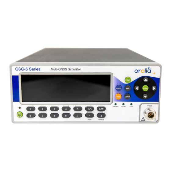
3.1 Front Panel Front Panel All GSG-5/6 simulators have similar front panels. On the right side are the controls used for managing scenario execution and for display navigation . At the bottom are the numeric keys used to input scenario parameters and other configuration. Figure 3-1: GSG front panel There are three status indicators on the front panel. -
Page 43: Description Of Keys
3.1 Front Panel 3.1.1 Description of Keys 3.1.1.1 Power ON/OFF key is a toggling secondary power switch. Part of the instrument is always ON as long as power is applied, this standby condition is indicated by a red LED above the key. This indicator is consequently not lit while the instrument is in operation. -
Page 44: View
3.1 Front Panel 3.1.1.6 View When running a scenario, press view to toggle between the available views. In the main menu , pressing view will act as a shortcut to the configuration display of the currently selected scenario. In the Options menu, press view to make a selection (same as enter... -
Page 45: (Hold)
3.2 Rear Panel When configuring or executing a scenario, press +/– (format) to change the coordinate ECEF format between geodetic coordinates, and format. In scenario execution, View 2/5 and higher, press +/– (format) to switch between fre quency bands (L1, L2 and L5). 3.1.1.13 [.] (hold) Use the "DOT"... -
Page 46: The Gsg Main Menu
3.3 The GSG Main Menu External Reference Input : Can be selected as a reference via the Interface and Reference menu. External Trigger Input : Optional signal input for scenario triggering. GPIB Connector : The address is set in the Interface and Reference menu. Ethernet Connector : Data communications port used with TCP/IP networks. -
Page 47: Start" Menu
3.4 "Start" Menu Name of the current scenario Scenario start date Transmit RF power (see also: "Setting Transmit Power" on page 107) Trajectory shape Scenario Current Position (latitude/longitude) In the upper right-hand corner, abbreviations may be shown: REM : remote commanding EXTREF : external reference clock is selected in the Options menu ARM : the unit is waiting for a trigger to start the scenario HOLD : the movement along the trajectory is paused... -
Page 48: Scenario Start Variations
3.4 "Start" Menu Figure 3-4: Scenario start variations – Flowchart 3.4.1 Scenario Start Variations Hold before manual start Once you pressed , or (with the Start main menu option highlighted), the GSG unit start enter requires some time to launch the scenario (the delay depends on the size/complexity of the scenario data). -
Page 49: View 1/X
3.4 "Start" Menu Figure 3-5: Views displayed during scenario execution To display the views in successive order, press the view key. In the lower right corner e.g., View 2/6 may be displayed, indicating the current view/total number of views. The total number, and content of views depends on the number of signals used in the scenario. - Page 50 3.4 "Start" Menu In view : Shows the abbreviation of each satellite system, followed by its number of satel lites in view/GSG channels reserved. Satellite system abbreviations are: GP : GPS GL : Glonass GA : Galileo BD : BeiDou IR : IRNSS QZ : QZSS : Pseudo-Range Number (satellite identifier).
- Page 51 3.4 "Start" Menu iUG , for unmodulated GPS interference signal iUE , for unmodulated Galileo interference signal iUC , for unmodulated BeiDou interference signal iUJ , for unmodulated QZSS interference signal iUx , for unmodulated GLONASS interference signal, where ‘x’ is the frequency slot ranging from -7 to 6 iSg , for sweeping GPS interference iSr , for sweeping Glonass interference...
-
Page 52: Last View
3.5 "Select" Menu Adjustments to dbALL are saved to the transmit power so that when a scenario is run next time the power is as desired. Changing the Transmit Power setting becomes effective immediately, and also impacts noise generation levels (if in use – available with GSG-5, GSG-55, GSG- 56 and GSG-62, 63, and 64). - Page 53 3.5 "Select" Menu can re-configure to adapt them to your needs. You can also create your own scenarios using the optional GSG StudioView Software. Prior to running a scenario, you have to select it from the list of scenarios installed on the GSG unit: In the Main Menu , highlight Select using the arrow...
-
Page 54: Start Time
3.5 "Select" Menu "Ephemeris" on page 44 "Leap Second" on page 49 "Event Data" on page 50 "Antenna Settings" on page 55 "Advanced Configuration Options" on page 57 "Multipath Signals" on page 57 "Interference signals" on page 60 "Base station" on page 62 "Environment models" on page 64 "Atmospheric model" on page 67 "Satellite Configuration"... -
Page 55: Duration
3.5 "Select" Menu NTP real time and downloaded Ephemeris Using NTP as start time in conjunction with Ephemeris set to Download is subject to licensing options, as it requires the Simulate Now option to be present. In this configuration, the GSG unit will simulate the sky as it is in that start position at current time. -
Page 56: Latitude, Longitude, Altitude
3.5 "Select" Menu Looping : The scenario will be replayed infinite times, re-starting every time after its set duration has expired. For this mode, the trajectory should be loop-shaped , i.e. have the same start/end point. Otherwise, an error will likely be thrown once the receiver- under- test upon the first replay is moved from the end point to the start point in an unrealistically short time. -
Page 57: Predefined Trajectories
: “The UE [User Equipment, (Spectracom)] moves on a rectangular trajectory of 940 m by 1440 m with rounded corner defined in figure 1. The initial reference is first defined followed by acceleration to final speed of 100 km/h in 250 m. -
Page 58: User-Created Trajectories
Even if the RSG Option (OPT-RSG) is not installed on your GSG, and you can therefore not run scenarios in real time, you can still use the Spectracom-proprietary RSG format by up-loading RSG trajectories onto your GSG unit. The RSG format is further described under "RSG Com mand Reference"... - Page 59 3.5 "Select" Menu NMEA time-stamp. All other timestamps in the NMEA trajectory will be transformed accord ingly, thus keeping the relative position/times in the NMEA trajectory intact. A given NMEA trajectory can be replayed in any GPS time frame, utilizing any earth coordin ates by specifying the desired start time and start position in the scenario.
-
Page 60: Ephemeris
3.5 "Select" Menu Skipped epochs Note: One GSG epoch equals a 100 ms block of time. The navigation receiver warning field will always be verified. An epoch will be skipped if… …the field value is ‘V’, or …there is no date/time data, or …there is no position data. -
Page 61: Default Ephemeris
3.5 "Select" Menu YUMA files GPS and QZSS almanac data may optionally be provided in the form of (for details, see below). In addition, SBAS message files are also supported (see "SBAS Satellites" on page 77 and "User-Uploaded Ephemeris" on the next page below for more details). Under the menu item Select >... -
Page 62: Download Ephemeris
3.5 "Select" Menu 3.5.5.2 Download Ephemeris The user can let the unit automatically download navigation data from official websites. The navigation data, files and GLONASS almanac files are retrieved from the same sites as brdc mentioned under "Default Ephemeris" on the previous page. For this feature to work, the following requirements must be met: The GSG unit must have access to the Internet. - Page 63 3.5 "Select" Menu In the event that dates for the user-specified data do not match the scenario’s start time, then GSG will transform the start time in order to resolve the conflict. If a satellite system (e.g., GPS, or Galileo) is selected (i.e., number of satellites selected is not 0) and no navigation files are selected for that particular satellite system, then GSG will use default data for that satellite system.
- Page 64 3.5 "Select" Menu The scenario is restricted to start times within this range. If a scenario runs beyond this range of time, no new satellites will be added. If the user specifies a start time outside this range, a dia log will advise the user that the ephemeris and almanac are dates are mismatched.
-
Page 65: Leap Second
These can cause the GSG to generate signals that are deemed ‘bad’ by a receiver and may not be used in a fix or for navigation. This data is not main tained by Spectracom and is not guaranteed. Note: The GPS and QZSS almanac files specified must comply with the YUMA file format and match the first 5 characters exactly for field identification. -
Page 66: Event Data
3.5 "Select" Menu Figure 3-7: Leap second configuration The leap second field can be set to -1, 0 or 1, and indicates a future change in the leap second value. While the Δt is set automatically based on information in the used ephemeris data, the value given in the leap second field will impact values related to LSF (Leap Seconds Future). - Page 67 3.5 "Select" Menu 1. TIME {scenario | prn SATID | channel NUMBER} relpower RELPOWER 2. TIME {scenario | prn SATID | channel NUMBER} abspower on|off|ABSPOWER 3. TIME {prn SATID | channel NUMBER} duplicate RELRANGE RELDOPPLER RELPOWER EFFECTIVETIME [CHTARGET] 4. TIME {prn SATID | channel NUMBER} multipath RELRANGE RANGECHANGE RANTEINTERVAL RELDOPPLER DOPPLERCHANGE DOPPLERINTERVAL RELPOWER POWERCHANGE POWERINTERVAL [INSTANCE]...
- Page 68 3.5 "Select" Menu , so that the is aligned with the LSB of STARTBITPOS ENDBITPOS ENDBITPOS HEXSTRING Should > length ( ), the ENDBITPOS-STARTBITPOS+1 HEXSTRING HEXSTRING will be used as a repeating pattern to replace the bits between STARTBITPOS ENDBITPOS Multiple navbits events may be applied to the same message.
- Page 69 3.5 "Select" Menu SFID a subframe ID (with GPSL1 and L2P signals) a message type (with L2C and L5 signals) a frame ID (with Glonass) PAGEID a page ID (with GPSL1 and L2P signals) 0 (not relevant) when the subframe ID is 1-3 0 (not relevant) with L2C and L5 signals a string idID (with Glonass).
- Page 70 3.5 "Select" Menu 10.0 channel 6 duplicate 30.0 -0.01 -8.3 0 11.0 channel 6 multipath 35.0 0.01 1.0 0.0 0.0 0 -10.0 0.0 0 11.0 prn G9D multipath 25.0 0.01 1.5 0.0 0.0 0 -15.0 0.0 0 12.0 prn G1 navbits L1CA 1 0 77 77 1 0 0 170.0 channel 6 delete 180.0 channel G9D delete 1.0 seconds into the scenario the power level of the satellite in channel 7 will be atten...
-
Page 71: Antenna Settings
3.5 "Select" Menu E X A M P L E : The output power of channel 1 is set to -142.0 dBm, while all other channels are transmitted with an output power of -147.0 dBm. 4.0 scenario abspower -147.0 4.0 channel 1 abspower -142.0 Note also that settings of events overrule the Transmit power setting specified abspower... -
Page 72: Lever Arm
3.5 "Select" Menu GPS-703-GGG : Gain pattern approximates Novatel’s GPS-703-GGG antenna with max www.novatel.com imum gain of +5.7 dBic. See for details. The format used to describe gain patterns is the FEKO pattern file format version 6.1, Far Field format, File Format 2.0. Gain patterns for various frequencies are to be included in the same file as separate Solution Blocks. -
Page 73: Advanced Configuration Options
3.5 "Select" Menu Figure 3-8: Elevation mask A receiver typically has a higher elevation mask and it will not use any satellite below the elev ation angle of its set mask. The recommended setting is to set the elevation mask of GSG to a value equal or less than that of the device under test. - Page 74 3.5 "Select" Menu Figure 3-9: Multipath signals in urban environment To configure a multipath signal, navigate to Select > Select Scenario > Configure Scenario, View 2/3: Advanced , and specify a number greater than zero for Multipath signals . Note: Your GSG unit requires free channel(s) available, in order to allow for the creation and configuration of a (several) new multipath signal(s).
- Page 75 3.5 "Select" Menu Range Offset : The Range (or: Code) offset in meters. For a multipath signal this value should typ ically be positive, meaning that the travelled distance of the signal will be longer than that of the original or line-of-sight (LOS) signal. Change : Change in range offset, given in meters / Interval Interval : Specify change interval in seconds to the nearest tenth second.
-
Page 76: Interference Signals
"List of Available Options" on page 197). Spectracom GSG- Series simulators can generate GNSS interference signals to test GNSS receiver performance. To configure an interference signal, navigate to Select > Select Scen ario > Configure Scenario, View 2/3: Advanced: Interference Signals . - Page 77 3.5 "Select" Menu Figure 3-12: Interference signal type configuration view The interference signal type can be: GPS : L1CA, L1P, L2P, L1P(Y), L2P(Y), GPS carrier, SBAS GLONASS : L1, L2 or GLONASS carrier Galileo: E1, E5a, E5b or a Galileo carrier BeiDou : B1,B2 or BeiDou B1,B2 carrier signal QZSS : L1CA or QZSS L1 carrier signal.
-
Page 78: Base Station
3.5 "Select" Menu Frequency offset The frequency offset refers to nominal frequency of the selected signal/frequency slot. Power, Position It is possible to simulate a location-based jamming signal by specifying a position for it. Loca tion-based jamming simulation utilizes the jamming signal power, and position to calculate the distance from the simulated position, applying the path loss formula given earlier in this doc ument (see "Signal Power Level Considerations"... - Page 79 3.5 "Select" Menu same satellites the mobile receiver ("rover") does, and in real- time transmits corrective pos itioning data to the receiver in the rover via a radio transmission stream. The Base station feature can only be enabled with GSG 6-Series units that have the Real-Time Kinematics Option installed (OPT-RTK, see "List of Available Options"...
-
Page 80: Environment Models
GSG can successfully handle vehicle models with up to 130 triangles. Models should be optim ized for a low polygon count. The triangle count is limited to a total of 300 for the combined environment and vehicle models. For additional information, see the Spectracom Technical Note Vehicle Modeling Propagation Environment Models Built-in signal propagation models can be used to simulate multipath propagation in rural, sub- urban and urban areas. - Page 81 3.5 "Select" Menu M.1225, “ Guidelines for evaluation of radio transmission technologies for IMT-2000 ” (see Section 2.1.4 Parameters of the wideband models). The document is available on the ITU website http://www.itu.int/rec/R-REC-M.1225/en The ITU model corresponds to a tapped-delay line structure with a fixed number of taps: 3 taps in rural and sub-urban environments and 5 taps in an urban environment.
- Page 82 3.5 "Select" Menu The Propagation environment is defined by the environment type (open/rural/sub- urban/ urban) and three parameters: Open sky limit, Obstruction limit and NLOS probability. Default values for the parameters in each environment type are given in the table below. The Open environment type is the default, meaning that all satellites assume free-space propaga tion.
-
Page 83: Atmospheric Model
3.5 "Select" Menu It takes 1 minute to create multipath taps during simulation. Therefore the time interval between switching the environment model should be more than one minute. The Event must be stated without parameters, or alternatively scenario propenv with all three parameters specified. Valid ranges for the parameter values are: : 0.0 to 90.0 (degrees) OPENSKYLIMIT... - Page 84 3.5 "Select" Menu Note: The GSG also supports simulation of ionosphere delays using files in the IONEX format. Tropo model A number of tropospheric models are supported by the device. These are: Saastamoinen model. The model is based on Saastamoinen, J., 'Atmospheric Correction for the Troposphere and Stratosphere in Radio Ranging of Satellites,' The Use of Arti ficial Satellites for Geodesy, Geophysics Monograph Series, Vol.
-
Page 85: Satellite Configuration
3.5 "Select" Menu Figure 3-18: Tropospheric delay vs. elevation angle 3.5.10 Satellite Configuration Depending on the model and configuration of your GSG unit, and the scenario chosen, several satellite systems can be simulated in a scenario, each of which you may want to configure in accordance with the requirements for your receiver-under-test. -
Page 86: Satellite Systems
3.5 "Select" Menu Figure 3-19: GPS satellite configuration To access the first satellite configuration view, navigate to Select > [Select scenario] > Con figure scenario: View 3/3 . The following satellite-relevant settings can be configured: Satellite System , e.g., GPS, Glonass (see "Satellite Systems" below) Number of satellites simulated for a given satellite system (see "Number of Satellites"... -
Page 87: Number Of Satellites
3.5 "Select" Menu BEIDOU China; regional system (Asia); planned global expansion; open system QZSS Japan; regional system IRNSS India; regional system 3.5.10.2 Number of Satellites The maximum number of satellites to be simulated by GSG in a given scenario is specified sep arately for each available GNSS system. - Page 88 3.5 "Select" Menu Frequency Bands Constellation L2/L2C Glonass Galileo BeiDou For multi-frequency, multi-constellation testing it is suggested to test any of the constellations, fre quency bands, or any combination together. The following frequency bands can be generated (GSG-configuration dependent): For GPS: L1CA P(Y): Pseudo encryption For Glonass:...
-
Page 89: Satellite Constellations
3.5 "Select" Menu SAIF Active Signals Frequency bands can be turned ON/OFF separately, so as to configure which types of RF sig nals specific to each supported satellite system shall be active/inactive when a scenario is run ning. Depending on the configuration of your GSG unit, all of the frequency bands listed above can be turned ON/OFF. - Page 90 3.5 "Select" Menu Note: The functionality described below only applies to Glonass . Other installed satellite systems, such as Galileo, still have their first generation of satel lites in orbit. GSG offers three options to configure satellite constellations: The Default setting refers to the constellation state for April 22, 2015. Constellation-wide setting of the satellite generation, e.g., by setting all GPS satellites to Block IIR-M : Figure 3-20:...
- Page 91 3.5 "Select" Menu Figure 3-21: GPS Constellation configuration (StudioView) This functionality may be required for the configuration of scenarios taking place in the past, or 'What-if' scenarios. Consider the following when configuring satellite constellations: The selected satellite constellation will impact the navigation message to mimic the type of simulated satellite.
-
Page 92: Encryption
3.5 "Select" Menu For Glonass: Glonass-K1 Glonass-M (default) 3.5.10.5 Encryption Next to the unencrypted L1 band Coarse/Acquisition Pseudo-Random Noise code (C/A PRN code), the Precise (P), but encrypted Pseudo Random Noise code is used to modulate both the L1, and the L2 carriers. While GSG cannot replicate the encryption, it can emulate, and thus represent the P(Y) code, so as to allow for commercial GPS surveying receivers to be tested for their ability to derive the carrier in a codeless fashion. -
Page 93: Sbas Satellites
3.5 "Select" Menu Enable L1 C/A, L1P, and L2P only: The L1P and L2P will be transmitted without encryption. Enable L1 C/A, L1P, and L2P, and Pseudo P(Y): The P code will be scrambled to mimic a realistic P(Y) signal for use in receivers that can make use of L1/L2 P(Y) signals for codeless applications, or to provide a signal in the band to better emulate the real world. - Page 94 3.5 "Select" Menu GSG can simulate SBAS satellites. Each scenario defines the number of SBAS satellites that should be simulated. There can be 0, 1, 2, or 3 SBAS satellites per scenario. To review/edit the number of SBAS satellites for the scenario chosen, navigate to: Select > [ Select Scenario ] >...
- Page 95 3.5 "Select" Menu messages broadcast by these satellites are downloaded automatically from the following public FTP sites: ftp://131.176.49.48 EGNOS : ftp://ftp.nstb.tc.faa.gov WAAS : MSAS : default MT63 GAGAN : default MT63 GSG logs into these sites anonymously. However, note that both FTP sites are likely to track and record all FTP access, including access by GSG simulators.
-
Page 96: Options" Menu
3.6 "Options" Menu For EGNOS : PRN<prn>_y<YYYY>_d<doy>_h<hour>.ems For WAAS : Geo<prn>_<GPSWeek>_<dayOfWeek> Note: WAAS files do not have a file extension. Should the files downloaded from the ftp server do not meet these format requirements, it will be necessary to rename the files accordingly. QZSS L1 SAIF The QZSS satellites transmit also a SBAS signal, called L1 SAIF. - Page 97 3.6 "Options" Menu The resolution is: 0.1 dBm . Default setting: -125.0 dBm . Note: External Attenuation setting decreases the set Transmit Power level. Note: When the power settings of individual channels are changed during scenario execution (via the > Events menu, or protocol) the power range will be further limited so that the maximum difference between the strongest and the weakest signal is never more than 72 dB.
-
Page 98: Adjusting Transmit Power
3.6 "Options" Menu Table 3-2: Transmit power offsets Constellation Signal Power offset, dB L1 C/A L1 P -3.0 L2 P -3.0 +1.5 -2.5 GLONASS -8.5 +1.5 Galileo +3.5 +3.5 -4.5 Beidou -4.5 L1 C/A QZSS L1 SAIF -2.5 3.6.1.1 Adjusting Transmit Power The term Transmit Power refers to the satellite signal power (signal level) transmitted by GSG during the execution of a scenario. - Page 99 3.6 "Options" Menu Navigate to Options > Transmit Power . Adjust the GPS L1C/A band Ref. power . The power is specified in dBm . The supported range is: Max. -65 dBm … Min. -160 dBm. Select Signals power configuration to open the corresponding menu. Select the desired constellation, and adjust the power for each signal type supported by this constellation.
-
Page 100: Adjusting External Attenuation
3.6 "Options" Menu Absolute power Relative power Signal name Orbit type name (dBm) (dBm) SBAS -131 -2.5 GLOL1 -131 -2.5 GLOL2 -137 -8.5 GALE1 -127 +1.5 GALE5A -125 +3.5 GALE5B -125 +3.5 GALE6 -125 +3.5 BDSB1 MEO* -133 -4.5 BDSB1 IGSO* -133 -4.5... -
Page 101: Adjusting Noise Generation
3.6 "Options" Menu Figure 3-26: Adjusting external attenuation 3.6.1.3 Adjusting Noise Generation GSG-5/6 has the capability to simulate noise on the GPS L1 band. Noise simulation can be a powerful tool for receiver testing, since it allows for a strong signal to be submitted, without jamming the receiver. - Page 102 3.6 "Options" Menu Where k is the Bolzmann’s constant, T is the ambient temperature (in Kelvin), and BN is the bandwidth (in Hertz). For example, an ideal GPS L1 C/A code filter would have a passband of 2MHz, and noise power passed by the filter at a temperature of 290 K would be equal to -141 dBW.
-
Page 103: Signal Generator
3.6 "Options" Menu modifications, and check the SCPI error after each command. If there is a Parameter Conflict error, it would indicate that the unit accepted your command, but due to a conflict with a dif ferent parameter, your parameter value was modified. The conditions under which a Parameter Conflict may occur include the following:... -
Page 104: Signal Type
3.6 "Options" Menu In Signal Generator mode, advanced GSG units can support: GPS, GLONASS, Galileo, BeiDou, SBAS. If equipped with the L2 and/or L5 options, GSG allows the selected satellite(s) to transmit all signals enabled on that satellite. Note: For more information on available GSG models and options, see "GSG Series Model Variants and Options"... -
Page 105: Satellite Id
3.6 "Options" Menu GNSS systems currently supported are: GPS, Glonass, Galileo, BeiDou, and QZSS, and their corresponding signal types. For information on signal types , see also "Frequency Bands and Signal De-/Activation" on page 71. (P(Y)): For more information, see "Encryption" on page 76. Pseudo-encryption : It is possible to generate a signal for any of the SBAS PRNs. -
Page 106: Frequency Offset
3.6 "Options" Menu The transmit power is specified in dBm . The supported range is: Max. -65 dBm … Min. -160 dBm. Note: External Attenuation setting decreases the Max value. For more information, see "Adjusting Transmit Power" on page 82 "Adjusting External Attenuation" on page 84. -
Page 107: Ephemeris
3.6 "Options" Menu 3.6.2.6 Ephemeris If NTP start time is used, the Ephemeris cannot be downloaded, as this data is not available in real time. The simulated range equals to (25.0E-3*speed_of_light), so the 1PPS Out from the back panel would trail the time mark determined from the RF Out signal by 25 ms. If this field is grayed out, it is not applicable for the chosen configuration. -
Page 108: Network Configuration
3.6 "Options" Menu Ethernet GPIB : Set the address here. SCPI-Raw network clients can use a socket connection to port 5025 and send/receive SCPI commands terminated by a newline. The 10 MHz input can also be selected via this view. When it is selected, a small symbol con taining the text EXTREF is displayed in the upper right corner of the GSG display. - Page 109 3.6 "Options" Menu IP autom. , or—when using a static IP configuration—by manually entering the correct DNS address. If in doubt, consult your network administrator about the IP address configuration. NTP Configuration Under Network configuration , you can also—among other things—enable the current time, as delivered by an NTP server, to be used as the Start Time, by setting an NTP Server address.
-
Page 110: Proxy Configuration
3.6 "Options" Menu Note: In order for the ephemeris download to work, the correct DNS address must specified, either by setting Options > Interfaces and Reference > Network > Obtain IP autom. , or—when using a static IP configuration—by manually entering the correct DNS address. - Page 111 3.6 "Options" Menu keys and press ENTER Select files within a directory by using the UP/DOWN arrow keys. To go up one level, select “ ../ ”. To perform an action on a file, first select it, and then use LEFT/RIGHT arrow keys to select the desired action (View, Copy, Rename or Delete).
-
Page 112: Show System Information
3.6 "Options" Menu Note: Directories cannot be created or deleted, and files cannot be copied between directories. Viewing file contents When viewing file contents, the screen can be scrolled up and down, and left and right using arrow keys. To exit the viewer, use the EXIT CANCEL keys. -
Page 113: Restore Factory Defaults
This chapter describes the Calibration menu items. Calibration itself should only be attempted by qualified technicians. Alternatively, you can send your GSG unit to Spectracom to be calibrated. Via the Calibration view, you can: calibrate the unit’s maximum output power, and OXCO frequency view the results of a previous user calibration. - Page 114 Regardless of which oscillator option is installed in your GSG unit: If you are testing GPS timing receivers and are testing the precision of the 1 PPS output, comparing it to the 1 PPS output from your device under test, Spectracom recommends calibration every year.
- Page 115 3.6 "Options" Menu Figure 3-43: User Calibration view During the calibration, the unit generates an unmodulated signal at full power. Maximum RF power is measured by a spectrum analyzer connected to the RF output of your GSG unit. The OCXO DAC value is adjusted according to the frequency measured by the GSG unit from the 10 MHz output at the back panel.
- Page 116 3.6 "Options" Menu BLANK PAGE. CHAPTER • User Manual GSG-5/6 Series Rev. 26...
-
Page 117: Frequent Tasks
This list is constantly being updated. Should you miss a task that is currently included this list, please know: techpubs@spectracom.com . Thank you. The following topics are included in this Chapter: 4.1 Working with Scenarios 4.2 Locking/Unlocking the Keyboard 4.3 Setting Transmit Power 4.4 Accessing the GSG Web Interface 4.5 Using the CLI... -
Page 118: Working With Scenarios
4.1 Working with Scenarios Working with Scenarios The tasks described here are frequently performed in the context of scenario execution and con figuration. 4.1.1 Scenario Start/Stop/Hold/Arm See under: ""Start" Menu" on page 31. 4.1.2 Running a Scenario During scenario execution, you can ... Press view to display up to 6 different views to monitor the execution of your test scen... -
Page 119: Holding A Scenario
4.1 Working with Scenarios 4.1.3 Holding a Scenario Holding a scenario means to temporarily prevent your GNSS receiver from continuing to move along its scenario trajectory (i.e., halting the trajectory), while the simulation continues to run otherwise (time continues to elapse). This can be done manually, by pressing the [.] / hold key, or by using the SCPI command SCENario:CONTrol , see "SOURce:SCENario:CONTrol"... - Page 120 Environment models can be changed to ‘set’ which allows the selection of Environment SketchUp and Vehicle models (created with the third-party tool (a Spectracom Technical Note about Vehicle Modeling using Sketchup is available upon request). The Atmospheric model submenu. Note: Some of the functionality shown is optional.
- Page 121 4.1 Working with Scenarios Note: Some of the functionality shown is optional and may be grayed out. For more information on GSG Options, see "GSG Series Model Variants and Options" on page 194. For each satellite constellation your GSG unit can simulate (e.g., GPS), you can: In the Satellites View (see illustration below), set the maximum...
-
Page 122: Locking/Unlocking The Keyboard
4.2 Locking/Unlocking the Keyboard Note: For a list of all configurable scenario parameters, see ""Select" Menu" on page 36. Note: For the different options on how to start a scenario, see "Scenario Start Variations" on page 32. Locking/Unlocking the Keyboard The keyboard locking functionality prevents any unwanted modifications from being made. When the keyboard lock is engaged, it is not possible to change parameters, or edit scenario execution via the front panel. -
Page 123: Setting Transmit Power
4.3 Setting Transmit Power Open the , and then the command line interpreter (CLI) by clicking the MONITOR icon: Ensure that the CLI is connected to your GSG unit (see "Using the CLI" on page 110). Enter the following command: write SOURce:KEYLOCK:PASSWord [wxyz] The keyboard lock code can be changed at any time. - Page 124 4.3 Setting Transmit Power each individual signal type other than GPS L1 C/A by selecting Signals power configuration . (For more information, see "Adjusting Transmit Power" on page 82.) While the scenario is running — by pressing the key: In Scenario Execution Views 2 to 5/x (see "Scenario Execution Views" on page 32) highlight dBm for all satellites, or press the keys to LEFT/RIGHT arrow...
-
Page 125: Accessing The Gsg Web Interface
4.4 Accessing the GSG Web Interface Accessing the GSG Web Interface To connect to the "The GSG Web UI" on page 168, follow these steps: Determine the IP address of the GSG unit you want to connect to, by navigating to Options >... -
Page 126: Using The Cli
4.5 Using the CLI Figure 4-5: Example GSG Web UI, showing a logged GPS almanac file STUDIOVIEW : Opens the Spectracom website/StudioView web page: www.spectracom.com/Studioview DOCUMENTATION : Opens the Spectracom website/StudioView web page: www.spectracom.com/GSG Documentation REGISTRATION : Opens the Spectracom website/StudioView web page: www.spectracom.com/Registration... -
Page 127: Performing A Receiver Cold Start
4.6 Performing a Receiver Cold Start Click the green PLUS icon in the top-left corner, and enter the name of the new con nection, and its IP address (which can be found under the GSG menu Options > Inter face and Reference . The IP address will be listed under the Network menu item. Test the connection, and click OK. -
Page 128: Leap Second Configuration
4.8 Leap Second Configuration 0100.0000,E Longitude: 01 deg 00.000' E 77.000 Speed over ground: 77 knots Heading: 0.0 degrees true 140715 Date: 14-July-2015 0.9,W Magnetic Variation: 0.9 deg West Positioning system mode indicator: [A = Autonomous] Checksum data, always begins with * One-line trajectories like this can be easily be made by manually creating the desired NMEA files: The example above can be taken as a baseline, then edit speed... -
Page 129: Studioview Tasks
® GSG StudioView™ software for Windows enables you to create and edit scenarios, and per form file management tasks with Spectracom's GSG series GPS/GNSS simulators. While GSG simulators are capable of configuring and running scenarios without the need for ®... -
Page 130: Studioview Tasks
4.9 Studioview Tasks Convert trajectories from CSV, KML, KMZ and GPX files to the required NMEA format Create scenario files (including events and trajectories) without the need to be connected to a simulator. 4.9.1.1 StudioView Tasks This Chapter describes some of the tasks you will likely perform with GSG StudioView: "Installing StudioView"... -
Page 131: Installing Studioview
GSG simulator, no further downloads are required. 4.9.2 Installing StudioView A free 30-day demo version of StudioView can be downloaded from the Spectracom website, see the link below. After the 30-day trial period you need to purchase a StudioView license to activate all features, with the exception of the Uploader , which does not require a license. -
Page 132: Connecting Studioview To Gsg
4.9 Studioview Tasks 4.9.3 Connecting StudioView to GSG StudioView needs to be connected to your GSG unit so that you can up- /download files, record data, or use the GSG web interface. On the GSG side, you can use the Ethernet port, USB port, or GPIB interface to establish the hardware connection. -
Page 133: Updating The Gsg Firmware Via Studioview
It is possible, albeit not recommended, to back out a firmware update by installing the previous version on top. To obtain the firmware updates 2.03, 2.04, and 4.07 please contact Spectracom Support by clicking the Request Ser http://spectracom.com/support#anchor- vice and Product Support link at... -
Page 134: Uploading Studioview Files
4.9 Studioview Tasks progress of the file transfer is displayed. After the file transfer is complete, the actual upgrade operation is made. Finally, the GSG-5/6 unit will reboot with the new firmware installed. The Windows Personal Computer onto which you will download the new firm ware must have GSG StudioView installed on it, and must be connected to your GSG unit e.g., via Ethernet. - Page 135 4.9 Studioview Tasks and update the list. To obtain your GSG's IP address or change the interface type, select Interface and Refer ence from the GSG Options menu: Note: This screen may vary, based on your installed firmware version. Click the Test button to verify the connection: Uploading Firmware In order to update the onto your GSG unit, in the StudioView Uploader , click...
-
Page 136: Transferring Files With Studioview
, first ensure that the scenario file (. file) and any tra scen jectory, event, or navigation file associated with the scenario are stored in the Stu dioView repository. By default this location is: C:\Users\username\Documents\Spectracom\GSG StudioView\Rep- ository Note: username location may depend on your version of the Windows operating system you are using. -
Page 137: Accessing Gsg Remotely Via Studioview
4.9 Studioview Tasks Establish a connection to the GSG unit by clicking . (For details, see "Connecting Stu dioView to GSG" on page 116.) Once a connection has been established, you should see GSG's file/folder tree in the left window, and StudioView's file list in the right window: Double-click on any folder to open it. - Page 138 4.9 Studioview Tasks Navigate to Tools > Web interface , or click the icon. Click to open the Connections Manager tool (for details, see "Connecting Stu dioView to GSG" on page 116.) After setting up the connection, a visual representation of the front panel will appear: You can control the unit as if physically pressing the buttons on the unit.
-
Page 139: Creating A Trajectory In Studioview
4.9 Studioview Tasks The following generic commands are supported (to display this list in the console win dow, type list – clear commands history – clear console screen <resource 1 > – connect to a specific GSG unit connect – disconnect from currently connected device disconnect –... - Page 140 Trajectories generated by means other than (a.) should always realistically reflect the dynamic cap abilities of the type of vehicle in motion e.g., car, aircraft, ship. To this end, Spectracom recommends using ‘smooth’ methods to describe the movements, i.e. changes in acceleration, heading or altitude should be gradual, not sudden or ‘hard’.
- Page 141 4.9 Studioview Tasks 5. .tle (two-line element), as used for space vehicle simulation (see "Trajectory Two-Line Element Format (TLE)" on page 349). Workflow no. 1. is described below – generating a trajectory using StudioView's Trajectory Editor: Using the Trajectory Editor for the First Time To create or edit a trajectory, open the StudioView Trajectory Editor: On a Windows PC, start StudioView.
- Page 142 4.9 Studioview Tasks Hover Icon Usage Tooltip Display/hide the Speed and Altitude chart. Charts panel "Drag only" Drag (pan) in Google Maps™, while avoiding inadvertent insertion of way map mode points. Display the coordinates of the cursor. Cursor coordinates Access the Google Maps Search functionality (enter the name of a location, "Search"...
- Page 143 4.9 Studioview Tasks Enter additional waypoints as needed. Note: To search for particular place on the map, but not set a waypoint (yet), click the Search icon. Note that any previously set waypoints will NOT be lost. Once all the waypoints for the new route are set (you can add waypoints later), click the Route builder button in the lower right corner of the panel.
- Page 144 4.9 Studioview Tasks Table 4-2: Speed conversion table (Note: mph and knots are rounded down.) Note: When changing speed settings, the time values in the Waypoints table will be updated automatically. Note: As noted before, changes to speed, altitude and heading should be gradual and realistic for the type of vehicle simulated.
-
Page 145: Converting A Trajectory In Studioview
Trajectories should always realistically reflect the dynamic capabilities of the type of vehicle in motion e.g., car, aircraft, ship. To this end, Spectracom recommends using ‘smooth’ methods to describe the movements, i.e. changes in acceleration, heading or altitude should be gradual, not sud den or ‘hard’. -
Page 146: Improving A Trajectory
4.9 Studioview Tasks When using coordinates to describe a trajectory, the data must be provided in 10 Hz format and must not contain sudden changes in speed, direction or elevation; GNSS receivers generally are very sensitive to G-force and unrealistic movements will result in the receiver losing track of the signals. Using the Trajectory Converter for the first Time In StudioView, open the Trajectory Converter tool by clicking the icon, or navigate to Tools... - Page 147 4.9 Studioview Tasks In StudioView, open the Trajectory Converter tool by clicking the icon, or navigate to Tools > Trajectory converter : Apply changes to the original trajectory as needed, following the tabs from left to right. The diagram below illustrates some of the parameters. Downsampling Downsampling means decreasing the number of points in a trajectory, so as to make those parts of a trajectory with constant movement parameters as long as possible.
- Page 148 4.9 Studioview Tasks Smoothing Smoothing is used to adjust movements parameters that are critical for the receiver per formance. By changing the smoothing parameters, you can achieve more realistic speed changes and turn abrupt heading changes into more realistic gradual turns. Enable it by check ing the box on the Smoothing tab.
-
Page 149: Creating An Rsg Trajectory With Studioview
, which allows the GSG unit to receive trajectory inform ation in real-time from e.g., a motion simulator or a computer running simulation software. For more information, see https://spectracom.com/products-services/gnss-simulation/real-time-trajectories. 4.9.11.1 Using the RSG Trajectory Editor for the First Time To open the StudioView RSG Trajectory Editor:... - Page 150 4.9 Studioview Tasks To open an existing RSG trajectory: Navigate to File > Open… , or click To create a RSG trajectory: Enter a Start position , and an altitude in meters. Use a semicolon and a space as sep arators: Note that this data actually is not part of the trajectory, it is used only to assign a relative location to the trajectory.
-
Page 151: Rsg Example: Racetrack Pattern
4.9 Studioview Tasks Select the command you want to use, and enter the required parameters. Detailed com mand descriptions can be found in the "SCPI Guide" on page 213. To edit an existing command, double-click it, or click the button. To delete a com mand, use the button. - Page 152 4.9 Studioview Tasks Open the RSG Trajectory editor. Enter a Start position and altitude (m), or leave the default. Add VELOCITY with initial speed and heading. Next, add a KEEP GOING instruction in order to assign a duration to the previous com mand.
-
Page 153: Kepler Orbit
4.9 Studioview Tasks For the turn, select Left , Direction change : 180°, and Duration : 5 minutes. Lastly, repeat all of the steps above to complete the racetrack pattern (replace the head ing with the opposite heading). 4.9.11.3 Kepler Orbit KEPLER orbits are used to build a trajectory for space vehicles. - Page 154 4.9 Studioview Tasks Note: The preferred way to describe space vehicle trajectories are TLE-formatted trajectories, see "Trajectory Two-Line Element Format (TLE)" on page 349. To access the Kepler trajectory dialog window: In StudioView, navigate to the RSG Trajectory Editor. Click Add to open the Command Editor. Scroll down to Kepler orbit parameters and click OK.
- Page 155 4.9 Studioview Tasks Populate the fields. Attach the Kepler trajectory to a scenario (see "Configuring a Scenario" on the next page). The result will look similar to the illustration below: CHAPTER • User Manual GSG-5/6 Series Rev. 26...
-
Page 156: Playing Rsg Scenarios In Studioview
4.9 Studioview Tasks Note: Higher-end GSG models have a sample Kepler trajectory for the ISS pre-installed. 4.9.12 Playing RSG Scenarios in StudioView StudioView's Realtime Scenario Player allows to play RSG scenarios in real-time. To open the Realtime Player, navigate to Tools > Realtime scenario player , or click The player dialog will open: Use the File or Editor radio-buttons to select the source RSG trajectory (.traj file exten sion) for realtime playing. - Page 157 C:\User s\UserName\Documents\Spectracom\GSG StudioView\Repository . You may save your scenario in any other folder, but please note you must also save any tra jectory, event, antenna pattern, or navigation files you may want to include to your scenario in the same folder.
- Page 158 4.9 Studioview Tasks If the current time from the NTP server is used, next the startup will be delayed up to 2 minutes to allow the simulation to load required data. The start time is aligned to the next full GPS minute. The NTP (UTC) timescale is converted to the GPS timescale by a UTC- GPS offset defined in the NTP server settings.
- Page 159 4.9 Studioview Tasks Note: The maximum number of signals depends on your GSG model. The unit will decrease the number of signals specified in the scenario to fit your license options. If Auto is selected, the GSG unit will use maximum number of channels.
- Page 160 4.9 Studioview Tasks By specifying the Elevation mask , you define the satellite-in-view cut-off range. All satel lites which are below this range will be dropped off and replaced with better/higher satellite (if available). For more information, see "Elevation mask" on page 56. You may also add Interference signals and Multipath signals to the scenario.
- Page 161 4.9 Studioview Tasks A vehicle model represents a 3D model of the vehicle. The vehicle model will move with the simulated trajectory. The vehicle model will also follow any pitch/roll/yaw move ments simulated, i.e. if the vehicle rolls by 90 degrees, half of the sky is likely to be blocked by the vehicle itself, depending on vehicle model used.
- Page 162 4.9 Studioview Tasks https://spectracom.com/sites/default/files/document- For more information, see files/Environmental%20Modeling%20with%20GPS%20Simulation.pdf GSG can successfully handle vehicle models with up to 130 triangles and models should be optimized for low polygon count. The triangle count is limited to a total of 300 for the combined environment and vehicle models.
-
Page 163: Defining Events In Studioview
4.9 Studioview Tasks 4.9.13.1 Defining Events in StudioView To make a simulation more realistic, you can introduce events that can change power levels of certain signals, add or modify multipath signals, change the propagation environment, and modify navigation messages. In order to describe an event, you need to specify the event time in seconds counted from the beginning of scenario, and set the event parameters . - Page 164 4.9 Studioview Tasks To set the type of event, choose an option from the Event type drop-down menu: Change absolute power: Defines a power level for a given channel or PRN code. Change relative power: Defines a change in the power level for a given channel or PRN code.
-
Page 165: Adding A Jammer Signal In Studioview
4.9 Studioview Tasks For Channel event, type Duplicate is also available. Editing or Deleting an Event To edit an event, highlight it, then double-click it, or click To delete an event highlight it, then click 4.9.13.2 Adding a Jammer Signal in StudioView It is possible to add a localized jamming signal to a scenario (or several of them), so as to determine the response of a receiver-under-test to a jamming/interference condition. -
Page 166: Spoofing A Signal In Studioview
4.9 Studioview Tasks 4.9.13.3 Spoofing a Signal in StudioView Note: This functionality is used with the VTS System (Vulnerability Test System), which includes a GSG spoofing license. A spoofing test in StudioView exposes the device-under-test not only to the authentic Sky signal, but also to a second signal generated by the Spoofer . - Page 167 4.9 Studioview Tasks Populate the menu fields: Connection: Open the Connections Manager to establish a connection to the device that generates the authentic satellite data (simulated, recorded, or live sky) Scenario: Select a scenario for the "authentic" simulation. Spoofer Connection: Open the Connections Manager to establish a connection to the device that generates the spoofing data (simulated, recorded, or live sky) Scenario: Select a scenario for the "spoofed"...
- Page 168 4.9 Studioview Tasks Receiver Use receiver: [Yes/No] Determine if you want to feed the GNSS receiver data into StudioView during the simulation. COM port: Determine to which port the receiver is connected Automatically start spoofing immediately after position fix: [Yes/No] Determine when to start the spoofing.
-
Page 169: Using Sbas In A Simulation
4.9 Studioview Tasks The chart on the right will visualize the 2D error, as well as the 3D error between the LiveSky position and the receiver-visible position. 4.9.13.4 Using SBAS in a Simulation GSG will select SBAS SV based on their elevation with respect to the user position. When the scenario is running the SBAS satellite positions and speed will be updated with the information found in the SBAS messages. -
Page 170: Record And Playback
4.9 Studioview Tasks MSAS: default MT63 GAGAN: default MT63 GSG uses an anonymous login. However, note that both FTP sites are likely to track and record all FTP access, including access by the GSG-55. The SBAS download starts when the constellation simulation of the scenario has started; not dur ing initialization of the scenario. -
Page 171: Standard Workflow
4.9.14.3 Usage Notes The Record and Playback software is intended for use with a properly licensed GSG. If your GSG needs a Record and Playback license, please contact Spectracom (see "Tech nical Support" on page 198.) The Record and Playback program uses the GSG VISA address to check for a valid license file. -
Page 172: Recording Data With Studioview
4.9 Studioview Tasks USB[board]::manufacturer ID::model code::serial num- ber[::USB interface number][::INSTR] GPIB[board]::primary address[::GPIB secondary address][::INSTR] For more information about the VISA address, please see: http://zone.ni.com/reference/en- XX/help/371361N- 01/lvinstio/visa_ map_ address/ The signal‐to‐noise ratio (SNR) is used to compare the level of a desired signal to the level of background noise. - Page 173 4.9 Studioview Tasks Figure 4-8: StudioView's Data Recorder The Data tab Under the Data tab you decide where the data to be recorded comes from (a GSG unit, or a GNSS receiver), and which data to log: RINEX navigation files RINEX observation files NMEA from GSG unit NMEA from connected receiver (This can be used to record NMEA data for the GSG...
- Page 174 4.9 Studioview Tasks Figure 4-9: Data recorder View window Preparing the Recording of Data Generated by a GSG Unit On the left side of the screen: Check the box GSG unit , then click to configure the connection (for details, see "Con necting StudioView to GSG"...
-
Page 175: Processing Recorded Data For Playback
4.9 Studioview Tasks If so desired, you can not only record the generated data, but also redirect it to a dif ferent serial port of your computer e.g., to consume the data with a third-party applic ation. If applicable, select and configure that port. As an option, the NMEA data can also be redirected to a GSG unit, in order to use it with a device that utilizes real-time NMEA data (e.g., a marine plotter or receiver demo software). - Page 176 4.9 Studioview Tasks The Scenario Generator translates the GGA, RMC and GSV sentences 1 contained in the NMEA into a syntax that is used by GSG scenario, trajectory and event files. These files are required to playback the recorded data on a GSG unit. Note: The GSG unit requires an internet connection to replay the recorded data.
-
Page 177: Editing Rinex Files In Studioview
4.9 Studioview Tasks Populate the following settings: No thermal noise (dBm/Hz) : On the GSG, signal strength is specified in dBm. The Record and Playback generation relies on a decibel offset value. This offset value maps the NMEA signal strength (in dB) to the GSG signal strength (in dBm). An offset value of [‐160] is recommended to begin with. - Page 178 4.9 Studioview Tasks Comments fields of a RINEX file. The Iono Correction tab Under the Iono Correction tab, you can change the values of correction coefficients. The following dialog box will appear if you double-click on a highlighted GPSA or GPSB row: The Time Correction tab CHAPTER •...
- Page 179 4.9 Studioview Tasks The Time Correction toolbar allows you to change the A0 and A1 coefficients, Reference Time and the Continuous Week Number. Double-click a highlighted row to open the following dia log box: The Leap tab CHAPTER • User Manual GSG-5/6 Series Rev. 26...
- Page 180 4.9 Studioview Tasks Under the Leap tab you can change the Leap seconds , Week number , an Day number . The Data tab Under the Data tab you can change the health of satellites. In each cell, you can enter a number directly, or click the Edit button and select a value from the dropdown list: To edit multiple cells at once, select the cells by holding down the Shift or Ctrl key while click ing, and then click the Edit button.
-
Page 181: Transmitting Rtcm Messages With Studioview
4.9 Studioview Tasks 4.9.16 Transmitting RTCM Messages With StudioView The RTCM Transmission 1 function allows to re-transmit RTCM message from the GSG unit to the external receiver. In order to use this function, a virtual Base Station has to be configured (see also: "Base station"... - Page 182 4.9 Studioview Tasks BLANK PAGE. CHAPTER • User Manual GSG-5/6 Series Rev. 26...
-
Page 183: Reference
Reference This Chapter includes reference information, such as listings of default settings, logs, protocols, file formats and error messages. The following topics are included in this Chapter: 5.1 The GSG Web UI 5.2 Messages 5.3 Timing Calibration 5.4 NMEA Logging 5.5 Execution Log 5.6 Saving RINEX Data 5.7 YUMA Almanac File... -
Page 184: The Gsg Web Ui
5.1 The GSG Web UI The GSG Web UI Spectracom GSG Series simulators feature a Web-based user interface (throughout this doc umentation referred to as " Web UI "), accessible via a standard Web browser (e.g., Mozilla Firefox or Internet Explorer) installed on a computer with access to the same network to which your GSG unit is connected. - Page 185 5.2 Messages Could not initialize the keyboard. A possible hardware issue exists. Please contact service. Could not initialize web interface. A possible firmware issue exists. Re-install firmware. If problem persists, then contact service. Scenario is modified. Do you want to save changes using a different name? Scenario configuration has been modified.
- Page 186 5.2 Messages IP address configuration failed. Configuring the Internet Protocol address failed. Please check your network settings and try again. Cannot save unit parameters. Saving of settings failed. Try restarting the device and saving parameters again. If it still fails, then please contact service.
- Page 187 5.2 Messages Please check start date! GPS Start date is invalid in scenario configuration or signal generator. (Note: The earliest allowed start date is 6.1.1980.) Please check the date and correct it. Invalid Rinex file selected. Check that selected navigation data file is a valid RINEX file (only version 2.1 and upwards sup ported).
- Page 188 5.2 Messages Cannot rename directory. Renaming directory is forbidden. No manageable files available. If this happens the device is faulty. Please contact service. Do you want to delete the file? Confirmation request when removing file. Cannot delete file. Removing of file fails. Cannot rename file.
-
Page 189: Timing Calibration
5.3 Timing Calibration Could not start scenario. Restart GSG-5/6. No scenarios available. This message appears when there are no scenarios in the scenarios directory. Reset factory defaults to restore the default scenarios, or transfer your own scenarios from a PC using the Stu dioView software. -
Page 190: Nmea Logging
5.4 NMEA Logging Provided the option is enabled, you can access and modify this file via the StudioView File Manager (> Tools drop-down menu), or the Web UI under the menu item GSG FILES , or by using SCPI file management commands (see "MMEMory:COPY" on page 306). Note: Restoring factory defaults on the unit will also reset this file to the factory default for the unit. -
Page 191: Execution Log
5.5 Execution Log GSV sentences (1 to 4 depending upon the number of SV’s) describe the actual satellites in view. NOTE : In GSV sentences, an SV’s SNR estimate is given based on the following: When noise is ON: SNR = CNo - NF When noise is OFF: SNR = min (56, Channel Power + BN - NF - Lc) Where NF is (“Noise Figure”... -
Page 192: Yuma Almanac File
5.7 YUMA Almanac File Saving RINEX Observation Data It is possible to store RINEX observations of a running scenario. This feature can be enabled using the SCPI command: SOURce:SCENario:OBS <start>,<duration>,<interval> Specifies the number of seconds since scenario start to expire before starting to log <start>... -
Page 193: Rls (Return Link Service)
5.8 RLS (Return Link Service) retrieved from the observations folder, using: the StudioView File Manager the GSG Web UI the SCPI command set. Note: This file will be overwritten every time a new scenario is started, so only the YUMA file for the last run scenario will be available. The almanac file will be empty, if GPS satellites were not included in the latest scenario executed. -
Page 194: Sar Data
5.8 RLS (Return Link Service) As a user you interact with the GSG by inputting the RLM parameters as a SCPI command into the computer; GSG will then take this message and simulate its transmission on the E1 frequency from the satellite to the distress beacon. For more information on SCPI command syntax, and examples, see "SOURce:SCENario:RLM"... -
Page 195: Galileo E6-B/C Signal
5.9 Galileo E6-B/C Signal Issue the RLM command(s), using the Console e.g.: write SOUR:SCEN:RLM 0,8,711888,141509,1025,65536 The submission should be confirmed: OK [no errors] View the received message on the receiver, see the following example: For automated testing e.g., when integrating GSG into a larger test system, a SCPI program can be written. -
Page 196: Pre-Installed Scenarios
5.11 Pre-Installed Scenarios Use 10 MHz input : No Simulate Noise : No RequiredCN0 : 44 NoiseBW : 20.46 NoiseOffset : 0 Scenarios : See "Pre-Installed Scenarios" below. Trajectories : See "Trajectories" on page 40. Events : See "Event Data" on page 50. 5.11 Pre-Installed Scenarios GSG-5/6 units are shipped with a set of predefined scenarios and supporting files. -
Page 197: Default Scenario Satellites
5.12 Default Scenario Satellites Model Scenario Position Start Date GSG-62/63/64 OPT-L2 GPSL1L2Pcode N60°27'24.41", 01/01/2016 E42°7'24.42" 15:00 GSG-62/63/64 OPT-L2 GPSL1L2pseudoY N60°27'24.41", 01/01/2016 E42°7'24.42" 15:00 GSG-62/63/64 OPT-L2 OPT-GLO GPSGLOL1L2pseudoY N60°27'24.41", 01/01/2016 E42°7'24.42" 15:00 GSG-5/55/56/62/63/64 OPT- GPSMP2Static N10°39'0.00", 01/01/2016 W061°27'0.00" 10:02 GSG-5/55/56/62/63/64 OPT- GPSMP4Static N39°54'0.00", 01/01/2016... -
Page 198: Glonass Default Satellite Types
5.12 Default Scenario Satellites 5.12.1 GLONASS Default Satellite Types All satellites default to the GLONASS-M type. Alternatively, you can select GLONASS K1. CHAPTER • User Manual GSG-5/6 Series Rev. 26... -
Page 199: Scenario File Format
5.13 Scenario File Format 5.13 Scenario File Format Scenarios are defined by means of text files which contain a set of keywords and values, as described below. Scenario files used with GSG-5/6 units must follow the described format. All fields are optional and will assume default values if not provided. - Page 200 5.13 Scenario File Format INTEGER GpsSatellites GlonassSatellites INTEGER GalileoSatellites INTEGER INTEGER BeiDouSatellites INTEGER QZSSSatellites IRNSSSatellites INTEGER Startpos DECIMAL degN DECIMAL degE DECIMAL m DECIMAL degN DECIMAL degE DECIMAL m BaseStationPos FILENAME [0|1] | Static | 3GPP | Circle UserTrajectory DECIMAL DECIMAL DECIMAL LeverArm DeltaLSF -1|0|1...
- Page 201 5.13 Scenario File Format 1 | 0 GPSL2P GPSL2C 1 | 0 GPSL5 1 | 0 1 | 0 GPSPY 1 | 0 GLOL1 GLOL2 1 | 0 GALE1 1 | 0 1 | 0 GALE5a 1 | 0 GALE5b 1 | 0 BDSB1 BDSB2...
- Page 202 5.13 Scenario File Format 1 | 0 GPSL2C GPSL5 1 | 0 GPSPY 1 | 0 1 | 0 GLOL1 1 | 0 GLOL2 GALE1 1 | 0 GALE5a 1 | 0 1 | 0 GALE5b 1 | 0 BDSB1 1 | 0 BDSB2 QZSSL1CA...
- Page 203 5.13 Scenario File Format Scenario File Key Parameter Value Comment word StartTime Valid date in the format: Start time in the GPS Time time frame. MM/DD/YYYY Note that seconds must be set to zero. HH:MM:00 When scenario ephemeris data is set to Download, Source then StartTime must be in the past (typically with a 1- Valid range limited to:...
- Page 204 5.13 Scenario File Format Scenario File Key Parameter Value Comment word BeiDouSatellites [-1, 37] Default: 0 Keyword -1 implies 'Auto' – maximum number of Satel lites in view will be simulated. QZSSSatellites [-1, 4] Default: 0 Keyword -1 implies 'Auto' – maximum number of Satel lites in view will be simulated.
- Page 205 5.13 Scenario File Format Scenario File Key Parameter Value Comment word IonoModel Keyword of comma-sep Default: On arated filenames Available keywords:[Off, 'Off' = 'Off' (in Graphical user interfaces) 'On' ='Klobuchar' (in Graphical user interfaces) Tropo Model {'Saastamoinen' | 'Black Selected tropospheric model. model' | 'Goad&Good Default: 'Saastamoinen' man' | 'STANAG' | 'Off' }...
- Page 206 5.13 Scenario File Format Scenario File Key Parameter Value Comment word {SvGlonassM', Example: A space delimited list of Satellite ID specifying what 'SvGlonassK1' } DefaultGlonassSV satellites are mapped to a non-default satellite series. SvGlonassK1 For GLONASS the Satellite ID is built up by the letter 'R' SvGlonassKM R10 R11 followed by PRN number, e.g.
- Page 207 5.13 Scenario File Format Scenario File Key Parameter Value Comment word BDSB2 [0, 1] , where 0 cor Default: 1 ('On') responds to 'Off' , and 1 to 'On' QZSSL1CA [0, 1] , where 0 cor Default: 1 ('On') responds to 'Off' , and 1 to 'On' QZSSL1SAIF [0, 1] , where 0 cor...
- Page 208 5.13 Scenario File Format Scenario File Key Parameter Value Comment word powerOffset [-30.0, 0.0] Specifying power offset in dB. Default: 0 powerChange [-30.0, 0.0] Specifying power offset change in dB / powerInterval. Default: 0 powerInterval [0, 600] Specifying power change interval in seconds. Default: InterferenceSignals The number of interference channels.
- Page 209 5.13 Scenario File Format Scenario File Key Parameter Value Comment word GALE5b [0, 1] , where 0 cor Specifies the type of signal interference responds to 'Off' , and 1 to 'On' BDSB1 [0, 1] , where 0 cor Specifies the type of signal interference responds to ...
-
Page 210: Gsg Series Model Variants And Options
Default: 0 0 0 [-500.0,+500.0] 5.14 GSG Series Model Variants and Options Spectracom GSG Series GNSS constellation simulators and signal generators are available in several different Model configurations, and with numerous Option packages, in order to allow for application-specific customization: CHAPTER •... -
Page 211: Which Gsg Model & Options Do I Have
5.14 GSG Series Model Variants and Options Figure 5-2: GSG options overview 5.14.1 Which GSG Model & Options Do I Have? The model will be displayed in the top-left corner of the Main screen (startup screen). To find out which options are installed on your GSG unit, navigate to Options > Show System Information >... -
Page 212: Gsg Models & Variants
Single-Channel GPS Factory Tester Options for GSG-5: GLONASS GALILEO BEIDOU QZSS Upgrade to 4-channel unit 5.14.2.2 GSG-5 Series Base unit : 4 channels, GPS L1 C/A Options for GSG-5: Upgrade to 8, or 16-channels Upgradable to GSG-6 Series Advanced Feature Set included: SBAS... -
Page 213: Series
5.14 GSG Series Model Variants and Options 5.14.2.3 GSG-6 Series Multi-frequency, Multi-system GNSS constellation simulators: Up to 64 Channels and 4 simultaneous frequencies GPS L1 C/A Includes Advanced Feature Set of GSG-5 GSG-6 Model variants: -62 : 32 channels and 2 freq bands -63 : 48 channels and 3 freq bands -64 : 64 channels and 4 freq bands Options for GSG-6:... -
Page 214: Problems
5.15.1 Technical Support "Support" page To request technical support, please go to the of the Spectracom Corporate website, where you can not only submit a support request, but also find additional technical documentation. Phone support is available during regular office hours under the telephone numbers listed below. -
Page 215: Regional Contact
5.16 License Notices 5.15.1.1 Regional Contact Spectracom operates globally and has offices in several locations around the world. Our main offices are listed below: Table 5-2: Spectracom contact information Country Location Phone China Beijing +86-10-8231 9601 France Les Ulis, Cedex... - Page 216 5.16 License Notices Work that, considered in isolation, are based on the Application, and not on the Linked Ver sion. The "Corresponding Application Code" for a Combined Work means the object code and/or source code for the Application, including any data and utility programs needed for repro ducing the Combined Work from the Application, but excluding the System Libraries of the Combined Work.
- Page 217 5.16 License Notices For a Combined Work that displays copyright notices during execution, include the copyright notice for the Library among these notices, as well as a reference directing the user to the copies of the GNU GPL and this license document. Do one of the following: Convey the Minimal Corresponding Source under the terms of this License, and the Corresponding Application Code in a form suitable for, and under terms that...
- Page 218 5.16 License Notices you may choose any version of the GNU Lesser General Public License ever published by the Free Software Foundation. If the Library as you received it specifies that a proxy can decide whether future versions of the GNU Lesser General Public License shall apply, that proxy's public statement of acceptance of any version is permanent authorization for you to choose that version for the Library.
- Page 219 5.16 License Notices this provision to those domains in future versions of the GPL, as needed to protect the freedom of users. Finally, every program is threatened constantly by software patents. States should not allow pat ents to restrict development and use of software on general-purpose computers, but in those that do, we wish to avoid the special danger that patents applied to a free program could make it effectively proprietary.
- Page 220 5.16 License Notices A "Standard Interface" means an interface that either is an official standard defined by a recognized standards body, or, in the case of interfaces specified for a particular pro gramming language, one that is widely used among developers working in that language. The "System Libraries"...
- Page 221 5.16 License Notices applicable law fulfilling obligations under article 11 of the WIPO copyright treaty adopted on 20 December 1996, or similar laws prohibiting or restricting circumvention of such measures. When you convey a covered work, you waive any legal power to forbid circumvention of tech nological measures to the extent such circumvention is effected by exercising rights under this License with respect to the covered work, and you disclaim any intention to limit operation or modification of the work as a means of enforcing, against the work's users, your or third...
- Page 222 5.16 License Notices You may convey a covered work in object code form under the terms of sections 4 and 5, provided that you also convey the machine-readable Corresponding Source under the terms of this License, in one of these ways: Convey the object code in, or embodied in, a physical product (including a physical dis tribution medium), accompanied by the Corresponding Source fixed on a durable phys ical medium customarily used for software interchange.
- Page 223 5.16 License Notices "Installation Information" for a User Product means any methods, procedures, authorization keys, or other information required to install and execute modified versions of a covered work in that User Product from a modified version of its Corresponding Source. The information must suffice to ensure that the continued functioning of the modified object code is in no case pre vented or interfered with solely because modification has been made.
- Page 224 5.16 License Notices Prohibiting misrepresentation of the origin of that material, or requiring that modified versions of such material be marked in reasonable ways as different from the original version; or Limiting the use for publicity purposes of names of licensors or authors of the material; Declining to grant rights under trademark law for use of some trade names, trademarks, or service marks;...
- Page 225 5.16 License Notices 9. Acceptance Not Required for Having Copies. You are not required to accept this License in order to receive or run a copy of the Program. Ancillary propagation of a covered work occurring solely as a consequence of using peer-to- peer transmission to receive a copy likewise does not require acceptance.
- Page 226 5.16 License Notices If you convey a covered work, knowingly relying on a patent license, and the Corresponding Source of the work is not available for anyone to copy, free of charge and under the terms of this License, through a publicly available network server or other readily accessible means, then you must either (1) cause the Corresponding Source to be so available, or (2) arrange to deprive yourself of the benefit of the patent license for this particular work, or (3) arrange, in a manner consistent with the requirements of this License, to extend the patent license to down...
- Page 227 5.16 License Notices 14. Revised Versions of this License. The Free Software Foundation may publish revised and/or new versions of the GNU General Public License from time to time. Such new versions will be similar in spirit to the present ver sion, but may differ in detail to address new problems or concerns.
- Page 228 2.1 of the License, or any later version. Copyright 2004, The University of Texas at Austin. Some parts of this product use free software released under the terms of MIT/X11 License. Upon request Spectracom will give out source code according to applicable licenses. Contact spectracom.com information can be found at web address: This license applies to GeographicLib, versions 1.12 and later.
-
Page 229: Scpi Guide
SCPI Guide The following topics are included in this Chapter: 6.1 SCPI Guide: Introduction 6.2 Protocol 6.3 Command Reference 6.4 Sensors Command Reference 6.5 RSG Command Reference 6.6 Programming 6.7 Revision History (SCPI Guide) CHAPTER • User Manual GSG-5/6 Series... -
Page 230: Scpi Guide: Introduction
6.1 SCPI Guide: Introduction SCPI Guide: Introduction The SCPI Guide describes the data exchange between a GSG unit and a PC. SCPI (pro nounced: "skippy") stands for Standard Commands for Programmable Instruments . The SCPI standard describes the syntax of commands widely used to communicate with programmable instruments. -
Page 231: Protocol Errors
6.2 Protocol When using, for example, a telnet client to control the unit, it is enough just type commands and press enter to send the command. 6.2.2 Protocol Errors Below is a list of possible errors and their explanations. They can be retrieved using tSYSTem:ERRor[:NEXT]? -100,"Command error"... - Page 232 6.2 Protocol -161,"Invalid block data" . A block data element was expected, but was invalid for some reason (see IEEE-488.2, 7.7.6.2); for example, an END message was received before the length was satisfied. -190,"Execution in progress" . Command not allowed in current state. -191,"Execution not in progress"...
-
Page 233: Command Reference
6.3 Command Reference Command Reference 6.3.1 Common Commands 6.3.1.1 *CLS Clear Status Command common command clears the status data structures by clearing all event registers and *CLS the error queue. Also possible executing of scenario or signal generator is stopped. It does not clear enable registers and transition filters. -
Page 234: Esr
<Manufacturer>, <Model>, <Serial Number>, <Firmware Level>, <Options>. Example SEND: *IDN? READ: SPECTRACOM,GSG-5,163049,V6.0.3,16 SBAS TRAJ TRG FN NOW INTF MP PPS RSG RP Options The first option listed is the maximum number of channels the unit has been licensed for. CHAPTER •... -
Page 235: Opc
6.3 Command Reference SBAS – Satellite Based Augmentation System satellites TRAJ – Trajectories TRG – External Trigger FN – Fixed bandwidth noise VN – Variable Bandwidth Noise (GSG-55 only) INTF – Interference channels MP – Multipath NOW – Simulate Now PPS –... -
Page 236: Opc
6.3 Command Reference starting/arming signal generator SOUR:SCEN:CONT START SOUR:ONECHN:CONT START Example Enable OPC-bit SEND: *ESE 1 Start scenario. *OPC will set the operation complete bit in the status register when the start of scenario is done and it is running. SEND: SOURce:SCENario:CONTrol start;*OPC Wait 5s for the scenario to start. -
Page 237: Rst
6.3 Command Reference preferred, particularly if several consecutive commands are used as a means to count elapsed epochs. For example, checking that the ECEF position command is applied on the next 10 Hz (100 ms) epoch: sour:scen:ecefposition IMMEDIATE,1000.00,2000.00,3000.00 *OPC? sour:scen:ecefposition? Returned format 6.3.1.7 *RST Reset... -
Page 238: Sre
6.3 Command Reference Service Request Enable Register (1 = enable) Weight Enables RQS, Request Service ESB, Event Status Bit MAV, Message Available QUE, Questionable Data/Signal Status EAV, Error Available Not used Device Status Returned format <Integer> Where: <Integer> = the sum of all bits that are set. Example *SRE 1 In this example, the device generates a service request when a message is available in the out... -
Page 239: Tst
6.3 Command Reference requesting service. Returned format <Integer> = the sum (between 0 and 255) of all bits that are true. Status byte Register (1 = true) Weight Name Condition Enabled operation status has occurred. Reason for requesting service. Enabled status event condition has occurred An output message is ready The quality of the output signal is questionable Error available... -
Page 240: System: Subsystem Commands
6.3 Command Reference Example SOURce:SCENario:CONTrol start;*WAI;SOURce:SCENario:LOG? Wait until scenario is running and then request NMEA position. RSG Example SEND: *WAI? SEND: SOURce:SCENario:VELocity 123.400,27.25, 210.8000 SEND: SOURce:SCENario:PRYRate 123.400,-2.0000,2.0000,1.0000 Wait until the next 100 msec interval and issue the following commands. 6.3.2 SYSTem: Subsystem Commands 6.3.2.1 SYSTem:ERRor? -
Page 241: System:reset:factory
6.3 Command Reference No position information is received during the epoch. The default configuration is NOT to flag error. Command Syntax SYSTem:ERRor[:NEXT]? Note commands are only available during scenario execution. If scen SOURce:SCENario ario is not running these error codes are to be returned (for both set and get functions); -191 ,"Execution not in progress". -
Page 242: Source: Subsystem Commands
6.3 Command Reference 6.3.3 SOURce: Subsystem Commands Commands are available at all times, but note that some commands behave differently depend ing on the status of the unit. More specifically, commands related to, e.g., power settings will have an immediate effect, but if these commands are called during scenario or signal exe cution, the original settings will be restored when the execution stops. -
Page 243: Source:refpower
6.3 Command Reference Example SEND: SOURce:POWer? READ: -121.3 6.3.3.3 SOURce:REFPOWer Function Changes the absolute power in dBm of the reference signal (GPS L1 C/A). Command Syntax SOURce:REFPOWer <decimal> Notes This command can only be used before starting a simulation. The setting is not stored during scenario or 1-channel mode execution. -
Page 244: Source:refpower
6.3 Command Reference 6.3.3.4 SOURce:REFPOWer? Function Returns current absolute power in dBm of the reference signal (GPS L1 C/A). Command Syntax SOURce:REFPOWer? Example SEND: SOURce:REFPOWer? READ: -121.3 6.3.3.5 SOURce:ABSPOWer Function Changes the absolute power for the given signal type and orbit type. Command Syntax SOURce:ABSPOWer <signal name>,[<orbit type name>,]<power>... -
Page 245: Source:abspower
6.3 Command Reference SOUR:ABSPOWer BDSB1,GEO,-123.2 Both keywords “all”, and “default” can be used together: SOURce:ABSPOWer all,default This command will reset whole power configuration to the default state (reference power and relative power offsets as it is specified in ICDs) 6.3.3.6 SOURce:ABSPOWer? Function Returns the current absolute power in dBm for the given signal type and orbit type. -
Page 246: Source:relpower
6.3 Command Reference If the power is inside the allowed limits, but other RF parameters need to be modified, such parameters are modified and an error about a settings conflict is set. You can use the keyword “all” instead of . -
Page 247: Source:extref
6.3 Command Reference Command Syntax SOURce:EXTREF <ON|OFF> Parameter enum = {ON, OFF} Example SEND: SOURce:EXTREF ON 6.3.3.10 SOURce:EXTREF? Function Get the currently selected clock source. Command Syntax SOURce:EXTREF? Example SEND: SOURce:EXTREF? READ: 6.3.3.11 SOURce:PPSOUTput Function Sets the PPS (pulses-per-second) output of the device. Command Syntax SOURce:PPSOUTput <value>... -
Page 248: Source:ppsoutput
6.3 Command Reference Parameter value = 1, 10, 100, 1000 pulses per second Example SEND: SOURce:PPSOUTput 10 6.3.3.12 SOURce:PPSOUTput? Function Get the current PPS output setting. Command Syntax SOURce:PPSOUTput? Note This feature is not available on GSG-52. Example SEND: SOURce:PPSOUT? READ: 6.3.3.13 SOURce:EXTATT Function... -
Page 249: Source:extatt
6.3 Command Reference If the value is inside allowed limits, but other RF parameters need to be modified, they are mod ified and an error about settings conflict is set. Parameter decimal = [0,30] in dB Example SEND: SOURce:EXTATT 12.2 6.3.3.14 SOURce:EXTATT? Function Query the current external attenuation setting of the unit. -
Page 250: Source:noise:control
6.3 Command Reference Parameter enum = {ON, OFF} Example SEND: SOURce:NOISE:CONTrol ON 6.3.3.16 SOURce:NOISE:CONTrol? Function Get the noise simulation state. Command Syntax SOURce:NOISE:CONTrol? Example SEND: SOURce:NOISE:CONTrol? READ: 6.3.3.17 SOURce:NOISE:CNO Function Set the maximum carrier-to-noise density of the simulated signals. Command Syntax SOURce:NOISE:CNO <decimal>... -
Page 251: Source:noise:cno
6.3 Command Reference Parameter in dB·Hz. A decimal number, within the range [0.0 … 56.0]. Example SEND: SOURce:NOISE:CNO 44.1 6.3.3.18 SOURce:NOISE:CNO? Function Get the current maximum carrier-to-noise density of the simulated signals. Command Syntax SOURce:NOISE:CNO? Example SEND: SOURce:NOISE:CNO? READ: 39.2 6.3.3.19 SOURce:NOISE:BW Function Set the noise simulation bandwidth. -
Page 252: Source:noise:bw
6.3 Command Reference Parameter Noise simulation bandwidth in MHz:, Decimal number in range [0.001 … 20.46]. Example SEND: SOURce:NOISE:BW 18.001 6.3.3.20 SOURce:NOISE:BW? Function Get the noise simulation bandwidth. This command is only available with GSG-55 units. Command Syntax SOURce:NOISE:BW? Example SEND: SOURce:NOISE:BW? READ:... -
Page 253: Source:noise:offset
6.3 Command Reference Note Setting not stored during scenario or 1-channel mode execution. This command is only avail able in GSG-55. Parameter Noise frequency offset in MHz. A decimal number within the range [-10.23 … 10.23]. Example SEND: SOURce:NOISE:OFFSET 2.0 6.3.3.22 SOURce:NOISE:OFFSET? Function Get the frequency offset (in MHz) of the simulated noise from the GPS L1 center frequency. -
Page 254: Source:onechn:control
6.3 Command Reference Parameter enum {START,STOP,ARM} Example SEND: SOURce:ONECHN:CONTrol start 6.3.3.24 SOURce:ONECHN:CONTrol? Function Query the current state of the Signal Generator. Meaning of returned values is the following: START : Signal Generator is started and running STOP : Signal Generator is stopped and thus not running WAIT : Signal Generator delays startup for 2 minutes to allow the simulation to load required data. -
Page 255: Source:onechn:satid
6.3 Command Reference 6.3.3.25 SOURce:ONECHN:SATid Function During RF generation 1 , modify the current signal mode. While GSG is not generating RF, set & store the 1-channel mode satellite identifier and signal mode. While GSG is not generating RF, modify the current signal mode. Command Syntax (while not generating RF) SOURce:ONECHN:SATid <signal_mode_letter><gnss_letter><integer>... - Page 256 6.3 Command Reference The syntax to be used while GSG is not generating any RF allows to omit the signal_ parameter and instead specify only the parameter fol mode_letter gnss_letter lowed by an integer. In such case, a modulated signal mode is assumed. parameter: integer If the signal mode is modulated or PRN, the parameter <...
-
Page 257: Source:onechn:satid
6.3 Command Reference Examples (used while the unit is generating RF, e.g. executing a scenario) Set signal mode to unmodulated mode: SEND: SOURce:ONECHN:SATid U Set signal mode to PRN: SEND: SOURce:ONECHN:SATid P Set signal mode to modulated mode: SEND: SOURce:ONECHN:SATid M 6.3.3.26 SOURce:ONECHN:SATid? Function Query the 1-channel mode satellite identifier. -
Page 258: Source:onechn:starttime
6.3 Command Reference Notes If several signal types are selected with either or via SOURce:ONECHN:SIGNALtype menus, then the returned value may have several satellite identifiers separated by comma. If the transmission of data message is disabled, the satellite identifier is preceded by the letter “P”. -
Page 259: Source:onechn:starttime
6.3 Command Reference Example SEND: SOURce:ONECHN:STARTtime 23/11/2010 12:45 6.3.3.28 SOURce:ONECHN:STARTtime? Function Query 1-channel mode start time. Command Syntax SOURce:ONECHN:STARTtime? Example SEND: SOURce:ONECHN:STARTtime? READ: 23/11/2010 12:45 6.3.3.29 SOURce:ONECHN:EPHemeris Function Set & store 1-channel mode ephemeris files to be used (use this command only while the unit is not generating any RF). -
Page 260: Source:onechn:ephemeris
6.3 Command Reference SOURce:ONECHN:EPHemeris brdc0020.09n7 SEND: SOURce:ONECHN:EPHemeris Geo133_1736_01 6.3.3.30 SOURce:ONECHN:EPHemeris? Function Query 1-channel mode ephemeris files. Command Syntax SOURce:ONECHN:EPHemeris? Example SEND: SOURce:ONECHN:EPHemeris? READ: Default 6.3.3.31 SOURce:ONECHN:FREQuency Function Set & store 1-channel mode frequency offset (use this command only while the unit is not gen erating any RF). -
Page 261: Source:onechn:frequency
6.3 Command Reference SOURce:ONECHN:FREQuency -54 SEND: SOURce:ONECHN:FREQuency 4.345 MHz 6.3.3.32 SOURce:ONECHN:FREQuency? Function Query 1-channel mode frequency offset in MHz. Command Syntax SOURce:ONECHN:FREQuency? Example SEND: SOURce:ONECHN:FREQuency? READ: 4.345 6.3.3.33 SOURce:ONECHN:SIGNALtype Function Sets signal(s) to be simulated (use this command only while the unit is not generating any RF). Signal type consists of comma separated list of signal names, as described under “Parameters”... -
Page 262: Source:onechn:signaltype
6.3 Command Reference panel those signals were ignored and not set. As of firmware version 7.0.1 any incompatible signal results in whole command failure so that no signal is set. Parameters – GPSL1CA,GPSL1P,GPSL1PY, GPSL2P,GPS L2PY for GPS <String> – GLOL1,GLOL2 for GLONASS <String>... -
Page 263: Source:onechn:losdynamics:settings
6.3 Command Reference SOURce:ONECHN:SIGNALtype? READ: GPS L1CA,GLOL1,GALE1,BDSB1,QZSSL1CA,IRNSSL5 6.3.3.35 SOURce:ONECHN:LOSDynamics:SETtings Function Set the line of sight dynamics parameters for the Signal Generator. If the profile is running new parameters are memorized, but will be applied only on profile restart. Command Syntax SOURce:ONECHN:LOSDynamics:SETtings <J>,<A>,<DA>,<DV>... - Page 264 6.3 Command Reference acceleration decrease during the next D seconds. After that the acceleration returns to zero so that a constant velocity is maintained during the next D seconds. The whole process is depic ted in the illustration below. The process is repeated until the profile is stopped. The initial conditions when the profile is started are as follows: Start jerk J = 0 m/s³...
-
Page 265: Source:onechn:losdynamics:settings
6.3 Command Reference Figure 6-1: Jerk [m/s³], acceleration [m/s²], velocity [m/s], and range [m] over time [s] 6.3.3.36 SOURce:ONECHN:LOSDynamics:SETtings? Function Queries line sight dynamics profile parameters previously command. SOURce:ONECHN:LOSDynamics:SETtings Command Syntax SOURce:ONECHN:LOSDynamics:SETtings? Example SEND: CHAPTER • User Manual GSG-5/6 Series Rev. 26... -
Page 266: Source:onechn:losdynamics:control
6.3 Command Reference SOURce:ONECHN:LOSD:SET? READ: 0.005,0.1,20,2 6.3.3.37 SOURce:ONECHN:LOSDynamics:CONTrol Function Starts, restarts or stops the line of sight dynamics profile. This command can only be used while RF is generated. Before starting the profile its parameters must be set using the command. -
Page 267: Source:scenario:load
6.3 Command Reference Return values – the profile is currently active <START> – the profile is not active <STOP> Example SEND: SOUR:ONECHN:LOSD:CONT? READ: STOP 6.3.3.39 SOURce:SCENario:LOAD Function Load the scenario as specified by <string>. Command Syntax SOURce:SCENario:LOAD <string> Note Calling the command will stop any running scenarios. Parameter String identifier of filename Example... -
Page 268: Source:scenario:control
6.3 Command Reference Command Syntax SOURce:SCENario:LOAD? Example SEND: SOURce:SCENario:LOAD? READ: scen01.scen 6.3.3.41 SOURce:SCENario:CONTrol Function Control the execution of the scenario. Command Syntax SOURce:SCENario:CONTrol <START|STOP|HOLD|ARM> Notes The scenario must be loaded beforehand using SOURce:SCENario:LOAD Calling a START command will first automatically stop any running scenarios. HOLD can be used to pause and resume trajectory movement, not the entire scenario. -
Page 269: Source:scenario:control
6.3 Command Reference 6.3.3.42 SOURce:SCENario:CONTrol? Function Query the current state of scenario execution. Meaning of returned values is the following: START : scenario is started and running STOP : scenario is stopped and thus not running HOLD : scenario is running, but the trajectory is on hold WAIT : scenario delays startup for 2 minutes to allow the simulation to load required data. -
Page 270: Source:scenario:propenv
6.3 Command Reference For additional information, see "Propagation Environment Models" on page 64. Command Syntax SOURce:SCENario:PROPenv <URBAN|SUBURBAN|RURAL|OPEN> [,<sky_lim- it>,<obstruction_limit>,<nlos_probability>] Parameter Decimal [0.0,90.0] : elevation above which there is no obstruction. sky_limit Decimal [0.0,90.0] : elevation below which there is no line-of-sight obstruction_limit satellites. -
Page 271: Source:scenario:log
6.3 Command Reference 6.3.3.45 SOURce:SCENario:LOG? Function Get current position as NMEA data, available only when scenario is running. Command Syntax SOURce:SCENario:LOG? Example SEND: SOURce:SCENario:LOG? READ: $GPRMC,181810.000,A,6000.1041,N,2400.0553,E,019.4,284.9,060109- ,,*0B $GPGGA,181810.000,6000.1041,N,2400.0553,E,1,15,0.6,587.0,M,0.0- ,M,,,*0F $GPGSV,4,1,15,23,77.7,192.3,44,20,52.8,132.7,44,32,31.2,117.3,- 44,31,24.6,44.0,44*00 $GPGSV,4,2,15,16,9.2,96.3,44,7,1.1,190.7,44,17,0.5,242.4,44,2,- 17.4,319.9,44*00 $GPGSV,4,3,15,30,6.3,1.2,44,4,46.0,280.1,44,13,51.5,230.8,44,2- 5,19.6,184.5,44*2A $GPGSV,4,4,15,126,22.0,178.8,44,124,21.9,182.9,44,120,14.3,223- .6,44*E4 6.3.3.46 SOURce:SCENario:ADVLOG? Function The Advanced Log feature queries log records of the specified log. - Page 272 6.3 Command Reference Command Syntax SOURce:SCENario:ADVLOG? <logID>[,<filter1>,<filter2>,..., <filterN>] – log identifier that specifies what log data to request <logID> – optional filter expression that allows to include into response only specified <filterX> record types Mechanism When a scenario is running, the GSG unit internally creates log records at predefined time intervals and puts them into a limited-size queue with a FIFO (First In –...
-
Page 273: Source:scenario:advlog:header
6.3 Command Reference example, a group of SAT log records usually contains information about several satellites, so there will be several lines of data – one per satellite, and each line will have the same record and time fields. In the RSG log, movement parameters for the body center and the antenna are created at the same moment. - Page 274 6.3 Command Reference Command Syntax SOURce:SCENario:ADVLOG:HEADer? <logID> — Log identifier that specifies the advanced log for which to obtain the header. <logID> Notes The position of specific field label within the comma-separated line is the same as the position of that field’s value within a response line of the command.
- Page 275 6.3 Command Reference Field label (in response to a Possible field values (in response to a Field meaning “SOURce:SCENario: “SOURce:SCENario:ADVLOG?” query) ADVLOG:HEADer?” query) pitch Pitch, degrees Decimal in range [-180; +180] pitch_rate Pitch rate, Decimal degrees/s roll Roll, degrees Decimal in range [-180; +180] roll_rate Roll rate, degrees/s Decimal...
- Page 276 6.3 Command Reference Field label (in response to a Possible field values (in response to a Field meaning “SOURce:SCENario: “SOURce:SCENario:ADVLOG?” query) ADVLOG:HEADer?” query) acc_u Acceleration vertical Decimal projection, m/s When the , the following fields are available: LogID Field label Possible field values (in response to a (in response to a...
- Page 277 6.3 Command Reference Field label (in response to Possible field values Field “SOURce:SCE (in response to a mean Nario: “SOURce:SCENario:ADVLOG?” ADVLOG:HEA query) Der?” query) Record Integer in range [0; 65535] numeric NAVMSG Always NAVMSG iden tifier time Scen >= 0 ario time, s utc_time...
-
Page 278: Source:scenario:observation
6.3 Command Reference Example: SEND: sour:scen:advlog:head? sat READ: id, SAT, time, utc_time, gps_sow, sat_id, pos_x, pos_y, pos_z, pr_l1, prr_l1, doppler_shift_l1, doppler_shift_rate_l1 6.3.3.48 SOURce:SCENario:OBServation Function Turn on scenario observations. All parameters are seconds. Start is the number of seconds from scenario start. Duration is length of observations from start. -
Page 279: Source:scenario:observation
6.3 Command Reference 6.3.3.49 SOURce:SCENario:OBServation? Function Query scenario observation parameters. Command Syntax SOURce:SCENario:OBServation? Example SEND: SOURce:SCENario:OBS? READ: 10,3600,1 6.3.3.50 SOURce:SCENario:NAV Function Turn ON/OFF RINEX navigation data logging. The generated files are in RINEX 3.0.2 mixed format, so the information for all the simulated constellations/satellites will be written into one file. -
Page 280: Source:scenario:nav
6.3 Command Reference 6.3.3.51 SOURce:SCENario:NAV? Function Query status of RINEX navigation data logging. Command Syntax SOURce:SCENario:NAV? Example SEND: SOURce:SCENario:NAV? READ: 6.3.3.52 SOURce:SCENario:SATid[n]? Function Query the current satellite identifier of channel n. The parameter n can be 1-5 for GSG-52/53, 1- 8 for GSG- 54, 1- 16 for GSG- 55/GSG- 56 and 1- 32/48/64 for GSG- 62/63/64. The returned satellite identifier can be: xx for GPS for example G12 xx for GLONASS, for example R15... -
Page 281: Source:scenario:signaltype[N]
6.3 Command Reference Would the signal be a multipath signal, this is identified by an added character at the end. The satID is returned with a leading timestamp. Command Syntax SOURce:SCENario:SATid[n]? Note Only available during scenario execution. Example SEND: SOURce:SCENario:SATid5? READ: 123.4,R23 6.3.3.53 SOURce:SCENario:SIGNALtype[n]? -
Page 282: Source:scenario:signaltype
6.3 Command Reference L1CA,L2P 6.3.3.54 SOURce:SCENario:SIGNALtype? Function Query signal type of satellite. Signal type consists of comma separated list of frequency bands and codes (CA or P code) for GPS and frequency bands for GLONASS, Galileo, BeiDou, QZSS and IRNSS. Command Syntax SOURce:SCENario:SIGNALtype? <satID>... - Page 283 6.3 Command Reference Note Only available during scenario execution. Parameter satID – GPS, Glonass, BeiDou, QZSS and SBAS are supported, the format is explained under "SOURce:ONECHN:SATid?" on page 241. sigtype – One of the signal types supported by the satellite, allowed values are: For GPS : L1CA, GPSL1CA, L1P, GPSL1P, L1PY, GPSL1PY, L1CAP, GPSL1CAP, L1CAPY, GPSL1CAPY, L2P, GPSL2P, L2PY, GPSL2PY, L2C, GPSL2C, L5, GPSL5 Note:...
- Page 284 6.3 Command Reference For QZSS L1SAIF: message type, where 0 means that the modification is applied on the next message independently of its type For SBAS: message type, where 0 means that the modification is applied on the next message independently of its type pageid –...
-
Page 285: Source:scenario:frequency[N]
6.3 Command Reference 06/10/2013 15:00:24 GPS GPS 23 L1CA repeat 1 sfid 1 pgid 0: 8b0c98374923e24b4108008aaaaab- f5555550d5555543ffff2b31048ca1600ffe3b780634a8 Set all bits to 0 in subframe 3 of GPS L1CA message: sour:scen:navbits IMM,G23,L1CA,3,0,1,300,0,0,0 Set bits 16-119 to 1 in the next QZSS L1SAIF message from satellite J3: sour:scen:navbits IMM,J3,L1SAIF,0,2,16,119,FF,0,1 6.3.3.56 SOURce:SCENario:FREQuency[n]? Function... -
Page 286: Source:scenario:power[N]
6.3 Command Reference Command Syntax SOURce:SCENario:FREQuency? <satID> Note Only available during scenario execution. Parameter For a list of satID satellite identifiers, see "SOURce:ONECHN:SATid?" on page 241. Example SEND: SOURce:SCENario:FREQuency? G32 READ: 123.4,-480.513 6.3.3.58 SOURce:SCENario:POWer[n] Function Sets the power of channel n when the scenario is running. The parameter n can be: 1-5 for GSG-52/53 1-8 for GSG-54... -
Page 287: Source:scenario:power[N]
6.3 Command Reference Parameters Decimal [-160.0,-65.0] dBm, if freqband is not ALL. For ALL, the relative change by which the power setting is to be modified, should be limited to a delta of 100 (e.g., changing a power of -65 dBm to -165 dBm (by -100) and vice versa (+100). FreqBand [L1, L2, L5, ALL] Examples SEND:... -
Page 288: Source:scenario:power
6.3 Command Reference Command Syntax SOURce:SCENario:POWer[n]? [<freqband>] Note Only available during scenario execution. Parameter FreqBand [L1, L2, L5, ALL] Example SEND: SOURce:SCENario:POWer3? READ: 123.4,-119.7 SEND: SOURce:SCENario:POWer2? L2 READ: 124.4,-121.2 6.3.3.60 SOURce:SCENario:POWer Function Set the power of satellite satID when scenario is running. Freqband parameter is optional and can be used when only certain frequency band power of satellite is changed. -
Page 289: Source:scenario:power
6.3 Command Reference Parameter Decimal [-160.0,-65.0] dBm, if freqband is not ALL. For ALL, the relative change by which the power setting is to be modified, should be limited to a delta of 100 (e.g., changing a power of -65 dBm to -165 dBm (by -100) and vice-versa (+100). For a list of satID satellite identifier, see "SOURce:ONECHN:SATid?"... -
Page 290: Source:scenario:freqband:power
6.3 Command Reference SEND: SOURce:SCENario:POWer? R22 READ: 124.4,-121.2 6.3.3.62 SOURce:SCENario:FREQBAND:POWer Function Set the power for a frequency band (all satellites) when scenario is running. Freqband is used to specify the frequency band. The freqband value ALL means that the power for all bands is adjusted by the amount indicated. -
Page 291: Source:scenario:svmodel[N]
6.3 Command Reference Block II, Block IIA, Block IIR, Block IIR-M, Block IIF or Block IIIA for GPS Glonass-M or Glonass-K1 for GLONASS Command Syntax SOURce:SCENario:SVmodel? <satID> Parameter Decimal [-160.0,-65.0] dBm, if freqband is not ALL. For ALL, the limits are [-100,100] dB. For a list of satID satellite identifiers, see "SOURce:ONECHN:SATid?"... -
Page 292: Source:scenario:list
6.3 Command Reference SOURce:SCENario:SVmodel4? READ: Block IIR-M 6.3.3.65 SOURce:SCENario:LIST? Function List possible models which can be used in the scenarios. Note that for ionomodels, the options are limited to ‘ON, OFF’. Command Syntax SOURce:SCENario:LIST? <antennamodels | tropomodels | ionomod- els> Example SEND: SOURce:SCENario:LIST? antennamodels... -
Page 293: Source:scenario:antennamodel
6.3 Command Reference 6.3.3.67 SOURce:SCENario:ANTennamodel? Function Query the antenna model of current scenario. Command Syntax SOURce:SCENario:ANTennamodel? Example SEND: SOURce:SCENario:ANTennamodel? READ: Zero model 6.3.3.68 SOURce:SCENario:TROPOmodel Function Set the tropospheric model for the current scenario. Command Syntax SOURce:SCENario:TROPOmodel <tropomodel> Example SEND: SOURce:SCENario:TROPOmodel Black model 6.3.3.69 SOURce:SCENario:TROPOmodel? Function Query the tropospheric model of the current scenario. -
Page 294: Source:scenario:ionomodel
6.3 Command Reference Example SEND: SOURce:SCENario:TROPOmodel? READ: Saastamoinen 6.3.3.70 SOURce:SCENario:IONOmodel Function Select the ionospheric model to be used in the current scenario. Permitted values are ON and OFF. Command Syntax SOURce:SCENario:IONOmodel <ionomodel> 6.3.3.71 SOURce:SCENario:IONOmodel? Function Query whether the Ionospheric model is used in the current scenario. The command returns: ‘OFF’, if the ionospheric model is not used ‘ON’... -
Page 295: Source:scenario:keepaltitude
6.3 Command Reference SOURce:SCENario:IONOmodel? READ: SEND: SOURce:SCENario:IONOmodel? READ: codg0010.14i,codg0030.14i,codg0020.14i 6.3.3.72 SOURce:SCENario:KEEPALTitude Function This command sets the altitude model setting for the current scenario. The default setting is ON. When the model is active, the units will compensate for the altitude change resulting from the difference between the ENU plane and the ellipsoid model of the earth. -
Page 296: Source:scenario:position Time
6.3 Command Reference Example SEND: SOURce:SCENario: KEEPALTitude? READ: 6.3.3.74 SOURce:SCENario:POSition TIME Function Set latitude, longitude and altitude for the geodetic position (WGS84) as the start position for the loaded scenario, or the current position if the scenario is running. Latitude and longitude are defined using decimal degrees. The altitude is given in meters as alti tude over an ellipsoid. -
Page 297: Source:scenario:position
6.3 Command Reference This command changes duration of the currently loaded scenario, but does not change the scen ario file, so that when you try to edit the scenario, you will see unchanged parameters from the file. Example SEND: SOURce:SCENario:POSition IMM,-77.58895432,43.08332157,168.58 6.3.3.75 SOURce:SCENario:POSition? Function Query the current geodetic position in latitude, longitude and altitude during scenario exe... -
Page 298: Source:scenario:ecefposition
6.3 Command Reference Command Syntax SOURce:SCENario:ECEFPOSition TIME,<- decimal>,<decimal>,<decimal> Note If a scenario is armed and not running yet, an error is returned. Parameter Decimal X Position [-26 500 000.00, +26 500 000.00] meters Decimal Y Position [-26 500 000.00, +26 500 000.00] meters Decimal Z Position [-26 500 000.00, +26 500 000.00] meters TIME must be IMMediate. -
Page 299: Source:scenario:datetime
6.3 Command Reference READ: 0.0,2920791.72, 1300420.26, 5500650.33 6.3.3.78 SOURce:SCENario:DATEtime Function Set the scenario start time as GPS time. Command Syntax SOURce:SCENario:DATEtime <MM-DD-YYYY hh:mm|“NTP”> Note If scenario is running or armed, an error is returned. Parameter String format: MM-DD-YYYY hh:mm:ss.s AAA …where MM=Month {01- 12}, DD=day of month {01- 31}, YYYY=year, hh=hours {00- 23}, mm=minutes {00-59}. -
Page 300: Source:scenario:datetime
6.3 Command Reference 6.3.3.79 SOURce:SCENario:DATEtime? Function Query the Date, Time and Timescale of the running scenario or the start time of the loaded scenario. The default timescale is GPS. However, the user can optionally provide a parameter to convert the current Date and Time of the running scenario to various timescales including GPS, UTC, BeiDou, QZSS, Galileo, GLONASS, EGNOS Network Time and WAAS Network Time. -
Page 301: Source:scenario:rtcm
6.3 Command Reference 6.3.3.80 SOURce:SCENario:RTCM? Function Queries for the latest RTCM messages (update rate of 1Hz). Returns a hexadecimal string of the latest RTCM messages, as configured. Command Syntax SOURce:SCENario:RTCM? Example (1006 message type read) SEND: SOURce:SCENario:RTCM? READ: D300153EE001038519731F728933157AC40A72ABE4310000061AC0 6.3.3.81 SOURce:SCENario:RTCMCFG? Function Queries the current RTCM configuration for output. -
Page 302: Source:scenario:rtcmcfg
6.3 Command Reference 6.3.3.82 SOURce:SCENario:RTCMCFG Function Sets the RTCM configuration to use. The arguments given identify the RTCM messages to be out putted. Command Syntax SOURce:SCENario:RTCMCFG 3x,<string>[,<string>]… Parameter string - 1002, 1004, 1006, 1010, 1012 and 1033. Example SEND: SOURce:SCENario:RTCMCFG 3x,1004,1006 6.3.3.83 SOURce:SCENario:RLM Function This command supports the Galileo Return Link Acknowledgement Service by sending out a... - Page 303 6.3 Command Reference Galileo Open Service Signal in Space Interface Control For additional information, see the Document Examples Short RLM SOURce:SCENario:RLM 0,satid,int1,int2,int3,int4 Satid = Galileo satellite in view in running scenario Int1,int2,int3 – beacon id – 3x20bits converted to decimal 15 HEX ID ->...
-
Page 304: Source:scenario:duplicate
6.3 Command Reference Long RLM SOURce:SCENario:RLM 1,satid,int1,int2,int3,int4,int5,int6,int7,int8 Satiid = Galileo satellite in view in running scneario Int1,int2,int3: Beacon ID – 3 x 20 bits convertd to decimal 15 HEX ID -> 60 binary bits (3 x 20) –> each 20 bit binary converted to decimal Int 4-8: 4bit message ID, 96 bit parameter data SOUR:SCEN:RLM 1,8,711888,141509,1025,983040,1048575,1048575,10- 48575,1048575... -
Page 305: Source:scenario:duplicate[N]
6.3 Command Reference <integer>[,<satID>] Parameter TIME – As TIME argument only IMMediate is supported. satID – Satellite identifier of the satellite to duplicate Decimal [-999.999,999.999] – Range offset in meters Decimal [-99.999,99.999] – Range Change rate in meters/interval Decimal [0.0,600.0] – Range Interval in seconds Decimal [-99.9999,99.9999] –... -
Page 306: Source:scenario:duplicate
6.3 Command Reference greater than the system can handle and cause the satellites to shutdown due to exceeding the hardware capabilities. The command can also be used to alter multipath configuration settings before the scenario has started. The argument n is then mandatory and specifies which multipath configuration is changed. -
Page 307: Source:scenario:duration
6.3 Command Reference Command Syntax SOURce:SCENario:DUPlicate? <satID> Parameter satID – For a list of satellite identifiers, see "SOURce:ONECHN:SATid?" on page 241. Example Running SEND: SOURce:SCENario:DUPlicate? G3 READ: 6.3.3.87 SOURce:SCENario:DURATION Function Changes the scenario duration before starting the simulation. Command Syntax SOURce:SCENario:DURATION [<mode>,][duration] Parameters is specified in seconds. -
Page 308: Source:scenario:duration
6.3 Command Reference SOUR:SCEN:DURATION FOREVER Set scenario duration to forever. SOUR:SCEN:DURATION 600 Set scenario duration to 10 minutes, executed once. 6.3.3.88 SOURce:SCENario:DURATION? Function Inquires the duration of the scenario ( specified in seconds). <duration> Command Syntax SOURce:SCENario:DURATION? Return Returns pair can be ONCE/FOREVER/LOOPING. - Page 309 6.3 Command Reference If the satID is left out, the parameter is mandatory and specifies that the command it to act on :th multipath satellite configured. Command Syntax SOURce:SCENario:MULtipath[n] <TIME>,<satID>], <decimal>,<decimal>,<decimal>,<decimal>,<decimal>, <integer>,<decimal>,<decimal>,<integer> Notes By leaving out the satID the command can be executed before the scenario has started to alter the scenario configuration.
-
Page 310: Source:scenario:multipath[N]
6.3 Command Reference SOURce:SCENario:MULTIPath IMM,G9,1.0,2.0,3,4.0,5.0,6,7.0,-8.0,9 6.3.3.90 SOURce:SCENario:MULtipath[n]? Function This command returns the multipath settings for the satellite with given satID. If we have several multipath satellites with the same satID the optional parameter can be used to specify that we are interested in the :th duplicate of this satellite. -
Page 311: Source:scenario:delete[N]
6.3 Command Reference 6.3.3.91 SOURce:SCENario:DELete[n] <TIME> Function This command deletes the satellite at channel n. Command Syntax SOURce:SCENario:DELete[n] <TIME> Note Command is allowed only during scenario execution. SBAS and interference channels cannot be deleted. Parameter TIME – As TIME argument only IMMediate is supported. Example SEND: SOURce:SCENario:DELete17 IMM... -
Page 312: Source:scenario:delete[N]
6.3 Command Reference SOURce:SCENario:DELete IMM,G10,G10D,R9D 6.3.3.93 SOURce:SCENario:DELete[n] <TIME>,<satID> Function This command deletes the satellite specified by the given satID string. The optional n parameter allows the n:th duplicate satellite to be deleted rather than the first found. Command Syntax SOURce:SCENario:DELete[n] <TIME>,<satID> Note Command is allowed only during scenario execution. -
Page 313: Source:scenario:clkmdl
6.3 Command Reference Parameters The Clock Model is described by the following parameters: Table 6-1: Clock Model parameters Parameter Unit Range Description >0 Scenario elapsed time when parameters a and a were measured. When t is set, its value must be within ±10 seconds compared to the current elapsed scenario time. -
Page 314: Source:file:type
6.3 Command Reference Parameters t: scenario elapsed time in seconds when the query was handled (and when the bias was calculated). bias: clock bias at time t. : the current clock model parameters Example SOURce:SCENario:clkmdl? Return Format 2.010000E+01,1.899000E+03,1.000000E+01,2.000000E+03,- 1.000000E+01,0.000000E+00 6.3.3.96 SOURce:FILe:TYPe Function This commands are used to transfer a file to the unit. -
Page 315: Source:file:name
6.3 Command Reference Note Command not allowed during scenario execution, and will result in the error code “-190,"Ex ecution in progress"”. 6.3.3.97 SOURce:FILe:NAMe Function This command sends the file name to be used to store the file to the unit. The name shall only contain alphanumeric characters. -
Page 316: Source:file:data
6.3 Command Reference Command Syntax SOURce:FILe:LENgth Note This command not allowed during scenario execution, and will result in the error code “- 190,"Execution in progress"”. The checksum is calculated using the following algorithm, presented here in a Python language example. The array s passed in must be read from a file opened with attributes read and bin ary (rb). - Page 317 6.3 Command Reference Notes The example below depicts the transfer of a file. The first DATA command depicts the transfer. The checksum shown cannot be recreated from the file data because the end of line characters cannot be identified from the text below. A space must separate the DATA command from the “#”...
-
Page 318: Source:keylock:password
6.3 Command Reference 6.3.3.101 SOURce:KEYLOCK:PASSWord Function Changes the password of the front panel lock. The password has to contain only numerical characters and has to be 4-8 digits in length to be valid. Command Syntax SOURce:KEYLOCK:PASSWord <password> Parameter 4-8 numerical characters. Example SEND: SOURce:KEYLOCK:PASSWord 123456... -
Page 319: Source:keylock:status
6.3 Command Reference Command Syntax SOURce:KEYLOCK:STATus <ON|OFF> Parameter enum = {ON, OFF} Example SEND: SOURce:KEYLOCK:STATus ON 6.3.3.104 SOURce:KEYLOCK:STATus? Function Queries the state of the front panel lock. Command Syntax SOURce:KEYLOCK:STATus? Example SEND: SOURce:KEYLOCK:STATus? READ: 6.3.4 Mass Memory Subsystem Commands All Mass Memory Subsystem commands and queries are not allowed during scenario exe “-190,"Execution in progress"”... -
Page 320: Mmemory:cdirectory
6.3 Command Reference The response contains first used bytes then free bytes on device and then list of the files in format <name>,<type>,<size>. Command Syntax MMEMory:CATalog? <dirname> Example SEND: MMEMory:CATalog? events READ: 3145728,72351744,AGPS1e,ASCII,208,AGPS2e,ASCII,110,AGPS3e, ASCII,208,EventAGPS1,ASCII,59,EventAGPS2,ASCII,29,EventAGPS3, ASCII,29,EventAGPS4,ASCII,180,EventAGPS5,ASCII,250,EventAGPS6, ASCII,29,event0,ASCII,146,event007,ASCII,146,event01,ASCII, 1,eventAGPS1,ASCII,61,eventAGPS2,ASCII,30,eventAGPS3,ASCII, 30,eventAGPS4,ASCII,186,eventAGPS5,ASCII,256,eventAGPS6, ASCII,30,events1,ASCII,874,events2,ASCII,384,events3, ASCII,122 6.3.4.2 MMEMory:CDIRectory Function... -
Page 321: Mmemory:data
6.3 Command Reference Command Syntax MMEMory:CDIRectory? Example SEND: MMEMory:CDIRectory? READ: events 6.3.4.4 MMEMory:DATA? Function Get contents of file. At the start of the response is the header e.g., #800001234, containing the information about the length of the file. The first digit after “#” symbol tells how many next sym bols are used to encode the file size. -
Page 322: Mmemory:delete
6.3 Command Reference IonoModel 1 TropoModel Saastamoinen Temperature 15 Pressure 1100 Humidity 50 MinElev 0 NrSBASChannels 2 6.3.4.5 MMEMory:DELete Function Delete a file in device. If <dirname> is omitted, file is assumed to be in current directory oth erwise the file is deleted from <dirname>. Command Syntax MMEMory:DELete <filename>[,<dirname>] Example... -
Page 323: Mmemory:move
6.3 Command Reference 6.3.4.7 MMEMory:MOVE Function Move a file in current directory or directory <srcdir>. Note that moving between directories is forbidden, so <srcdir> must be equal to <dstdir>. Command Syntax MMEMory:MOVE <srcfile>[,<srcdir>],<dstfile>[,<dstdir>] Example SEND: MMEMory:MOVE scen02,scenarios,scen022,scenarios 6.3.5 Network Subsystem Commands 6.3.5.1 NETwork:MACaddress? Function... -
Page 324: Status: Subsystem Commands
6.3 Command Reference 6.3.6 STATus: Subsystem Commands 6.3.6.1 STATus:OPERation:CONDition? Function Reads out the contents of the operation status condition register. This register reflects the state of the GSG operation. Command Syntax STATus:OPERation:CONDition? Returned Format <Decimal data> = the sum (between 0 and 97) of all bits that are true. See table below: Bit Weight Condition Waiting for bus arming... -
Page 325: Status:operation[:Event]
6.3 Command Reference Bit Weight Condition Waiting for bus arming Waiting for triggering and / or external arming Returned Format <Decimal data> Example SEND: STAT:OPER:ENAB 32 In this example, waiting for triggering, bit 5, will set the OPR-bit of the Status Byte. 6.3.6.3 STATus:OPERation[:EVENt]? Function... -
Page 326: Status:questionable:enable
6.3 Command Reference Bit Weight Condition 14 16384 Unexpected command parameter 6.3.6.5 STATus:QUEStionable:ENABle Function Enable the Questionable Data/Signal Status Reporting by setting the enable bits of the status questionable enable register. This enable register contains a mask value for the bits to be enabled in the status questionable event register. -
Page 327: Status:preset
6.4 Sensors Command Reference Returned Format <decimal data> = the sum (between 0 and 16384) of all bits that are true. See the table for STATus:QUEStionable:CONDition 6.3.6.7 STATus:PRESet Function Enables Device Status Reporting. This command has an SCPI standardized effect on the status data structures. -
Page 328: Supported Sensor Types
6.4 Sensors Command Reference forward/backward left/right up/down , as well as the rotations around the three perpendicular axes: pitch roll. All sensors are initially mounted so that at start of the simulation the sensor’s coordinate system XYZ is aligned with the user's ENU system (East, North, Up). The X axis has a positive direction towards the right side of the sensor. -
Page 329: Accelerometer
6.4 Sensors Command Reference Sensor SENSOR_TYPE keyword Accelerometer ACCelerometer Linear Accelerometer LINearaccelerometer Gravimeter GRAvimeter Gyroscope GYRoscope Odometer ODOmeter 3D Odometer ODOMETER3D, ODO3D 6.4.1.1 Accelerometer The accelerometer outputs acceleration in the XYZ axis. The typical case where the device is flat relative to the surface of the Earth appears as -STANDARD_GRAVITY in the Z axis, and X and Y values as zero. -
Page 330: Odometer
6.4 Sensors Command Reference Sensor data values[0] – Angular speed around the x-axis, in radians/second values[1] – Angular speed around the y-axis, in radians/second values[2] – Angular speed around the z-axis, in radians/second 6.4.1.5 Odometer The odometer sensor keeps track of the total traveled distance. Sensor data values[0] –... -
Page 331: Source:scenario:sensor:register
6.4 Sensors Command Reference 6.4.2.2 SOURce:SCENario:SENSor:REGister? Function Queries if a given sensor is registered. Command Syntax SOURce:SCENario:SENSor:REGister? <SENSORTYPE> 6.4.2.3 SOURce:SCENario:SENSor:UNREGister Function This command unregisters a sensor of a given type, after which the sensor data is no longer out put. Command Syntax SOURce:SCENario:SENSor:UNREGister <SENSORTYPE>... -
Page 332: Rsg Command Reference
6.5 RSG Command Reference 6.4.2.6 SOURce:SCENario:SENSor:NORMalize? SENSOR_TYPE Function Queries if a sensor of a given type is normalized or not. Command Syntax SOURce:SCENario:SENSor:NORMalize? SENSOR_TYPE 6.4.2.7 SOURce:SCENario:SENSor:MAXrange SENSOR_TYPE Function The command specified the max range of a sensor. The minrange equals –maxrange. Command Syntax SOURce:SCENario:SENSor:MAXrange SENSOR_TYPE <decimal>... -
Page 333: Time Parameter
6.5 RSG Command Reference Coordinate Systems Geodetic (Cartesian) Earth Centered Earth Fixed (ECEF) Earth Model WGS-84 Timestamp Time into scenario is given in second and 100 millisecond accuracy. Field Type Default Units Latitude <DOUBLE> decimal degrees Longitude <DOUBLE> decimal degrees Altitude <DOUBLE>... -
Page 334: Rsg Commands
6.5 RSG Command Reference <decimal>, indicating in seconds from Scenario start time when the information is to be applied when using uploaded Scenario/Trajectory files. All commands issued in real-time must use IMM for the TIME parameter. 6.5.3 RSG Commands 6.5.3.1 SOURce:SCENario:POSition TIME Function Set latitude, longitude and altitude for the geodetic position (WGS84) as the start position for... -
Page 335: Source:scenario:position
6.5 RSG Command Reference This command changes duration of the currently loaded scenario, but does not change the scen ario file, so that when you try to edit the scenario, you will see unchanged parameters from the file. Example SEND: SOURce:SCENario:POSition IMM,-77.58895432,43.08332157,168.58 6.5.3.2 SOURce:SCENario:POSition? -
Page 336: Source:scenario:ecefposition
6.5 RSG Command Reference Command Syntax SOURce:SCENario:ECEFPOSition TIME,<- decimal>,<decimal>,<decimal> Parameter Decimal X Position [-26 500 000.00, +26 500 000.00] meters Decimal Y Position [-26 500 000.00, +26 500 000.00] meters Decimal Z Position [-26 500 000.00, +26 500 000.00] meters Note The maximum altitude for normal operation is 18470 meters. (The altitude for Extended Limits is 20200 km.) Example SEND:... -
Page 337: Source:scenario:speed Time
6.5 RSG Command Reference 6.5.3.5 SOURce:SCENario:SPEed TIME Function Sets the vehicle’s speed over ground (WGS84 ellipsoid). Command Syntax SOURce:SCENario:SPEed TIME,<decimal> Parameter Decimal 1D Speed [0.00 to +20000.00] m/s Note The maximum allowed speed for normal operation is 520 m/s. If you want to reverse direction, change heading or use the velocity command. -
Page 338: Source:scenario:heading Time
6.5 RSG Command Reference 6.5.3.7 SOURce:SCENario:HEADing TIME Function Sets the vehicle’s true heading. The heading is expressed in clockwise direction from the true north (WGS84 ellipsoid) representing 0 degrees, increasing to 359.999 degrees. Command Syntax SOURce:SCENario:HEADing TIME,<decimal> Parameter Decimal Heading [0, 359.999] true heading in decimal degrees Example SEND: SOURce:SCENario:HEADing 123.4, 90.000... -
Page 339: Source:scenario:rateheading Time
6.5 RSG Command Reference 6.5.3.9 SOURce:SCENario:RATEHEading TIME Function Sets the heading change rate. Rate is expressed as degrees per second. Heading will be updated each epoch according to the specified constant rate. Next position is calculated using direct rhumb line method (movement with constant heading). Pay attention that specifying con stant heading rate results in non-constant curvature radius, thus it is not suitable for creation of closed-circle trajectories. -
Page 340: Source:scenario:turnrate Time
6.5 RSG Command Reference 6.5.3.11 SOURce:SCENario:TURNRATE TIME Function Sets the rate of turning. Rate is expressed as degrees per second. Next position is calculated using direct orthodromic method (moving along shortest path with non-constant heading). Use this command to simulate movement along arc of circle or closed circle trajectory with constant velocity. -
Page 341: Source:scenario:turnradius Time
6.5 RSG Command Reference 6.5.3.13 SOURce:SCENario:TURNRADIUS TIME Function Sets the radius of turning. Radius is expressed in meters. The next position is calculated using direct orthodromic method (moving along shortest path with non-constant heading). Use this command to simulate movement along arc of circle regardless of velocity changes. Heading rate is varying each epoch, but radius of turning will be constantly equal to value specified. -
Page 342: Source:scenario:velocity
6.5 RSG Command Reference Command Syntax SOURce:SCENario:VELocity TIME,<decimal>,<decimal> Parameter Decimal 1D Speed [0.000 to +20000.000] m/s Decimal Bearing [0, 359.999] true bearing in decimal degrees Note The maximum allowed speed for normal operation is 520 m/s. (For Extended Limits it is limited by interface above.) Example SEND:... -
Page 343: Source:scenario:vspeed
6.5 RSG Command Reference Command Syntax SOURce:SCENario:VSPEed TIME,<decimal> Parameter Decimal 1D Speed [-20000.00 to +20000.00] m/s Note The maximum allowed speed for normal operation is 520 m/s. (For Extended Limits it is limited by interface above.) Example SEND: SOURce:SCENario:VSPEed 123.4,3.15 6.5.3.18 SOURce:SCENario:VSPEed? Function Get the vehicle’s vertical speed. -
Page 344: Source:scenario:enuvelocity
6.5 RSG Command Reference Command Syntax SOURce:SCENario:ENUVELocity TIME,<decimal>,<decimal>,<decimal> Note The local plane of the coordinates will always be re-aligned with ellipsoid surface, meaning the Up-Down velocity can be seen as a velocity with respect to ellipsoid (and not the local plane formed by the position the user was at TIME). -
Page 345: Source:scenario:ecefvelocity
6.5 RSG Command Reference 6.5.3.21 SOURce:SCENario:ECEFVELocity Function Sets the current ECEF velocity in X, Y and Z coordinates when the scenario is running. The Velo city terms are defined in m/s. Command Syntax SOURce:SCENario:ECEFVELocity TIME,<- decimal>,<decimal>,<decimal> Parameter Decimal Velocity X [-20000.00, +20000.00] m/s [-20000.00, +20000.00] m/s Decimal Velocity Y Decimal Velocity Z... -
Page 346: Source:scenario:acceleration Time
6.5 RSG Command Reference 123.4,-4.00,3.00,1.00 6.5.3.23 SOURce:SCENario:ACCeleration TIME Function Sets the 1D acceleration expressed in m/s when scenario is running. Command Syntax SOURce:SCENario:ACCeleration TIME,<decimal> Parameter Decimal 1D Acceleration [-981 to +981] m/s , equivalent to [-100G to +100G] Example SEND: SOURce:SCENario:ACCeleration 123.4,0.50 6.5.3.24 SOURce:SCENario:ACCeleration? Function... -
Page 347: Source:scenario:vaccel Time
6.5 RSG Command Reference 6.5.3.25 SOURce:SCENario:VACCel TIME Function Sets the vehicle’s vertical acceleration. Command Syntax SOURce:SCENario:VACCel TIME,<decimal> Parameter Decimal 1D Acceleration [-981 to +981] m/s , equivalent to [-100G to +100G] Example SEND: SOURce:SCENario:VACCel 123.4,0.50 6.5.3.26 SOURce:SCENario:VACCel? Function Query the vehicle’s vertical acceleration. Command Syntax SOURce:SCENario:VACCel? [<ANTenna|BODYcenter>] Example... -
Page 348: Source:scenario:enuaccel
6.5 RSG Command Reference Command Syntax SOURce:SCENario:ENUACCel TIME,<decimal>,<decimal>,<decimal> Note The local plane of the coordinates will always be re-aligned with ellipsoid surface, meaning the Up-Down velocity can be seen as a velocity with respect to ellipsoid (and not the local plane formed by the position the user was at TIME). -
Page 349: Source:scenario:ecefaccel Time
6.5 RSG Command Reference 6.5.3.29 SOURce:SCENario:ECEFACCel TIME Function Sets the ECEF acceleration in 3-dimensions as Acceleration X, Y, and Z when scenario is run ning. The Acceleration terms are defined in m/s Command Syntax SOURce:SCENario:ECEFACCel TIME,<decimal>,<decimal>,<decimal> Parameter Decimal Acceleration X [-981, +981] m/s , equivalent to [-100G to +100G] Decimal Acceleration Y [-981, +981] m/s , equivalent to [-100G to +100G]... -
Page 350: Source:scenario:pryattitude Time
6.5 RSG Command Reference 6.5.3.31 SOURce:SCENario:PRYattitude TIME Function Sets the Vehicle Attitude in 3-dimensions about the center of mass as Pitch, Roll, and Yaw when scenario is running. The terms are defined in Radians. The pitch argument will be positive when pitching from forward to up. The roll argument is pos itive when rotating from up to right. ... -
Page 351: Source:scenario:dpryattitude Time
6.5 RSG Command Reference 6.5.3.33 SOURce:SCENario:DPRYattitude TIME Function Sets the Vehicle Attitude in 3-dimensions about the center of mass as Pitch, Roll, and Yaw when scenario is running. The terms are defined in Degrees. The pitch argument will be positive when pitching from forward to up. The roll argument is pos itive when rotating from up to right. ... -
Page 352: Source:scenario:pryrate Time
6.5 RSG Command Reference 123.4,-2.0000,2.0000,1.0000 6.5.3.35 SOURce:SCENario:PRYRate TIME Function Sets the rate of change in Vehicle Attitude in 3-dimensions about the center of mass as Pitch Rate, Roll Rate, and Yaw Rate when scenario is running. The Rate of Attitude change terms are defined in Radians per second. -
Page 353: Source:scenario:dpryrate Time
6.5 RSG Command Reference 6.5.3.37 SOURce:SCENario:DPRYRate TIME Functions Sets the rate of change in Vehicle Attitude in 3-dimensions about the center of mass as Pitch Rate, Roll Rate, and Yaw Rate when scenario is running. The Rate of Attitude change terms are defined in Degrees per second. -
Page 354: Source:scenario:kepler Time
6.5 RSG Command Reference 6.5.3.39 SOURce:SCENario:KEPLER TIME Function Sets the Kepler orbit parameters. If a position, speed or acceleration command is sent after the Kepler orbit command, they will overwrite the movements along the Kepler orbit. PRY commands can be applied while the Kepler orbit is active. -
Page 355: Source:scenario:runtime
6.5 RSG Command Reference 1618.6,1.302803E+00,3.130653E+00,9.958063E-04,7.537784E+06,- 1.597289E+00,9.573341E-01,2.961233E+00 6.5.3.41 SOURce:SCENario:RUNtime? Function Queries the current length of time in seconds running a scenario during scenario execution. The time is returned including 3 digits of sub-seconds. The accuracy is equivalent to the system’s internal update rate. Notes If no scenario is running, an error is returned. -
Page 356: Source:scenario:elapsedtime
6.5 RSG Command Reference Parameter String format: MM-DD-YYYY hh:mm:ss.s AAA, where MM=Month {01-12}, DD=day of month {01-31}, YYYY=year, hh=hours {00-23}, mm=minutes {00-59}, ss.s=seconds {00-60} with one decimal of sub-seconds digits. The Timescale AAA= {GPS, UTC, BDS, GAL, GLO, GLO0, ENT, WNT} field supports vari ous GNSS timescales. -
Page 357: Source:scenario:rsgunderflow
6.5 RSG Command Reference SOURce:SCENario:ELAPsedtime? READ: 029d12:34:56.700 GPS 6.5.3.44 SOURce:SCENario:RSGUNDERflow Function Enables or disable RSG underflow detection. It is active once an RSG command comes in. Underflow detection is disabled by default. Command Syntax SOURce:SCENario:RSGUNDERflow <integer> Parameter Integer – Enable or disable {1,0}, respectively. Example SEND: SOURce:SCENario:RSGUNDERflow 1... -
Page 358: Source:scenario:doppler
6.5 RSG Command Reference 6.5.3.46 SOURce:SCENario:DOPPler? Function Queries a satellite’s Doppler for a specific signal supported by that satellite. The signals sup ported vary based on the constellation and scenario configuration. Command Syntax SOURce:SCENario:DOPPler? <satID>,<sigtype> Notes If no scenario is running, an error is returned. If the satellite does not support the signal type, an error is returned. -
Page 359: Source:scenario:prange
6.5 RSG Command Reference -320.51 6.5.3.47 SOURce:SCENario:PRANge? Function Queries a satellite’s range for a specific frequency band supported by that satellite for the sim ulated user position or optionally an RTK base station position. The signals supported vary based on the constellation and scenario configuration. Command Syntax SOURce:SCENario:PRANge? <satID>,<sigtype>,<location>... -
Page 360: Source:scenario:chinview
6.5 RSG Command Reference Example SEND: SOURce:SCENario:PRANge? G19,L1CA READ: 24241628.51 6.5.3.48 SOURce:SCENario:CHINview? Function Queries a comma separated list of values ranging from 1 to 64 which indicate which satellite index values are active in view in the simulated sky. Duplicate and interference channels are ignored. -
Page 361: Source:scenario:svinview
6.5 RSG Command Reference 6.5.3.49 SOURce:SCENario:SVINview? Function Queries a comma-separated list of SatID values which indicate which satellites are in view in the simulated sky. Duplicate and interference channels are ignored. Command Syntax SOURce:SCENario:SVINview? <ALL|GPS|GLO|GAL|BDS|QZSS|IRNSS|SBAS> Note If the scenario is not running, an error is returned. Parameter constellation –... -
Page 362: Source:scenario:svpos[N]
6.5 RSG Command Reference Example SEND: SOURce:SCENario:SVPos8? READ: 13802999.54,18312013.72,13305242.14 6.5.3.51 SOURce:SCENario:SVPos[n]? Function Queries a satellite’s ECEF position using a Satellite ID. The user can specify all satellite types supported including their multipath duplicates by satID. An optional location argument is spe cified to allow use with GSG’s simulating user position or with systems using base station operation. ... -
Page 363: Programming
6.6 Programming Programming 6.6.1 Usage Recommendations 6.6.1.1 Communication Interface It is strongly recommended to use USB in conjunction with RSG. USB is more reliable due to being a dedicated interface as opposed to Ethernet which can be more susceptible to network traffic. -
Page 364: Underflow And Overflow
6.6 Programming *OPC? *OPC? *OPC? *OPC? sour:scen:elapsedTime? *OPC? syst:err? 6.6.1.3 Underflow and Overflow Underflow and overflow errors are signaled by the GSG unit. The possible errors which can be retrieved with the command SYSTem:ERRor[:NEXT]? The relevant error codes are: -193 “RSG command overflow occurred.” -194 “RSG command underflow detected.”... -
Page 365: Limitations
6.6 Programming 6.6.1.5 Limitations Communication over GPIB is not currently working for RSG commands – syn chronization fails. Communication over GPIB is not currently working for RSG commands – syn chronization fails. 6.6.2 Trajectory FILE Format (.traj) Files in the file format can be created with the StudioView RSG Trajectory Editor, but .traj an RSG license is not required to use these commands in a file. -
Page 366: Revision History (Scpi Guide)
6.7 Revision History (SCPI Guide) Create the above-mentioned 3-line file in any text editor. Name the file <any_name>*.tle Select the file for use in a scenario the same way as any trajectory is selected. Revision History (SCPI Guide) SCPI Guide Revision History Description Date 1.0draft N/A... - Page 367 6.7 Revision History (SCPI Guide) SCPI Guide Revision History Description Date 000293 New/updated commands to support 6.3.1 firmware release February 2015 000421 New/updated commands to support 6.4.1 firmware release May 2015 000587 New/updated commands (mainly Propagation Environment) to support Sept 2015 6.5.1 firmware release.
- Page 368 6.7 Revision History (SCPI Guide) BLANK PAGE. CHAPTER • User Manual GSG-5/6 Series Rev. 26...
-
Page 369: Appendix
Appendix The following topics are included in this Chapter: 7.1 Lists of Tables and Images 7.2 GSG User Manual Revision History • APPENDIX User Manual GSG-5/6 Series... - Page 370 APPENDIX Lists of Tables and Images Tables in this document: Table 2-1: Spectracom safety symbols Table 3-1: Propagation environment type parameters Table 3-2: Transmit power offsets Table 4-1: The Trajectory Editor Toolbar Table 4-2: Speed conversion table (Note: mph and knots are rounded down.)
- Page 371 APPENDIX Figure 3-18: Tropospheric delay vs. elevation angle Figure 3-19: GPS satellite configuration Figure 3-20: Assigning one constellation block to all satellites Figure 3-21: GPS Constellation configuration (StudioView) Figure 3-22: Turning pseudo encryption ON/OFF Figure 3-23: GNSS SBAS systems Figure 3-24: Configuring transmit power Figure 3-25: Signals power configuration menu Figure 3-26: Adjusting external attenuation Figure 3-27: Adjusting noise settings in the Transmit Power view...
-
Page 372: Gsg User Manual Revision History
APPENDIX GSG User Manual Revision History Description Date First release. November 2010 Updated to include GSG-55. March 2011 2673 Changes in support of the 2.06 software release. June 2011 2702 Updated address information. October 2011 2769 Added compliance section with updated regulatory information. Addi November tional minor document maintenance. - Page 373 APPENDIX Description Date 3458 Updated to support latest software & software release modifications April 2014 000073 Updated to support latest software & new features July 2014 000194 Updated to support latest software & new features October 2014 000293 Updated to support latest software & new features February 2015 000421...
- Page 374 BLANK PAGE. User Manual GSG-5/6 Series...
- Page 375 Calibration, timing Carrier- noise density Active Signals (C/No) Almanac Almanac file Cold start, GNSS receiver Antenna, compliance Constellations, satellite Antenna, models contact, Spectracom Antenna, specifications Cooling ANTEX armed, unit Atmospheric modeling Desk-Top Setup Attenuation, external Dimensions AutoStart Display symbols Doppler...
- Page 376 INDEX Emissions Electro-magnetic compliance Encryption Interference signal ENU (East, North, Up) Ionosphere model Environmental modeling IP configuration Environmental specifications Ephemeris 39, 44, 78, 91, 104, 115, 142, 153, 161, 183, 198, 240, Jamming Epoch Jamming, jammer Event data EXTREF Keyboard un/-locking Keys, front panel Factory default settings Factory defaults, restore...
- Page 377 INDEX NTP server Numeric keys Safety precautions Satellite ID Satellite systems OCXO DAC value SBAS 48, One-Go, scenario duration Scenario, configuring Options, GSG Scenarios, pre-installed Orientation SCPI, commands SCPI, protocol errors SCPI, syntax Signal generator mode P (pseudo) code Signal type Power requirements Frequency band 60, 75, 81-82, 107, PPS delay...
- Page 378 INDEX Trajectory, NMEA Trajectory, one-line Trajectory, predefined Trajectory, RSG Trajectory, timestamping Trajectory, user-created Transmit power 55, 61, 81-82, 84, 179- Transmit Power, adjust Transmit Power, manage Transmit Power, set Tropospheric model Two-Line Element trajectory format Uploading scenario files UTC-GPS offset Vehicle model Web UI 109, Week number, GPS...
Need help?
Do you have a question about the GSG-5 Series and is the answer not in the manual?
Questions and answers