
Subscribe to Our Youtube Channel
Related Manuals for Spectracom Pendulum PathAlign-R 2200

Summary of Contents for Spectracom Pendulum PathAlign-R 2200
- Page 1 2200/2240/2241 PathAlign-R Test Set for Microwave Antenna Alignment User Manual Test & Measurement by Spectracom www.spectracomcorp.com Part Number PEN9-9990-2240 Manual Revision A June 2011...
- Page 2 Copyright © 2002-2011 Spectracom Corporation. The contents of this publication may not be reproduced in any form without the written permission of Spectracom Corporation. Printed in USA. Specifications subject to change or improvement without notice.
- Page 3 Extended warranties can be purchased for additional Products being returned on an RMA must be properly periods beyond the standard warranty. Contact packaged with transportation charges prepaid. Spectracom no later than the last year of the standard warranty for extended coverage.
-
Page 5: Table Of Contents
Spectracom Corporation PathAlign-R Contents 1 GENERAL INFORMATION ..............1-1 Introduction ........................ 1-1 1.1.1 About this Manual ............................. 1-1 1.1.2 Declaration of Conformity ......................... 1-1 Preparation for Use ....................1-1 1.2.1 Introduction ............................... 1-1 Safety Precautions ..................... 1-1 1.3.1 Introduction ............................... 1-1 1.3.2... - Page 6 PathAlign-R Spectracom Corporation 3 OPERATION ................... 3-20 Introduction ......................3-20 Front Panel ....................... 3-20 3.2.1 Mode Selections ............................. 3-20 3.2.2 Front Panel Path Loss Display ....................... 3-21 3.2.3 LED / LCD Indicators and Annunciators ....................3-21 3.2.4 Connectors ............................. 3-22 Rear Panel .........................
- Page 7 Spectracom Corporation PathAlign-R 4.7.1 NAVSTAR Global Positioning System (GPS) ..................4-39 4.7.2 GPS Reference Information........................4-40 LogView-R Logging Utility Installation ..............4-40 4.8.1 Software Installation ..........................4-40 4.8.2 Windows USB Driver Installation ......................4-40 5 WIRELESS SUPPORTING INFORMATION ........... 5-42 Free-Space Loss .......................
- Page 8 PathAlign-R Spectracom Corporation List of Figures Figure 2-1. Bands 2, 3, & 4 Field Verification Check Test Setup ................2-18 Figure 3-1. Model 2240 Front Panel ........................3-20 Figure 3-2. Model 2240 Rear Panel ......................... 3-23 Figure 3-3. Semflex Chart ............................3-27 Figure 3-4.
-
Page 9: General Information
Spectracom Corporation PathAlign-R 1 General Information 1.1 Introduction The PathAlign-R™ test set is a high performance, complete test solution designed to quickly and accurately optimize the transmission path between two microwave antenna sites. The PathAlign-R directly drives the site’s antennas, allowing the optimization process to be done without the need for on-site radios, complex test equipment, ground technicians, onsite AC power, cell phones, or two-way radios. -
Page 10: Caution And Warning Statements
PathAlign-R Spectracom Corporation 1.3.2 Caution and Warning Statements CAUTION: Shows where incorrect procedures can cause damage to, or destruction of equipment or other property. WARNING: Shows a potential danger that requires correct procedures or practices to prevent personal injury. 1.3.3 Symbols Indicates that the operator should consult the manual. -
Page 11: Static Discharge
PathAlign-R WARNING To insure the integrity of the backpack to the instrument connection, Spectracom provides a stainless steel wire and quick-link connection between the PathAlign-R and the backpack's 'D' ring. This safety wire connection is designed to prevent the possibility of the instrument separating from the backpack and possibly falling, injuring the instrument or tower/ground personnel. - Page 12 PathAlign-R Spectracom Corporation site's antenna. The PathAlign-R's are sold as, and used in, pairs... one at each antenna site. Full duplex voice transmit/receive capability between sites is provided with the enclosed headsets. A Variable Alignment Tone, switch selectable on the front panel, indicates signal strength (path loss) via a variable tone, which can be heard thru the speaker or the headset.
-
Page 13: Specifications
Battery Charger supplied with the PathAlign-R, another charger may damage the PathAlign-R or the battery!). If the charger is lost or damaged a replacement may be purchased from Spectracom. The Record-R Data Logger found in models 2241/2241A allows the user to record and store an individual data record in the instrument's memory with the push of a button. -
Page 14: Receiver
PathAlign-R Spectracom Corporation Deviation: 50-100 kHz Transmit / Receive Offset: 39 MHz (Transmit offset: Switch set to 'Master' =+20 MHz; Switch set to 'Slave' = -19 MHz of the Thumbwheel Frequency setting) Modulation Choice: Voice / Alignment tone, switch selectable on front panel Modulation Input / Output: Headset w/10-foot cable, terminated in a 3.5 mm Plug (Mic &... -
Page 15: Internal Frequency Standard (Txco)
Spectracom Corporation PathAlign-R 1.5.4 Internal Frequency Standard (TXCO) Frequency: 10 MHz Aging Rate / Second: ≤±1 part in 10 (root Allen variance) Aging Rate / Day: ≤±5.1 part in 10 Aging Rate / Year: ≤±7.6 part in 10 after 45 days. -
Page 16: Mechanical
1.5.9 Supplemental Specifications Warranty: One Year Limited Warranty Montreal Protocol: Nil Return ISO 9001: All Spectracom sites are registered to ISO 9001:2008 and are regularly audited and improved to provide you the best possible vendor support. CE (European Union): EN 55011: 1998 w/A1:1999; Group 1 Class B (emissions) EN 61326-1:1997 w/A1:1998 (immunity) 1.5.10... -
Page 17: Record-R Specifications (Model 2241 / 2241A Only)
Spectracom Corporation PathAlign-R DC Output: 15 VDC / 1A DC Connector: 5.5 mm x 2.1 mm Barrel Power connector, 5 foot cord Dimensions (HxWxD): 33 mm x 51 mm x 86 mm (1.3 in x 2.0 in x 3.4 in) Operating Temperature: 0°C to 40°C (32°F to 104°F) - Page 18 PathAlign-R Spectracom Corporation One (1) Weather-resistant Instrument Back-pack One (1) Coax Cable Assembly, SMA (male) to SMA (male), 3 meters One (1) Battery, Rechargeable, Panasonic LSC-2312NC, 12VDC/2.3 Ah, Sealed Lead Acid Battery One (1) Battery Charger, AC MAINS powered, 90 - 264 VAC, with IEC 320 Input connector One (1) AC MAINS power cord (Conforms to IEC 320-3:1987/EN 60 320 and CEE color coding) UL listed type SVT.
-
Page 19: Installation
Check for surface scratches and dents; note the condition of switches, buttons, and connectors (carrying bag, battery, cables, etc.) Should any damaged be detected, notify Spectracom. DO NOT USE THE INSTRUMENT UNTIL INSTRUCTED TO DO SO BY THE FACTORY. -
Page 20: Battery Information
Rechargeable Sealed Lead Acid Camcorder Battery. Do not use any other type or size of battery in the PathAlign-R. Additional batteries are available worldwide or direct from Spectracom. The following information concerning the battery should be observed. 1. Important safety considerations: a. -
Page 21: Mating Connectors
Spectracom Corporation PathAlign-R 2.6 Mating Connectors The Band 1 through Band 4 front panel in/out connectors are coaxial type female Super SMA sparkplug connectors (3.5 mm compatible) with a 50 Ω nominal impedance. The rear panel ’Remote Read-out’ connector is a coaxial type BNC connector (0-2 VDC). The ’External Charger In’... -
Page 22: Sparkplug Installation
Note: If the center conductor of the internal coax (inside the mixer block) is found to be bent, the entire instrument must be returned to Spectracom for repair. Attempting to straighten this center conductor will only deform it and correct mating with the sparkplug will no longer occur. -
Page 23: Optional Additional Checks
Spectracom Corporation PathAlign-R long as the selected frequency stays within the Band 1 range). Repeat this step for each of the other three Bands. 3. Next, set the ’AUDIO Alignment Tone/Voice’ switch to ’Alignment Tone’ and advance the ’AUDIO Volume’ knob until the tone can be heard coming from the front panel speaker (located behind the circular front panel graphic). -
Page 24: Field Verification Check
PathAlign-R Spectracom Corporation 2.9 Field Verification Check The following operational checks of the PathAlign-R may be made by personnel in the field to confirm proper operation of both PathAlign-R units, their coax cables and the waveguide adapters (transitions). This confirmation may be made prior to climbing the towers or whenever an operational confidence check needs to be made in the field, without access to test equipment or electronic technicians. -
Page 25: Band 2, Band 3, And Band 4 Field Verification Check
Spectracom Corporation PathAlign-R 2.9.2 Band 2, Band 3, and Band 4 Field Verification Check 1. First, connect the coax cable to the proper Band connector on each PathAlign-R and then, connect the waveguide adapter (transition) to the other end of this coax making sure that the waveguide adapter band is appropriate for the PathAlign-R’s frequency... -
Page 26: Preparation For Reshipment
Note: Do not reship the battery, carrying case or accessories to the factory, as these items are not covered by the warranty and Spectracom does not repair these items. 2. Wrap the instrument in heavy paper or plastic prior to placing it in the shipping container. -
Page 27: Storage
Spectracom Corporation PathAlign-R 2.11 Storage Remove the battery from the unit. The instrument should be shelved in a reasonably clean environment and protected from dirt and moisture. Storage temperature is -40°C to 71°C (-40°F to 160°F). Place the instrument in its carrying bag or a cardboard container and seal it from dirt and moisture. -
Page 28: Operation
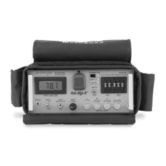
PathAlign-R Spectracom Corporation 3 Operation 3.1 Introduction This section describes the operation of the PathAlign-R, Microwave Antenna Path Alignment Test Set. This description includes the front panel and the rear panel controls, indicators, and connectors, general instrument operating procedures or each mode and function, and instrument operation. -
Page 29: Front Panel Path Loss Display
Spectracom Corporation PathAlign-R Switch is set to an appropriate frequency). AUDIO Alignment Tone: Toggling the [AUDIO] switch selects either the internal variable alignment tone or transmitted voice from the headset or speaker. AUDIO Volume: AUDIO volume is a knob that adjusts the volume heard in either the hidden front panel speaker (located behind the circular front panel graphic), or the headset’s earpiece. -
Page 30: Connectors
PathAlign-R Spectracom Corporation range). 15 GHz Red LED. Illuminates when Band 4 is active (thumbwheel 18.1-19.4 GHz switch has selected a frequency that is within the Band’s 22-23.5 GHz range). (Band 4) Battery Charge Indicator Icon in LCD Display. The front panel LCD meter has a low battery annunciator in its upper left hand corner. -
Page 31: Rear Panel
Spectracom Corporation PathAlign-R 3.3 Rear Panel Figure 3-2 depicts the PathAlign-R rear panel connectors and battery across door. Figure 3-2. Model 2240 Rear Panel Name Function Battery Access Door Hinged battery access door provides for removal/replacement of internal battery. Door latches via a thumbscrew. -
Page 32: Band Resolution
PathAlign-R Spectracom Corporation 18.1 GHz to 19.4 GHz and 22.0 GHz to 23.5 GHz. The Transmit/Receive frequency range, in all four bands, is manually selected via the five front panel thumbwheel switches. Frequencies in all four bands are transmitted/received through the four 50 Ω... -
Page 33: Pre-Climb Checklist And Set-Up
Spectracom Corporation PathAlign-R 3.5.1 Pre-Climb Checklist and Set-up The following information may be used as a basic PathAlign-R checklist for technicians prior to climbing the antenna tower. A copy of this list may be found in the User Information Card that was included with the PathAlign-R. -
Page 34: Frequencies Outside The Pathalign-R's Band Range
PathAlign-R Spectracom Corporation 6. Turn the Power Switch ON. An LED will indicate which output connector is active (make sure the cable is connected to that connector) and begin talking. Typically, the antennas can be off alignment by as much as several beamwidths and the voice channel will still operate. -
Page 35: Figure 3-3. Semflex Chart
Spectracom Corporation PathAlign-R Figure 3-3. Semflex Chart 2200 / 2240 / 2241 PathAlign-R Manual 3-27... -
Page 36: Aligning Antenna Links Using Frequencies Outside Of The Pathalign-R Band Range
PathAlign-R Spectracom Corporation 3.5.4 Aligning Antenna Links Using Frequencies Outside of the PathAlign-R Band Range An antenna system whose link frequency is designed outside the frequency band edge of the Path Align‐R can still have its path alignment correctly adjusted, as long as the antenna system uses a waveguide which can operate at both the link frequency and a nearby frequency covered by the Path Align‐R. -
Page 37: Figure 3-4. Pathalign-R To Waveguide Compatibility For Out-Of-Band Alignment
Spectracom Corporation PathAlign-R Figure 3-4. PathAlign-R to Waveguide compatibility for out-of-Band Alignment 2200 / 2240 / 2241 PathAlign-R Manual 3-29... -
Page 38: Maintenance
The 2240 does not require any regular maintenance except for the recommended annual calibration of the internal oscillator. 3.7 Oscillator Calibration Procedure Spectracom recommends that the 2240’s internal reference oscillator (TCXO) be calibrated annually to a traceable Reference Frequency Standard (such as NIST) in order to maintain the PathAlign-R’s guaranteed specifications. -
Page 39: Record-R Data Logging Operation
Spectracom Corporation PathAlign-R 4 Record-R Data Logging Operation 4.1 Introduction Data logging allows the user to record the current path loss reading, physical location and data/time for later downloading to a PC, allowing for viewing, saving to disk and printing a permanent record of the results of the link alignment. -
Page 40: Recording Data With Gps Lock
PathAlign-R Spectracom Corporation Pushbutton Name Function When the [Record-R™] pushbutton is pressed, an individual data record is created and stored in the instrument’s memory, provided the MEMORY OK LED is continuously illuminated. The memory used for this storage is non-volatile; it is not affected by turning the instrument off. -
Page 41: Rear Panel
Spectracom Corporation PathAlign-R data. (2) The LED flashes briefly once every 4 seconds when the GPS receiver is attempting to acquire satellites, indicating that there are not enough satellites locked onto to provide a fix. Date may be recorded without GPS lock but will lack position information. -
Page 42: Incoming Confidence Check
PathAlign-R Spectracom Corporation The correct cable to use is a USB Series ’A’ male to USB Series ’B’ male. Specified maximum USB cable length for Low-Speed peripherals is 3-meters (9.84 ft.). 4.5 Incoming Confidence Check The following information concerns the model 2241/2241A with Record-R function and is in addition to the checks detailed previously in this document. -
Page 43: Using The Logview-R Utility
Spectracom Corporation PathAlign-R will automatically go into the talk/listen mode and normal signal acquisition will be disabled. When the USB cable is removed the instrument will automatically return to acquisition. If the instrument is connected to a PC through the RS-232 port, once the PC sends a message to the instrument, the instrument will automatically go into the talk/listen mode and normal signal acquisition will be disabled... -
Page 44: Viewing Previously Saved Records
PathAlign-R Spectracom Corporation 4.6.4.1 Viewing Previously Saved Records Records previously saved may be recalled to the screen by selecting the [Load Records From Disk] soft-button. The PathAlign-R does not need to be connected to a computer to perform this operation. -
Page 45: Saving An Individual Data Record
Spectracom Corporation PathAlign-R Record #2 Line 4: date, time, latitude, longitude, frequency, level, mode <CR><LF> (additional records follow, one record per line) Note on Date/Time: Date and Time recorded within the instrument are UTC values from the GPS satellites. The time displayed in Log View-R is the local time format set in the connected PC, converted from the UTC time recorded in the instrument. -
Page 46: Deleting Selected Records
PathAlign-R Spectracom Corporation Time Line 4: hh:mm:ss (’hh’ is the hour ’mm’ is the minutes, ’ss’ is the seconds) Latitude Line 5: (’N’ or ’S’ followed by ’dd’ degrees and ’mm.mmm’ minutes) Longitude Line 6: (’E’ or ’W’ followed by ’ddd’ degrees and ’mm.mmm’ minutes) Frequency Line 7: fffff (the frequency, in MHz, of the measurement) Level Line 8: lll.l (the RSL, in dB, resolved to 1/10 dB) -
Page 47: Gps, Global Positioning System
Spectracom Corporation PathAlign-R program selected. The file can then be printed, formatted, modified, saved under a different file name, copied, exported, etc. from the selected application. The Log View-R utility saves data records in the ’.CSV’ (Comma Separated Variable) file format, which allows them to be imported into a spreadsheet such as Microsoft Excel. -
Page 48: Gps Reference Information
PathAlign-R Spectracom Corporation 4.7.2 GPS Reference Information Almanac: An annual publication including astronomical information. C/A: Course Acquisition. Ephemeris: A transitory or short duration table showing the computed positions of the satellites at certain intervals of time. P-code (Precise Code): A very long sequence of pseudo random, binary, bi-phase modulations on the GPS carrier at a chip rate of 12.23 MHz which repeats about every 267 days. - Page 49 Spectracom Corporation PathAlign-R 1. In The "Hardware Wizard" window, select [Next]. 2. Select "Search for the best driver for your device" (top selection) and specify the C:\Program Files\LogView (default). 3. Select "Install the updated driver" 4. If required, insert the Windows 95/98 CD and follow the on-screen instructions.
-
Page 50: Wireless Supporting Information
PathAlign-R Spectracom Corporation 5 Wireless Supporting Information 5.1 Free-Space Loss The Friis free-space propagation equation is commonly used to determine the attenuation of a signal due to spreading of the electromagnetic wave. Free space loss is given as: Attenuation (dB) = 92.467 + 20 log10(fGHz) + 20 log10(Dkm); or, Attenuation (dB) = 96.6 + 20 log10(fGHz) + 20 log10(Dmi) -
Page 51: Total Path Loss
Spectracom Corporation PathAlign-R Below is a chart showing specific attenuation verses frequency for various rainfall rates including Drizzle, Light Rain, Moderate Rain, and Heavy Rain [1]. Figure 5-1. Attenuation / Frequency Chart 5.1.2 Total Path Loss The total path loss (dB) is the gain of both antennas (dB) added together, minus the free space loss (dB) and any additional loss (water vapor, mist, fog, rainfall, and Fresnel reflection loss). -
Page 52: Fade Margin
PathAlign-R Spectracom Corporation 5.1.4 Fade Margin Fade margin is the depth of fade, expressed in dB that a microwave receiver can tolerate while still maintaining acceptable circuit quality [4]. 5.2 Fresnel Loss The primary component to path loss is the free-space signal loss from the transmitting antenna to the receiving antenna. -
Page 53: Link Design
Spectracom Corporation PathAlign-R A 'K' factor of 1 indicates no bending of the signal; a 'K' factor of less than one means the electromagnetic wave is bent up, away from the surface. A 'K' factor greater than one indicates a slight bending downward, towards the earth. The 'K' factor value commonly used for microwave links is 1.333 (4/3) for normal atmospheric conditions, which means that the radio... -
Page 54: Definitions
PathAlign-R Spectracom Corporation Dt = 3.7 miles x = 100 feet f = 0.880 GHz (880 MHz) The first Fresnel zone: R = 72v ((d1)(d2) / (Dt)(f)) R = 72v ((1.6)(2.1) / (3.7)(0.88)) R = 72v (3.36 / 3.256) R = 73.14 feet For 0.6 clearance from the first Fresnel zone = (73.14)(0.6) = 43.9 feet... -
Page 55: Beamwidth
Spectracom Corporation PathAlign-R fGHz = Frequency in GHz. Note: The above formula is based on the efficiency of a parabolic antenna being on the order 55% [6]. Some manufacturers may be able to improve on this number; therefore, the gain given by a manufacturer for a specific antenna should be used, when available, otherwise the above formula will suffice. -
Page 56: Polarization
PathAlign-R Spectracom Corporation 3. The far-field, or Rayleigh distance (historically called the Fraunhofer region), is that region where the radiation pattern is independent of distance. These distances, where D is >> λ, and r is >> than λ, can be summarized as follows:... - Page 57 Spectracom Corporation PathAlign-R 8. L. Setian, Practical Communication Antennas with Wireless Applications, Prentice Hall PTR, 1998. 9. R. L. Freeman, Radio System Design for Telecommunications, Second Edition, John Wiley & Sons Inc., 1997. 2200 / 2240 / 2241 PathAlign-R Manual...
- Page 58 PathAlign-R Spectracom Corporation Document Revision History Description Date 2674 Initial release of manual for PathAlign-R product models. June 2011 5-50 2200 / 2240 / 2241 PathAlign-R Manual...
- Page 59 Spectracom Corporation 95 Methodist Hill Drive Rochester, NY 14623 www.spectracomcorp.com Phone: US +1.585.321.5800 Fax: US +1.585.321.5219...
Need help?
Do you have a question about the Pendulum PathAlign-R 2200 and is the answer not in the manual?
Questions and answers