
Subscribe to Our Youtube Channel
Related Manuals for Spectracom GSG-6 series

Summary of Contents for Spectracom GSG-6 series
- Page 1 GSG-5/6 Series GNSS Simulator User Reference Guide with SCPI Guide Spectracom Part No.: 4031-600-54001 Revision: 22 Date: 10-Sept-2015 spectracom.com www.nav-cn.com...
- Page 3 Spectracom reserves the right to make changes to the product described in this document at any time and without notice. Any software that may be provided with the product described in this document is furnished under a license agreement or nondisclosure agreement.
-
Page 4: Spectracom Limited Warranty
88/89, DA-35/36, GPS/GNSS Simulators Warranty Exceptions Country Variances This warranty shall not apply if the product All Spectracom products sold in India have is used contrary to the instructions in its a one year warranty. manual or is otherwise subjected to... - Page 5 In customer. no event shall Spectracom be liable for any direct, indirect, special or Warranty Procedure consequential damages whether the Spectracom highly recommends that claims are grounded in contract, tort...
- Page 6 User Guide GSG-5/6 Series...
-
Page 7: Table Of Contents
SPECTRACOM LIMITED WARRANTY CHAPTER 1 Introduction 1.1 Quick Start Guide 1.2 Welcome 1.2.1 Key Features 1.2.2 Typical Applications 1.2.3 Intended Use and Operating Principle 1.2.4 Compliance & Legal Notices 1.2.4.1 About this Document 1.2.4.2 Declaration of Conformity 1.2.5 Technical Specifications 1.2.5.1 RF Output Specifications... - Page 8 2.5.2 Transmit Power Level CHAPTER 3 Features & Functions 3.1 Front Panel 3.1.1 Description of Keys 3.1.1.1 Power 3.1.1.2 Start 3.1.1.3 Exit 3.1.1.4 Cancel 3.1.1.5 Menu 3.1.1.6 View 3.1.1.7 Enter 3.1.1.8 Arrows 3.1.1.9 N/S 3.1.1.10 E/W 3.1.1.11 Numeric Keys 3.1.1.12 +/– (format) 3.1.1.13 [.] (hold) 3.2 Rear Panel 3.3 The GSG Main Menu...
- Page 9 3.5.5.2 Download Ephemeris 3.5.5.3 User-Uploaded Ephemeris 3.5.6 Leap Second 3.5.7 Event Data 3.5.8 Antenna Settings 3.5.8.1 Antenna model 3.5.8.2 Lever arm 3.5.8.3 Elevation mask 3.5.9 Advanced Configuration Options 3.5.9.1 Multipath signals 3.5.9.2 Interference signals 3.5.9.3 Base station 3.5.9.4 Environment models 3.5.9.5 Atmospheric model 3.5.10 Satellite Configuration 3.5.10.1 Satellite Systems...
- Page 10 3.6.6 Restore Factory Defaults 3.6.7 Calibration CHAPTER 4 Frequent Tasks 4.1 Working with Scenarios 4.1.1 Scenario Start/Stop/Hold/Arm 4.1.2 Running a Scenario 4.1.3 Holding a Scenario 4.1.4 Configuring a Scenario 4.2 Locking/Unlocking the Keyboard 4.3 Adjusting Transmit Power 4.4 Accessing the GSG Web UI 4.5 Using the CLI 4.6 Performing a Receiver Cold Start 4.7 Updating Firmware...
- Page 11 5.13 GSG Series Model Variants and Options 5.13.1 Which GSG Model & Options Do I Have? 5.13.2 GSG Models & Variants 5.13.2.1 GSG-51 Series 5.13.2.2 GSG-5 Series 5.13.2.3 GSG-6 Series 5.13.3 List of Available Options 5.14 Problems? 5.14.1 Technical Support 5.14.1.1 Regional Contact 5.15 License Notices...
- Page 12 6.3.2.2 SYSTem:RESET:FACTory 6.3.3 SOURce: Subsystem Commands 6.3.3.1 SOURce:POWer 6.3.3.2 SOURce:POWer? 6.3.3.3 SOURce:EXTREF 6.3.3.4 SOURce:EXTREF? 6.3.3.5 SOURce:PPSOUTput 6.3.3.6 SOURce:PPSOUTput? 6.3.3.7 SOURce:EXTATT 6.3.3.8 SOURce:EXTATT? 6.3.3.9 SOURce:NOISE:CONTRol 6.3.3.10 SOURce:NOISE:CONTRol? 6.3.3.11 SOURce:NOISE:CNO 6.3.3.12 SOURce:NOISE:CNO? 6.3.3.13 SOURce:NOISE:BW 6.3.3.14 SOURce:NOISE:BW? 6.3.3.15 SOURce:NOISE:OFFSET 6.3.3.16 SOURce:NOISE:OFFSET? 6.3.3.17 SOURce:ONECHN:CONTrol 6.3.3.18 SOURce:ONECHN:CONTrol? 6.3.3.19 SOURce:ONECHN:SATid 6.3.3.20 SOURce:ONECHN:SATid?
- Page 13 6.3.3.39 SOURce:SCENario:NAV? 6.3.3.40 SOURce:SCENario:SATid[n]? 6.3.3.41 SOURce:SCENario:SIGNALtype[n]? 6.3.3.42 SOURce:SCENario:SIGNALtype? 6.3.3.43 SOURce:SCENario:NAVBITS 6.3.3.44 SOURce:SCENario:FREQuency[n]? 6.3.3.45 SOURce:SCENario:FREQuency? 6.3.3.46 SOURce:SCENario:POWer[n] 6.3.3.47 SOURce:SCENario:POWer[n]? 6.3.3.48 SOURce:SCENario:POWer 6.3.3.49 SOURce:SCENario:POWer? 6.3.3.50 SOURce:SCENario:FREQBAND:POWer 6.3.3.51 SOURce:SCENario:SVmodel[n]? 6.3.3.52 SOURce:SCENario:SVmodel? 6.3.3.53 SOURce:SCENario:LIST? 6.3.3.54 SOURce:SCENario:ANTennamodel 6.3.3.55 SOURce:SCENario:ANTennamodel? 6.3.3.56 SOURce:SCENario:TROPOmodel 6.3.3.57 SOURce:SCENario:TROPOmodel? 6.3.3.58 SOURce:SCENario:IONOmodel 6.3.3.59 SOURce:SCENario:IONOmodel? 6.3.3.60 SOURce:SCENario:KEEPALTitude 6.3.3.61 SOURce:SCENario: KEEPALTitude?
- Page 14 6.3.3.79 SOURce:FILe:TYPe 6.3.3.80 SOURce:FILe:NAMe 6.3.3.81 SOURce:FILe:LENgth 6.3.3.82 SOURce:FILe:CHECKsum 6.3.3.83 SOURce:FILe:DATA 6.3.3.84 SOURce:KEYLOCK:PASSWord 6.3.3.85 SOURce:KEYLOCK:PASSWord? 6.3.3.86 SOURce:KEYLOCK:STATus 6.3.3.87 SOURce:KEYLOCK:STATus? 6.3.4 Mass Memory Subsystem Commands 6.3.4.1 MMEMory:CATalog? 6.3.4.2 MMEMory:CDIRectory 6.3.4.3 MMEMory:CDIRectory? 6.3.4.4 MMEMory:DATA? 6.3.4.5 MMEMory:DELete 6.3.4.6 MMEMory:COPY 6.3.4.7 MMEMory:MOVE 6.3.5 Network Subsystem Commands 6.3.5.1 NETwork:MACaddress? 6.3.6 STATus: Subsystem Commands 6.3.6.1 STATus:OPERation:CONDition?
- Page 15 6.4.2.4 SOURce:SENSor:DATa? 6.4.2.5 SOURce:SENSor:NORMalize SENSOR_TYPE 6.4.2.6 SOURce:SENSor:NORMalize? SENSOR_TYPE 6.4.2.7 SOURce:SENSor:MAXrange SENSOR_TYPE 6.4.2.8 SOURce:SENSor:MAXrange? SENSOR_TYPE 6.5 RSG Command Reference 6.5.1 Data Types 6.5.2 TIME Parameter 6.5.3 RSG Commands 6.5.3.1 SOURce:SCENario:POSition TIME 6.5.3.2 SOURce:SCENario:POSition? 6.5.3.3 SOURce:SCENario:ECEFPOSition TIME 6.5.3.4 SOURce:SCENario:ECEFPOSition? 6.5.3.5 SOURce:SCENario:SPEed TIME 6.5.3.6 SOURce:SCENario:SPEed? 6.5.3.7 SOURce:SCENario:HEADing TIME 6.5.3.8 SOURce:SCENario:HEADing?
- Page 16 6.5.3.31 SOURce:SCENario:PRYattitude TIME 6.5.3.32 SOURce:SCENario:PRYattitude? 6.5.3.33 SOURce:SCENario:DPRYattitude TIME 6.5.3.34 SOURce:SCENario:DPRYattitude? 6.5.3.35 SOURce:SCENario:PRYRate TIME 6.5.3.36 SOURce:SCENario:PRYRate? 6.5.3.37 SOURce:SCENario:DPRYRate TIME 6.5.3.38 SOURce:SCENario:DPRYRate? 6.5.3.39 SOURce:SCENario:KEPLER TIME 6.5.3.40 SOURce:SCENario:KEPLER? 6.5.3.41 SOURce:SCENario:RUNtime? 6.5.3.42 SOURce:SCENario:DATEtime? 6.5.3.43 SOURce:SCENario:ELAPsedtime? 6.5.3.44 SOURce:SCENario:RSGUNDERflow 6.5.3.45 SOURce:SCENario:RSGUNDERflow? 6.5.3.46 SOURce:SCENario:DOPPler? 6.5.3.47 SOURce:SCENario:PRANge? 6.5.3.48 SOURce:SCENario:CHINview? 6.5.3.49 SOURce:SCENario:SVINview? 6.5.3.50 SOURce:SCENario:SVPos[n]? 6.5.3.51 SOURce:SCENario:SVPos[n]?
-
Page 17: Introduction
Introduction This first Chapter not only provides an overview of GNSS simulation and the Spectracom GSG Series Simulators, but also information relevant to your personal safety, as well as technical specifications. T he following topics are included in this Chapter: 1.1 Quick Start Guide... -
Page 18: Quick Start Guide
1.1 Quick Start Guide Quick Start Guide The following procedure is a brief outline on how to get started with your GSG-5/6 unit. The minimal setup steps are: Unpack the unit (see "Unpacking and Inventory" on page 13), and place it on a desktop or install it in a rack, as described under "Mechanical Installation"... -
Page 19: Welcome
1.2 Welcome Welcome The GSG- 5™ and GSG-6™ Series of GNSS Constellation Simulators provide a wide-range of capabilities for in-line production testing and development testing, including navigational fix and position testing, while offering ease-of-operation. GSG-51 is a single-channel GPS L1 RF generator, capable of emulating a single GNSS signal. One of the main applications for these cost-effective units is fast manufacturing testing of GPS receivers. -
Page 20: Typical Applications
1.2.3 Intended Use and Operating Principle Spectracom GSG- Series Signal Generators and GNSS Simulators are used to test GNSS receivers by generating GNSS signals, as they are transmitted by GNSS satellites. The signals are transmitted via air (using an antenna; see "Signal Power Level Considerations" on page 22), or via an RF cable. -
Page 21: Compliance & Legal Notices
The GSG-6 Series is capable of automatically downloading historical RINEX, WAAS and EGNOS data from official websites, as needed. The GSG-6 Series can be controlled via an Ethernet network connection, or USB or GPIB. A built- in web interface allows remote operation of the instrument. With the optional GSG StudioView™... -
Page 22: About This Document
1.2 Welcome 1.2.4.1 About this Document This GSG-5/6 Series User Manual contains directions and reference information for use that applies to the GSG-5/6 Series products. Study this manual thoroughly to acquire adequate knowledge of the instrument, especially the section on Safety Precautions hereafter and the Installation section. 1.2.4.2 Declaration of Conformity A copy of the Declaration of Conformity is shipped with your unit. -
Page 23: Rear Outputs And Inputs
1.2 Welcome Output signal level : -65 to -160 dBm; 0.1 dB resolution down to -150 dBm; 0.3 dB down to -160 dBm. Power accuracy : ±1.0 dB Pseudorange accuracy within any one frequency band: 1mm Pseudorange accuracy across different frequency bands: 30 cm Inter-channel bias : Zero Inter-channel range : >54 dB Limits :... -
Page 24: Time Base
1.2 Welcome Frequency Reference Output Connector : BNC female Frequency : 10 MHz sine Output signal level : 1V in to 50 Ω load External Trigger Input Connector : BNC female Signal Type : Single pulse Level : TTL level, 1.4V nominal Input impedance : >1kΩ... -
Page 25: Environmental
1.2 Welcome 1.2.5.5 Environmental Environmental Data Class : MIL-PRF-28800F, Class 3 Operat. Temp. : 0°C … +50°C Storage Temp. : -40°C … +70°C, non-condensing, @ <12000 m Humidity : 5-95% @ 10…30°C, 5-75% @ 30…40°C, 5-45% @ 40…50°C Max. Altitude : 4600 m Vibration : Random and sinusoidal according to MIL-PRF-28800F, Class 3 Shock : Half-sine 30 g per MIL-PRF-28800F, Bench handling Transit Drop Test : Heavy-duty transport case and soft carrying case tested... - Page 26 1.2 Welcome BLANK PAGE. CHAPTER • User Guide GSG-5/6 Series Rev. 22...
-
Page 27: Setup
Setup T he following topics are included in this Chapter: 2.1 About Your Safety 2.1.1 Safety Precautions 2.1.2 Basic User Responsibilities 2.1.3 If in Doubt about Safety 2.2 Unpacking and Inventory 2.2.1 Unit Identification 2.3 Mechanical Installation 2.3.1 General Installation Considerations 2.4 Electrical Installation 2.5 Signal Power Level Considerations 2.5.1 Compliance: Using an Antenna... -
Page 28: About Your Safety
2.1 About Your Safety About Your Safety The following safety symbols are used in Spectracom technical documentation, or on Spectracom products: Symbol Signal word Definition Potentially dangerous situation which may lead to DANGER! personal injury or death! Follow the instructions closely. -
Page 29: If In Doubt About Safety
(for example: Best Practices in ESD prevention.) Do not modify the equipment, and use only spare parts authorized by Spectracom. Always follow the instructions set out in this guide. Observe generally applicable legal and other local mandatory regulations. -
Page 30: Unit Identification
2.3 Mechanical Installation Note: Retain all original packaging for use in return shipments if necessary. The following items are included with your shipment: GSG-5x/6x GNSS Simulator Ancillary kit, GSG-5x/6x, containing: AC cord, 5-15P to C13, 18 AWG, 10 A, 125 V Adapter, SMA female–N male, 50 Ω Cable assembly, SMA–SMA, 5ft. - Page 31 2.3 Mechanical Installation Figure 2-1: Fold-down support Single-Unit Rack-Mount Installation With the optional Spectracom 22/90 rack-mount kit (P/N 9446- 1002-2901 ) one GSG unit can be installed in a 19-inch rack (2U). The kit comprises: 2 ears, one of which with a pre-assembled face-plate spacer 4 screws, M5 x 8 4 screws, M6 x 8.
- Page 32 2.3 Mechanical Installation Temporarily remove the two rear feet by loosening their screws. Remove the four housing screws and plugs (if present) at the side panels, and discard them. Grip the front panel with one hand, while pushing at the rear with the other hand. Pull the unit out of its housing.
- Page 33 Install the assembly in your rack, using the M6 screws that came with the rack-mount kit Complete the electrical installation. Side-by-Side Rack-Mount Installation With the optional Spectracom 22/05 rack-mount kit (P/N 1211- 0000-0701 ), two GSG units can be installed side-by-side in one 19-inch rack (2U). The kit comprises:...
- Page 34 2.3 Mechanical Installation DANGER! Do not perform any work on the internal components of a GSG unit, while the housing is removed, unless you are qualified to do so. Before removing the cover, unplug the power cord and wait for one minute to allow any capacitors to discharge.
- Page 35 21. Rack-Mount Installation with an Agilent Power Meter GSG units are frequently installed adjacent to an Agilent Power Meter , using one 19" slot (2U). This can be accomplished with the optional Spectracom 22/04 rack-mount kit (P/N 9446- 1002- 2041 ).
- Page 36 2.3 Mechanical Installation the foot. Figure 2-8: Preparing the GSG unit for rack mounting Gently push the unit into its housing again. Re-assemble the two rear feet . Decide on which side of the assembly the GSG unit is to be installed: If on the left-hand side, install the short ear to the left hand side of the GSG unit, using the rack-mount kit housing screws .
-
Page 37: Electrical Installation
2.4 Electrical Installation Figure 2-10: Installation of rear assembly plates Equivalent to Step 8., install the front panel ear plate (Agilent rack-mount kit) to the Agilent power meter. The assembly is now complete, and can be installed in the cabinet. Electrical Installation Supply Voltage GSG Series simulators may be connected to any AC supply with a voltage rating of 90 to... -
Page 38: Signal Power Level Considerations
2.5.1 Compliance: Using an Antenna Spectracom’s GSG GNSS Simulator products meet all required regulations of the FCC and CE Mark for operation as electronic test equipment. However, when using the GSG signal generator with an RF antenna (instead of an RF cable), additional regulations controlling the radiation of... -
Page 39: Transmit Power Level
For additional information path loss, also this third- party http://en.wikipedia.org/wiki/Path_loss This link is provided for reference purposes only. It leads to a web page that is not maintained or supported by Spectracom. CHAPTER • User Guide GSG-5/6 Series Rev. 22... - Page 40 2.5 Signal Power Level Considerations BLANK PAGE. CHAPTER • User Guide GSG-5/6 Series Rev. 22...
-
Page 41: Features & Functions
Features & Functions This Chapter contains descriptions and reference information of the functional elements of both the GSG hardware, and software. T he following topics are included in this Chapter: 3.1 Front Panel 3.1.1 Description of Keys 3.1.1.1 Power 3.1.1.2 Start 3.1.1.3 Exit 3.1.1.4 Cancel 3.1.1.5 Menu... - Page 42 3.5.3 Latitude, Longitude, Altitude 3.5.4 Trajectory 3.5.4.1 Predefined Trajectories 3.5.4.2 Trajectory Files 3.5.4.3 Timestamp Usage in Trajectories 3.5.5 Ephemeris 3.5.5.1 Default Ephemeris 3.5.5.2 Download Ephemeris 3.5.5.3 User-Uploaded Ephemeris 3.5.6 Leap Second 3.5.7 Event Data 3.5.8 Antenna Settings 3.5.8.1 Antenna model 3.5.8.2 Lever arm 3.5.8.3 Elevation mask 3.5.9 Advanced Configuration Options...
-
Page 43: Front Panel
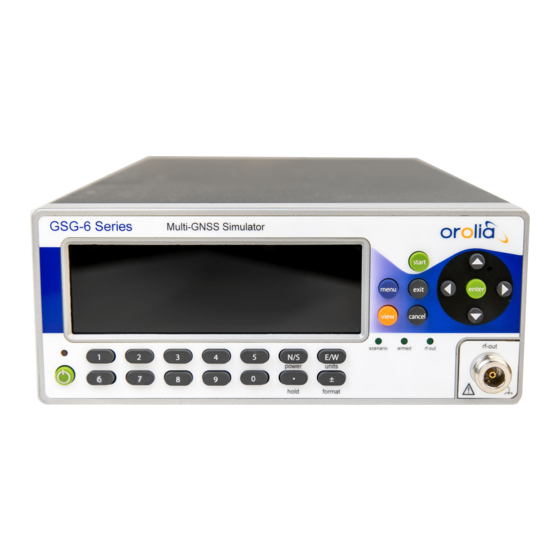
3.1 Front Panel 3.6.3.2 Proxy Configuration 3.6.4 Manage Files 3.6.5 Show System Information 3.6.6 Restore Factory Defaults 3.6.7 Calibration Front Panel All GSG-5/6 simulators have similar front panels. On the right side are the controls used for managing scenario execution and for display navigation . At the bottom are the numeric keys used to input scenario parameters and other configuration. -
Page 44: Description Of Keys
3.1 Front Panel Note: The N-type RF-connector is equipped with a DC block to prevent the flow of direct current up to 7V in order to protect the GSG unit. 3.1.1 Description of Keys 3.1.1.1 Power ON/OFF key is a toggling secondary power switch. Part of the instrument is always ON as long as power is applied, this standby condition is indicated by a red LED above the key. -
Page 45: View
3.1 Front Panel When reviewing/editing configuration settings, press menu to exit the current sub-menu, and return to the main menu, regardless of the current display. You will be asked to save your changes (same as exit When running a scenario, press menu to display the configuration of the scenario currently running. -
Page 46: (Hold)
3.2 Rear Panel In scenario execution, View 2/5 and higher, press +/– (format) to switch between frequency bands (L1, L2 and L5). 3.1.1.13 [.] (hold) Use the "DOT" [.] (hold) key together with numeric keys , where appropriate. During scenario execution, press the [.] (hold) key to hold/resume the simulated movement (trajectory) . -
Page 47: The Gsg Main Menu
3.3 The GSG Main Menu External Reference Input : Can be selected as a reference via the Interface and Reference menu. External Trigger Input : Optional signal input for scenario triggering. GPIB Connector : The address is set in the Interface and Reference menu. Ethernet Connector : Data communications port used with TCP/IP networks. -
Page 48: Start" Menu
3.4 "Start" Menu Transmit RF power (see also: "Adjusting Transmit Power" on page 101) Trajectory shape Scenario Current Position (latitude/longitude) In the upper right-hand corner, abbreviations may be shown: REM : remote commanding EXTREF : external reference clock is selected in the Options menu ARM : the unit is waiting for a trigger to start the scenario HOLD : the movement along the trajectory is paused "Start"... -
Page 49: Scenario Start Variations
3.4 "Start" Menu 3.4.1 Scenario Start Variations Hold before manual start Once you pressed start , or enter (with the Start main menu option highlighted), the GSG unit requires some time to launch the scenario (the delay depends on the size/complexity of the scenario data). -
Page 50: View 1/X
3.4 "Start" Menu Figure 3-5: Views displayed during scenario execution To display the views in successive order, press the view key. In the lower right corner, e.g. View 2/6 may be displayed, indicating the current view/total number of views. The total number, and number of signals used in the scenario content of views depends on the a maximum of 5 in... - Page 51 3.4 "Start" Menu In view : Shows the abbreviation of each satellite system, followed by its number of satellites in view/GSG channels reserved. Satellite system abbreviations are: GP : GPS GL : Glonass GA : Galileo BD : BeiDou IR : IRNSS QZ : QZSS : Pseudo-Range Number (satellite identifier).
- Page 52 3.4 "Start" Menu iUC , for unmodulated BeiDou interference signal iUJ , for unmodulated QZSS interference signal iUx , for unmodulated GLONASS interference signal, where ‘x’ is the frequency slot ranging from -7 to 6 iSg , for sweeping GPS interference iSr , for sweeping Glonass interference iSe , for sweeping Galileo interference iSc , for sweeping BeiDou interference...
-
Page 53: Last View
3.5 "Select" Menu Changing the Transmit Power setting becomes effective immediately, and also impacts noise generation levels (if in use – available with GSG-5, GSG-55, GSG-56 and GSG-62, 63, and 64). E x a m p l e S135 The example above illustrates two GPS signals ( ), one SBAS signal ( ), one multipath signal (... - Page 54 3.5 "Select" Menu Prior to running a scenario, you have to select it from the list of scenarios installed on the GSG unit: In the Main Menu , highlight Select using the arrow keys, then press enter to display the list of scenarios currently loaded: Scroll through the list by using the UP/DOWN keys.
-
Page 55: Start Time
3.5 "Select" Menu "Leap Second" on page 49 "Event Data" on page 50 "Antenna Settings" on page 55 "Advanced Configuration Options" on page 57 "Multipath signals" on page 57 "Interference signals" on page 59 "Base station" on page 62 "Environment models" on page 63 "Atmospheric model"... -
Page 56: Duration
3.5 "Select" Menu NTP real time and downloaded Ephemeris Using NTP as start time in conjunction with Ephemeris set to Download is subject to licensing options, as it requires the Simulate Now option to be present. In this configuration, the GSG unit will simulate the sky as it is in that start position at current time. -
Page 57: Latitude, Longitude, Altitude
3.5 "Select" Menu Looping : The scenario will be replayed infinite times, re-starting every time after its set duration has expired. For this mode, the trajectory should be loop- shaped , i.e. have the same start/end point. Otherwise, an error will likely be thrown once the receiver-under-test upon the first replay is moved from the end point to the start point in an unrealistically short time. -
Page 58: Predefined Trajectories
3.5 "Select" Menu use pre-defined/built in trajectories modify pre-defined/built in trajectories (in GSG, or using the GSG Studioview software) create trajectory files in StudioView, and upload them. Note: If the RSG License Option is installed, you can also control movement in real- time over the protocol. -
Page 59: Trajectory Files
3.5 "Select" Menu Circle : The user is moving in a circle throughout the scenario replay. When Circle is selected, a dialog is shown asking the parameters describing this trajectory. These parameters include diameter [meter], speed [m/s] and direction [clockwise/anticlockwise]. The start position of the trajectories is the position specified in the Configuration View 1/3 , under Latitude, Longitude and Altitude. -
Page 60: Timestamp Usage In Trajectories
NMEA trajectory intact. Therefore, it is not necessary for the scenario start time to match the NMEA time stamp. A given NMEA trajectory can be replayed in any GPS time frame, utilizing any earth coordinates. As of firmware version 3.0, Spectracom GSG units support 10 Hz NMEA data. CHAPTER •... -
Page 61: Ephemeris
3.5 "Select" Menu 3.5.5 Ephemeris The satellite constellations and the transmitted navigation data of each satellite are dynamically built, once you start the scenario or the signal generation. The constellation and the navigation data RINEX data is based on stored in the unit, or uploaded to the unit. The constellation orbits can be SP3 format refined by providing precise orbit information in (for details, see below). -
Page 62: Download Ephemeris
3.5 "Select" Menu the YUMA files will define the almanac and the ephemeris will be derived from the default RINEX data. 3.5.5.2 Download Ephemeris The user can let the unit automatically download navigation data from official websites. The navigation data, files and GLONASS almanac files are retrieved from the same sites as brdc mentioned under "Default Ephemeris"... - Page 63 3.5 "Select" Menu The number of RINEX files necessary depends on the scenario’s start time and duration, and must be equal to the total number of simulation days (including start/end days utilizing less than 24 hours). In the event that dates for the user-specified data do not match the scenario’s start time, then GSG will transform the start time in order to resolve the conflict.
- Page 64 3.5 "Select" Menu The scenario is restricted to start times within this range. If a scenario runs beyond this range of time, no new satellites will be added. If the user specifies a start time outside this range, a dialog will advise the user that the ephemeris and almanac are dates are mismatched.
-
Page 65: Leap Second
These can cause the GSG to generate signals that are deemed ‘bad’ by a receiver and may not be used in a fix or for navigation. This data is not maintained by Spectracom and is not guaranteed. The GPS and QZSS almanac files specified must comply with the YUMA file Note: format and match the first 5 characters exactly for field identification. -
Page 66: Event Data
3.5 "Select" Menu Figure 3-7: Leap second configuration The leap second field can be set to -1, 0 or 1, and indicates a future change in the leap second value. While the Δt is set automatically based on information in the used ephemeris data, the value given in the leap second field will impact values related to LSF (Leap Seconds Future). - Page 67 3.5 "Select" Menu 2. TIME {scenario | prn SATID | channel NUMBER} abspower on|off|ABSPOWER 3. TIME {prn SATID | channel NUMBER} duplicate RELRANGE RELDOPPLER RELPOWER EFFECTIVETIME [CHTARGET] 4. TIME {prn SATID | channel NUMBER} multipath RELRANGE RANGECHANGE RANTEINTERVAL RELDOPPLER DOPPLERCHANGE DOPPLERINTERVAL RELPOWER POWERCHANGE POWERINTERVAL [INSTANCE] 5.
- Page 68 3.5 "Select" Menu Should > length ( ), the ENDBITPOS- STARTBITPOS+1 HEXSTRING HEXSTRING will be used as a repeating pattern to replace the bits between STARTBITPOS ENDBITPOS Multiple navbits events may be applied to the same message. Note that a navbits event is applied to the first message from the event with the TIME...
- Page 69 3.5 "Select" Menu SFID a subframe ID (with GPSL1 and L2P signals) a message type (with L2C and L5 signals) a frame ID (with Glonass) PAGEID a page ID (with GPSL1 and L2P signals) 0 (not relevant) when the subframe ID is 1-3 0 (not relevant) with L2C and L5 signals a string idID (with Glonass).
- Page 70 3.5 "Select" Menu 11.0 prn G9D multipath 25.0 0.01 1.5 0.0 0.0 0 -15.0 0.0 0 12.0 prn G1 navbits L1CA 1 0 77 77 1 0 0 170.0 channel 6 delete 180.0 channel G9D delete 1.0 seconds into the scenario the power level of the satellite in channel 7 will be attenuated by 3.0 dB.
-
Page 71: Antenna Settings
3.5 "Select" Menu Note also that settings of events overrule the Transmit power setting specified abspower under Options > Transmit power , while observing the external attenuation settings. Duplicating a satellite at time 00.00 is not permitted. 3.5.8 Antenna Settings Several antenna- related settings can be configured to allow for optimal scenario simulation: antenna gain pattern, lever arm, and elevation mask. -
Page 72: Lever Arm
3.5 "Select" Menu The first line of the antenna file is expected to define the File Type. The GSG defines phi 0 degrees, i.e. the x-axis of phi, to point towards the north direction. 3.5.8.2 Lever arm A lever arm can be specified to separate the antenna position from the body mass center of the vehicle: All trajectory movements in the simulation will act on the body mass center of the vehicle. -
Page 73: Advanced Configuration Options
3.5 "Select" Menu 3.5.9 Advanced Configuration Options 3.5.9.1 Multipath signals A multipath signal is a GNSS signal bouncing off a reflective surface prior to reaching the GNSS receiver antenna. Quite likely, this causes many of the same signals to arrive at the receiver at different times. - Page 74 3.5 "Select" Menu Satellite This specifies which satellite is to be duplicated by the multipath signal. The value specified is a running number starting from 1 to the number of satellites defined to be in the scenario. ‘1’ would mean that we will duplicate the satellite in the first position when scenario starts. Range Offset : The Range (or: Code) offset in meters.
-
Page 75: Interference Signals
"GSG Series Model Variants and Options" on page 136). Spectracom GSG- Series simulators can generate GNSS interference signals to test GNSS receiver performance. To configure an interference signal, navigate to Select > Select Scenario > Configure Scenario, View 2/3: Advanced: Interference Signals . - Page 76 3.5 "Select" Menu Signal type Any signal type your GSG unit is licensed for can be configured (un- licensed signal types are grayed out). Figure 3-12: Interference signal type configuration view The interference signal type can be: GPS : L1CA, L1P, L2P, L1P(Y), L2P(Y), GPS carrier, SBAS GLONASS : L1, L2 or GLONASS carrier Galileo: E1, E5a, E5b or a Galileo carrier BeiDou : B1,B2 or BeiDou B1,B2 carrier signal...
- Page 77 3.5 "Select" Menu Satellite ID/Frequency slot For GPS, SBAS, Galileo, GLONASS, BeiDou, IRNSS and QZSS signals, the Satellite ID must be specified. For GLONASS carrier signals the Frequency slot must be specified. In some instances, this field is not applicable, and will be grayed out (e.g., GPS carrier). Frequency offset The frequency offset refers to nominal frequency of the selected signal/frequency slot.
-
Page 78: Base Station
3.5 "Select" Menu 3.5.9.3 Base station This feature allows you to configure a Base station , as it is typically used for high- precision positioning, e.g. in surveying applications: A receiver in a fixed and known position tracks the same satellites the mobile receiver ("rover") does, and in real-time transmits corrective positioning data to the receiver in the rover via a radio transmission stream. -
Page 79: Environment Models
GSG can successfully handle vehicle models with up to 130 triangles. Models should be optimized for a low polygon count. The triangle count is limited to a total of 300 for the combined environment and vehicle models. For additional information, see the Spectracom Technical Note Vehicle Modeling CHAPTER •... - Page 80 3.5 "Select" Menu Propagation Environment Models Built-in signal propagation models can be used to simulate multipath propagation in rural, sub- urban and urban areas. Used propagation models are specified in ITU- R Recommendation M.1225, “ Guidelines for evaluation of radio transmission technologies for IMT-2000 ”...
- Page 81 3.5 "Select" Menu The Propagation environment is defined by the environment type (open/rural/sub-urban/ urban) and three parameters: Open sky limit, Obstruction limit and NLOS probability. Default values for the parameters in each environment type are given in the table below. The Open environment type is the default, meaning that all satellites assume free-space propagation.
-
Page 82: Atmospheric Model
3.5 "Select" Menu between switching the environment model should be more than one minute. The Event must be stated without parameters, or alternatively scenario propenv with all three parameters specified. Valid ranges for the parameter values are: : 0.0 to 90.0 (degrees) OPENSKYLIMIT : 0.0 to OPENSKYLIMIT (degrees) OBSTRUCTIONLIMIT... - Page 83 3.5 "Select" Menu Tropo model A number of tropospheric models are supported by the device. These are: Saastamoinen model. The model is based on Saastamoinen, J., 'Atmospheric Correction for the Troposphere and Stratosphere in Radio Ranging of Satellites,' The Use of Artificial Satellites for Geodesy, Geophysics Monograph Series, Vol.
-
Page 84: Satellite Configuration
3.5 "Select" Menu Figure 3-18: Tropospheric delay vs. elevation angle 3.5.10 Satellite Configuration Depending on the model and configuration of your GSG unit, and the scenario chosen, several satellite systems can be simulated in a scenario, each of which you may want to configure in accordance with the requirements for your receiver-under-test. -
Page 85: Satellite Systems
3.5 "Select" Menu Satellite System , e.g., GPS, Glonass (see "Satellite Systems" below) Number of satellites simulated for a given satellite system (see "Number of Satellites" below) Signal Type , e.g., L1, L2 (see "Frequency Bands and Signal De-/Activation" on the next page) Satellite Constellation [GPS: "block"] (see "Satellite Constellations"... -
Page 86: Frequency Bands And Signal De-/Activation
3.5 "Select" Menu The license and GSG model used (number of available channels ) How many frequency bands are used, e.g., if 64 channels are available, 64 GNSS L1 satellite signals can be simulated, or, e.g., 32 L1/L2 satellite signals. (Note that GPS L2 and L2C are using separate channels, as are the Galileo bands E5a and E5b.) The default setting is Auto , i.e. - Page 87 3.5 "Select" Menu P(Y): Pseudo encryption For Glonass: For Galileo: For BeiDou: For QZSS: SAIF De-/Activating Signals Frequency bands can be turned ON/OFF separately, so as to configure which types of RF signals specific to each supported satellite system shall be active/inactive when a scenario is running. Depending on the configuration of your GSG unit, all of the frequency bands listed above can be turned ON/OFF.
-
Page 88: Satellite Constellations
3.5 "Select" Menu simulating a one-band antenna reserving the maximum number of channels for other requirements (e.g., L1-only transmission) Considerations: Altering active RF signals will not alter the navigation message. Hence from a receiver point of view, choosing to de-active L2 and L5 will mimic the situation of using a single band (L1) antenna. - Page 89 3.5 "Select" Menu Note: numbers refer to the individual GPS satellites (Glonass satellites are named Explicitly specify the constellation for each individual satellite, using GSG StudioView: Figure 3-21: GPS Constellation configuration (StudioView) This functionality may be required for the configuration of scenarios taking place in the past, or 'What-if' scenarios.
-
Page 90: Encryption
3.5 "Select" Menu (default) For Glonass: Glonass-K1 Glonass-M (default) 3.5.10.5 Encryption Next to the unencrypted L1 band Coarse/Acquisition Pseudo-Random Noise (C/A PRN code), the Precise (P), but encrypted Pseudo Random Noise code is used to modulate both the L1, and the L2 carriers. -
Page 91: Sbas Satellites
L1/L2 P(Y) signals for codeless applications, or to provide a signal in the band to better emulate the real world. In the GSG-6 series, the NAV message transmitted by the GPS satellites is updated to reflect if (pseudo-) encryption is active or not. This is specified by bit 19 in the second word of subframe one. - Page 92 3.5 "Select" Menu Figure 3-23: GNSS SBAS systems GSG can simulate SBAS satellites. Each scenario defines the number of SBAS satellites that should be simulated. There can be 0, 1, 2, or 3 SBAS satellites per scenario. To review/edit the number of SBAS satellites for the scenario chosen, navigate to: Select > [ Select Scenario ] >...
- Page 93 3.5 "Select" Menu Default SBAS messages (MT63) EGNOS/WAAS message files The default SBAS messages are always available. These messages should be recognized by SBAS-compatible receivers. However, they carry no information and will therefore not enable the receiver to correct GPS signals. SBAS message files for both EGNOS, and WAAS are supported.
-
Page 94: Options" Menu
3.6 "Options" Menu Note: The SBAS corrections are ‘applied backwards’ to the output GPS signals by adjusting the signal ranges. It is also possible to download the EGNOS and WAAS files from the ftp servers, and select them for use in the scenario: The file name holds the information on the applicable time & date, which is NOT available in the content of the file (all time is relative), and must follow these naming conventions: For EGNOS :... - Page 95 3.6 "Options" Menu Caution: To learn more about signal level compliance in the United States, see "Signal Power Level Considerations" on page 22. If you live in other countries, check your local emission standards. The transmit power is specified in dBm . The supported range is: Max.
-
Page 96: External Attenuation
3.6 "Options" Menu Considerations A common problem is that signals too strong or too weak are used. A signal too strong will typically ‘jam’ the receiver, causing it to erroneously find many shadow signals. It is recommended that you familiarize yourself with the typical signal/noise values for real satellites, and try to obtain similar values when using this unit. -
Page 97: Noise Generation
3.6 "Options" Menu 3.6.1.2 Noise Generation GSG-5/6 has the capability to simulate noise on the GPS L1 band. Noise simulation can be a powerful tool for receiver testing, since it allows for a strong signal to be submitted, without jamming the receiver. To access the Transmit Power view, which—among other things—... - Page 98 3.6 "Options" Menu (not SNR) is the figure that the receivers typically display as an indication of quality for the received, digitally modulated signal. If the receiver has bandwidth of 6 MHz, SNR would be: SNR = 44 dB Hz/(6 x 10 Hz) = 44 –...
-
Page 99: Signal Generator
3.6 "Options" Menu setting. In this case, the ambient noise power spectral density limits the achievable carrier- to-noise ratio. The Carrier-to-Noise density will be set to its maximum value, not to the value requested by the user. The noise generator does not generate any additive noise in this situation. -
Page 100: Signal Type
3.6 "Options" Menu Figure 3-26: Signal Generator configuration view (depends on licensing options installed) The following Signal Generator options can be configured: 3.6.2.1 Signal type The Signal type selection will open a new view, as shown below. Note that the view depends on the licensing options installed on your unit. -
Page 101: Satellite Id
Pure Carrier Signal : GSG will transmit an un-modulated signal (pure carrier), using the user-specified signal strength, and frequency offset from the nominal frequency. With GSG-6 series simulators, it is possible to generate carrier signals for L1 and L2 at the same time. -
Page 102: Frequency Offset
3.6 "Options" Menu be further limited so that the maximum difference between the strongest and the weakest signal is never more than 72 dB. The resolution is: 0.1 dBm. Default setting: -125.0 dBm Caution: If you are using an antenna (rather than an RF cable), see "Signal Power Level Considerations"... -
Page 103: Interface And Reference
3.6 "Options" Menu If set to OFF , the signal generation is started by pressing the START key, and stopped by pressing CANCEL . When a signal is generated, the simulated GPS time and the text Transmission ON are displayed (see illustration below). Note that Power and Frequency offset can be edited while the transmission is ON. -
Page 104: Network Configuration
3.6 "Options" Menu 3.6.3.1 Network Configuration To access the Network configuration view, navigate to Options > Interface and Reference > Select Interface Type : Ethernet . Highlight the menu item Network , and press enter ; the Network configuration screen will be displayed: IP Configuration Figure 3-30: Static IP address configuration... -
Page 105: Proxy Configuration
3.6 "Options" Menu In the event that GSG cannot resolve the NTP server address, upon start-up, the error message NTP client unable to set time will be displayed: Confirm the message by pressing enter , and navigate to: Network configuration view, Options > Interface and Reference > Select Interface Type : Ethernet . -
Page 106: Manage Files
3.6 "Options" Menu Figure 3-31: Proxy Configuration view 3.6.4 Manage Files The Manage Files view display allows management of the navigation files, scenario files, trajectory files and event files. To access this view, navigate to Options > Manage Files : Figure 3-32: Manage Files top level view Navigating... - Page 107 3.6 "Options" Menu Copying and renaming files When copying or renaming a file, a keyboard is displayed for entering a new file name. Use the arrow keys and the ENTER key to select letters for the file name. LEFT/RIGHT arrow keys move the cursor.
-
Page 108: Show System Information
3.6 "Options" Menu 3.6.5 Show System Information The System Information view displays information about the GSG model, serial number, firmware version, oscillator type, and installed options (if any). In addition, the amount of free storage space available for scenarios and other user files is shown. To access this view, navigate to Options >... -
Page 109: Calibration
Calibration Recommendations Is recommended that you adhere to the following calibration guidelines : Spectracom recommends calibration every 2 years to ensure the frequency is within specification and the power levels are correct. If you have purchased the optional Ultra-High-Stability OCXO (option 40/54), Spectracom recommends calibration every year for this reference to ensure operation to specifications. - Page 110 3.6 "Options" Menu To carry out a user calibration, highlight Calibrate and press enter . Confirm your choice, and enter the password, in order to make sure the calibration settings are not changed unintentionally. The password is 62951413 (first 8 digits of π backwards). Figure 3-40: Entering the calibration password Note:...
-
Page 111: Frequent Tasks
The list is not complete. Should you miss for a task that should be included this list, please submit your suggestion techpubs@spectracom.orolia.com . Thank you. T he following topics are included in this Chapter: 4.1 Working with Scenarios 4.1.1 Scenario Start/Stop/Hold/Arm 4.1.2 Running a Scenario 4.1.3 Holding a Scenario 4.1.4 Configuring a Scenario 4.2 Locking/Unlocking the Keyboard... -
Page 112: Working With Scenarios
4.1 Working with Scenarios Working with Scenarios The following tasks are frequently performed in the context of scenario execution and configuration: 4.1.1 Scenario Start/Stop/Hold/Arm See under: "Scenario Start Variations" on page 33. 4.1.2 Running a Scenario During scenario execution, you can ... Press view to display up to 6 different views to monitor the execution of your test scenario... -
Page 113: Holding A Scenario
4.1 Working with Scenarios 4.1.3 Holding a Scenario Holding a scenario means to temporarily prevent your GNSS receiver from continuing to move along its scenario trajectory (i.e., halting the trajectory), while the simulation continues to run otherwise (time continues to elapse). This can be done manually, by pressing the [.] / hold key, or by using the SCPI command SCENario:CONTrol , see "SOURce:SCENario:CONTrol"... - Page 114 Environment models can be changed to ‘set’ which allows the selection of Environment SketchUp and Vehicle models (created with the third-party tool (a Spectracom Technical Note about Vehicle Modeling using Sketchup is available upon request). The Atmospheric model submenu. Note: Some of the functionality shown is optional.
- Page 115 4.1 Working with Scenarios Note: Some of the functionality shown is optional and may be grayed out. For more information on GSG Options, see "GSG Series Model Variants and Options" on page 136. For each satellite constellation your GSG unit can simulate (e.g., GPS), you can: In the Satellites View (see illustration below), set the maximum...
-
Page 116: Locking/Unlocking The Keyboard
4.2 Locking/Unlocking the Keyboard Note: For the different options on how to start a scenario, see "Scenario Start Variations" on page Locking/Unlocking the Keyboard The keyboard locking functionality prevents any unwanted modifications from being made. When the keyboard lock is engaged, it is not possible to change parameters, or edit scenario execution via the front panel. -
Page 117: Adjusting Transmit Power
4.3 Adjusting Transmit Power Ensure that the CLI is connected to your GSG unit (see "Using the CLI" on page 103). Enter the following command: write SOURce:KEYLOCK:PASSWord [wxyz] The keyboard lock code can be changed at any time. The user-issued lock code [wxyz] must be 4-8 digits in length, and contain only numerical characters. - Page 118 Example GSG Web UI, showing a logged GPS almanac file STUDIOVIEW : Opens the StudioView web page: www.spectracom.com/Studioview DOCUMENTATION : Opens the GSG Documentation web page: www.spectracom.com/GSG Documentation REGISTRATION : Opens a link to the Product Registration we page: www.spectracom.com/Registration CHAPTER •...
-
Page 119: Using The Cli
4.5 Using the CLI Using the CLI Open the "GSG StudioView Software" on page 135, and then the Command-Line Interpreter (CLI) by clicking the MONITOR icon: Click the Globe icon. The Connections window will open. Click the green PLUS icon in the top-left corner, and enter the name of the new connection, and its IP address (which can be found under the GSG menu Options >... -
Page 120: Updating Firmware
To determine which firmware version is currently installed on your GSG unit, navigate to Options > Show system information . To determine the latest GSG firmware version, and download it to your Personal Computer, Spectracom website see the . (This link also points to firmware update instructions.) - Page 121 4.8 Uploading Files using StudioView National Instruments engine is required, which can be downloaded directly from the website. Once VISA Run-Time and GSG StudioView are installed, open GSG StudioView. From the Application Tips screen, or from the toolbar under Tools , select Uploader . On the Uploader screen, click the button Select devices for uploading : The Connections window will open, displaying all TCP/IP, GPIB and USB connections.
- Page 122 , first ensure that the scenario file (. file) and any scen trajectory, event, or navigation file associated with the scenario are stored in the StudioView repository. By default this location is: C:\Users\username\Documents\Spectracom\GSG StudioView\Repository CHAPTER • User Guide GSG-5/6 Series Rev. 22...
-
Page 123: Leap Second Configuration
4.9 Leap Second Configuration Note: username location may depend on your version of the Windows operating system you’re using. Click the Open Folder button (next to Select file for uploading ), and navigate to the scenario file in the repository. Click the Start button to start the upload. - Page 124 4.9 Leap Second Configuration When the leap second is , then these values are used: set to zero Δt = Δt = WN – 1, and DN = 1 Note that downloaded and default navigation data files do not contain any LSF information (RINEX v2.1).
-
Page 125: Reference
5.13 GSG Series Model Variants and Options 5.13.1 Which GSG Model & Options Do I Have? 5.13.2 GSG Models & Variants 5.13.2.1 GSG-51 Series 5.13.2.2 GSG-5 Series 5.13.2.3 GSG-6 Series 5.13.3 List of Available Options 5.14 Problems? 5.14.1 Technical Support 5.14.1.1 Regional Contact 5.15 License Notices... -
Page 126: The Gsg Web Ui
5.1 The GSG Web UI The GSG Web UI Spectracom GSG Series simulators feature a Web- based user interface (throughout this documentation referred to as " Web UI "), accessible via a standard Web browser (e.g., Mozilla Firefox or Internet Explorer) installed on a computer with access to the same network to which your GSG unit is connected. - Page 127 5.2 Messages Could not initialize the keyboard. A possible hardware issue exists. Please contact service. Could not initialize web interface. A possible firmware issue exists. Re-install firmware. If problem persists, then contact service. Scenario is modified. Do you want to save changes using a different name? Scenario configuration has been modified.
- Page 128 5.2 Messages Configuring the Internet Protocol address failed. Please check your network settings and try again. Cannot save unit parameters. Saving of settings failed. Try restarting the device and saving parameters again. If it still fails, then please contact service. Cannot load unit parameters.
- Page 129 5.2 Messages supported). Please check navigation data. Navigation data is not valid. No ephemeris for this PRN/date. In the signal generator, navigation data is not found for the selected PRN and/or date. Try again with different values. File missing. The navigation data file was missing when starting the signal generator. Select another option in the ephemeris list and try again.
- Page 130 5.2 Messages Cannot delete file. Removing of file fails. Cannot rename file. Renaming a file failed. This condition may occur when there is no free storage space. Try removing any unnecessary files, and rename the file again. Cannot copy file. Copying a file failed.
-
Page 131: Timing Calibration
5.3 Timing Calibration An unexpected problem has occurred while downloading and/or loading SBAS data. Try scenario again. If problem persists, then contact service. Problem opening trajectory file. Please review scenario settings. Restart GSG-5/6. Cannot save scenario configuration. Saving of scenario settings failed. Try restarting the device and saving scenario configuration again. -
Page 132: Nmea Logging
5.4 NMEA Logging GPS_L2 -40.0E-9 [board1] GPS_L1 -60.0E-9 GPS_L2 -60.0E-9 [board2] GPS_L1 -60.0E-9 GPS_L2 -60.0E-9 [board3] GPS_L1 -60.0E-9 GPS_L2 -60.0E-9 NMEA Logging GSG offers the possibility to log a scenario’s execution in NMEA data. Every second a “snapshot” of the user and satellites’ status is taken and recorded in the form of 3 standard NMEA sentence types. -
Page 133: Execution Log
5.5 Execution Log Execution Log During everyday operation, your GSG unit will maintain a log, which is kept in the file . In this log file, the unit stores information about the observations/executionlog.txt scenarios run, and possible errors that may have occurred, which can be helpful with troubleshooting. -
Page 134: Yuma Almanac File
5.7 YUMA Almanac File Observation files supported include GPS, GLONASS, Galileo, BeiDou and mixed. The RINEX file can be used in post-processing with the navigation data obtained from receiver. Saving RINEX Navigation Data It is also possible to log RINEX navigation data for a running scenario. This feature can be enabled using the SCPI command: SOURce:SCENario:NAV <ON|OFF>... -
Page 135: Default Settings
5.8 Default Settings Orbital Inclination(rad): 0.9597571420 Rate of Right Ascen(r/s): -8.1828408482E-09 SQRT(A) (m 1/2): 5153.650309 Right Ascen at Week(rad): 1.2710842193E+00 Argument of Perigee(rad): 1.117132574 Mean Anom(rad): –3.0896651067E+00 Af0(s): 1.7600243882E-04 Af1(s/s): 1.3415046851E-11 week: 755 Default Settings The factory settings are considered default settings. You can restore these settings at any time by navigating to Options >... - Page 136 5.9 Pre-Installed Scenarios output power of these scenarios has to be set by the user ( Options > Transmit power ). More advanced scenarios, events, and trajectories can be found in the StudioView repository. CHAPTER • User Guide GSG-5/6 Series Rev. 22...
-
Page 137: Default Scenario Satellites
5.10 Default Scenario Satellites Table 5-1: Scenarios Model Scenario Position Start Date GPSStatic N043° 04' 01/01/2016 59.257",W077°35'20.674" 14:00 GSG-5/54/55/56/62/63/64 GPSCircle N043° 04' 01/01/2016 OPT-TRAJ 59.257",W077°35'20.674" 14:00 GSG-5/55/56/62/63/64 OPT- GPSStaticSBAS N043° 04' 01/01/2016 SBAS 59.257",W077°35'20.674" 14:00 GSG-53/56/62/63/64 OPT-GLO GPSGLOStatic N60°27'24.41", 01/01/2016 E42°7'24.42"... -
Page 138: Glonass Default Satellite Types
5.10 Default Scenario Satellites 3 x Block IIA satellites 12 x Block IIR satelliets 7 x Block IIR-M satellites 10 x Block IIF satellites GSG uses this constellation as the default for its scenarios. You can, however, change this when developing or manipulating scenarios, e.g., to simulate an event in the past. -
Page 139: Scenario File Format
5.11 Scenario File Format 5.11 Scenario File Format Scenarios are defined by means of text files which contain a set of keywords and values, as described below. Scenario files used with GSG-5/6 units must follow the described format. All fields are optional and will assume default values if not provided. - Page 140 5.11 Scenario File Format INTEGER QZSSSatellites IRNSSSatellites INTEGER Startpos DECIMAL degN DECIMAL degE DECIMAL m DECIMAL degN DECIMAL degE DECIMAL m BaseStationPos FILENAME [0|1] | Static | 3GPP | Circle UserTrajectory LeverArm DECIMAL DECIMAL DECIMAL DeltaLSF -1|0|1 DECIMAL DECIMAL 1|-1 TrajectoryParameters FILENAME | Zero model | Patch | Helix | Cardioid | AntennaModel...
- Page 141 5.11 Scenario File Format 1 | 0 GLOL1 GLOL2 1 | 0 GALE1 1 | 0 1 | 0 GALE5a 1 | 0 GALE5b BDSB1 1 | 0 BDSB2 1 | 0 1 | 0 QZSSL1CA 1 | 0 QZSSL2C 1 | 0 QZSSL5 QZSSL1SAIF...
- Page 142 5.11 Scenario File Format 1 | 0 GALE1 GALE5a 1 | 0 GALE5b 1 | 0 1 | 0 BDSB1 1 | 0 BDSB2 QZSSL1CA 1 | 0mode 0 | 1 | 2 | 3 SatId INTEGER INTEGER Power INTEGER FreqOffset DECIMAL degN DECIMAL degE DECIMAL m | Not set JammerPosition...
- Page 143 5.11 Scenario File Format Scenario File Parameter Value Comment Keyword StartTime Valid date in the format: Start time in the GPS Time time frame. MM/DD/YYYY Note that seconds must be set to zero. HH:MM:00 When scenario ephemeris data is set to Download, Source then StartTime must be in the past (typically with a Valid range limited to:...
- Page 144 5.11 Scenario File Format Scenario File Parameter Value Comment Keyword BeiDouSatellites [-1, 37] Default: 0 Keyword -1 i mplies 'Auto' – maximum number of Satellites in view will be simulated. QZSSSatellites [-1, 4] Default: 0 Keyword -1 i mplies 'Auto' – maximum number of Satellites in view will be simulated.
- Page 145 5.11 Scenario File Format Scenario File Parameter Value Comment Keyword IonoModel Keyword of comma- Default: On separated filenames Available keywords: [Off, On] 'Off' = 'Off' ( in Graphical user interfaces) 'On' ='Klobuchar' ( in Graphical user interfaces) Tropo Model {'Saastamoinen' ...
- Page 146 5.11 Scenario File Format Scenario File Parameter Value Comment Keyword {'SvBlockII', Example: A space delimited list of Satellite ID specifying 'SvBlockIIA', DefaultGpsSv what satellites are mapped to a non-default 'SvBlockIIR', SvBlockIIR satellite series. 'SvBlockIIR-M', SvBlockIIA G10 G14 For GPS the Satellite ID is built up by the letter 'G' 'SvBlockIIF', SvBlockIIR-M G17 followed by PRN number, e.g.
- Page 147 5.11 Scenario File Format Scenario File Parameter Value Comment Keyword GALE5b [0, 1] , where 0 Default: 1 ('On') corresponds to 'Off' , and 1 to 'On' BDSB1 [0, 1] , where 0 Default: 1 ('On') corresponds to 'Off' , and 1 to 'On' BDSB2 [0, 1] , where 0...
- Page 148 5.11 Scenario File Format Scenario File Parameter Value Comment Keyword rangeInterval [0, 600] Specifying range change interval in seconds with one decimal accuracy. Default: 0 dopplerOffset [-99.99, 99.99] Specifying Doppler offset in meters/seconds. Default: 0 dopplerChange [-99.99, 99.99] Specifying Doppler offset change in meters/seconds / dopplerInterval.
- Page 149 5.11 Scenario File Format Scenario File Parameter Value Comment Keyword GLOL1 [0, 1] , where 0 Specifies the type of signal interference corresponds to 'Off' , and 1 to 'On' GLOL2 [0, 1] , where 0 Specifies the type of signal interference corresponds to ...
- Page 150 5.11 Scenario File Format Scenario File Parameter Value Comment Keyword SatId GPS: [1,32] Specifies the satellite ID (PRN / frequency slot) for GPS carrier: 0 interference signal Glonass: [1, 24] Default: 3 Glonass carrier: [-7,6] For 'Glonass carrier', the term 'SatId' r efers to the Galileo: [1, 36] frequency slot.
-
Page 151: Gsg Studioview Software
GSG StudioView ™ offers a convenient way to create, edit and back-up complex scenarios for a Spectracom GSG series multi-channel GPS/GNSS simulator. While you can manage scenarios in your GSG unit – without the need of an external computer – the ®... -
Page 152: Gsg Series Model Variants And Options
5.13 GSG Series Model Variants and Options 5.13 GSG Series Model Variants and Options Spectracom GSG Series GNSS constellation simulators and signal generators are available in several different Model configurations, and with numerous Option packages, in order to allow for application-specific customization:... -
Page 153: Gsg Models & Variants
Upgrade to 4-channel unit 5.13.2.2 GSG-5 Series Base unit : 4 channels, GPS L1 C/A Options for GSG-5: Upgrade to 8, or 16-channels Upgradable to GSG-6 Series Advanced Feature Set included: SBAS Trajectories Multipath White Noise Programmable PPS (1, 10, 100, 1000) -
Page 154: Series
5.13 GSG Series Model Variants and Options 5.13.2.3 GSG-6 Series Multi-frequency, Multi-system GNSS constellation simulators: Up to 64 Channels and 4 simultaneous frequencies GPS L1 C/A Includes Advanced Feature Set of GSG-5 GSG-6 Model variants: -62 : 32 channels and 2 freq bands... -
Page 155: Problems
Phone support is available during regular office hours under the telephone numbers listed below. 5.14.1.1 Regional Contact Spectracom operates globally and has offices in several locations around the world. Our main offices are listed below: CHAPTER • User Guide GSG-5/6 Series Rev. 22... -
Page 156: License Notices
Some parts of this product use free software released under the terms of the GNU Lesser General Public License, version 3, as published by the Free Software Foundation. Upon request Spectracom will give out source code in accordance with applicable licenses. For contact spectracom.com... - Page 157 5.15 License Notices 1. Exception to Section 3 of the GNU GPL. You may convey a covered work under sections 3 and 4 of this License without being bound by section 3 of the GNU GPL. 2. Conveying Modified Versions. If you modify a copy of the Library, and, in your modifications, a facility refers to a function or data to be supplied by an Application that uses the facility (other than as an argument passed when the facility is invoked), then you may convey a copy of the modified version:...
- Page 158 5.15 License Notices Use a suitable shared library mechanism for linking with the Library. A suitable mechanism is one that (a) uses at run time a copy of the Library already present on the user's computer system, and (b) will operate properly with a modified version of the Library that is interface-compatible with the Linked Version.
- Page 159 5.15 License Notices The licenses for most software and other practical works are designed to take away your freedom to share and change the works. By contrast, the GNU General Public License is intended to guarantee your freedom to share and change all versions of a program--to make sure it remains free software for all its users.
- Page 160 5.15 License Notices "Copyright" also means copyright- like laws that apply to other kinds of works, such as semiconductor masks. "The Program" refers to any copyrightable work licensed under this License. Each licensee is addressed as "you". "Licensees" and "recipients" may be individuals or organizations. To "modify"...
- Page 161 5.15 License Notices as by intimate data communication or control flow between those subprograms and other parts of the work. The Corresponding Source need not include anything that users can regenerate automatically from other parts of the Corresponding Source. The Corresponding Source for a work in source code form is that same work. 2.
- Page 162 5.15 License Notices You may convey a work based on the Program, or the modifications to produce it from the Program, in the form of source code under the terms of section 4, provided that you also meet all of these conditions: The work must carry prominent notices stating that you modified it, and giving a relevant date.
- Page 163 5.15 License Notices Convey the object code by offering access from a designated place (gratis or for a charge), and offer equivalent access to the Corresponding Source in the same way through the same place at no further charge. You need not require recipients to copy the Corresponding Source along with the object code.
- Page 164 5.15 License Notices 7. Additional Terms. "Additional permissions" are terms that supplement the terms of this License by making exceptions from one or more of its conditions. Additional permissions that are applicable to the entire Program shall be treated as though they were included in this License, to the extent that they are valid under applicable law.
- Page 165 5.15 License Notices 8. Termination. You may not propagate or modify a covered work except as expressly provided under this License. Any attempt otherwise to propagate or modify it is void, and will automatically terminate your rights under this License (including any patent licenses granted under the third paragraph of section 11). However, if you cease all violation of this License, then your license from a particular copyright holder is reinstated (a) provisionally, unless and until the copyright holder explicitly and finally terminates your license, and (b) permanently, if the copyright holder fails to notify you of the...
- Page 166 5.15 License Notices work on which the Program is based. The work thus licensed is called the contributor's "contributor version". A contributor's "essential patent claims" are all patent claims owned or controlled by the contributor, whether already acquired or hereafter acquired, that would be infringed by some manner, permitted by this License, of making, using, or selling its contributor version, but do not include claims that would be infringed only as a consequence of further modification of the contributor version.
- Page 167 5.15 License Notices If conditions are imposed on you (whether by court order, agreement or otherwise) that contradict the conditions of this License, they do not excuse you from the conditions of this License. If you cannot convey a covered work so as to satisfy simultaneously your obligations under this License and any other pertinent obligations, then as a consequence you may not convey it at all.
- Page 168 License, or any later version. Copyright 2004, The University of Texas at Austin. Some parts of this product use free software released under the terms of MIT/X11 License. Upon request Spectracom will give out source code according to applicable licenses. Contact spectracom.com information can be found at web address: This license applies to GeographicLib, versions 1.12 and later.
-
Page 169: Scpi Guide
SCPI Guide SCPI Guide comprises a list of all the GSG SCPI commands. T he following topics are included in this Chapter: 6.1 SCPI Guide: Introduction 6.2 Protocol 6.2.1 General Format of Commands 6.2.2 Protocol Errors 6.3 Command Reference 6.3.1 Common Commands 6.3.1.1 *CLS 6.3.1.2 *ESE 6.3.1.3 *ESR? - Page 170 6.3.3.5 SOURce:PPSOUTput 6.3.3.6 SOURce:PPSOUTput? 6.3.3.7 SOURce:EXTATT 6.3.3.8 SOURce:EXTATT? 6.3.3.9 SOURce:NOISE:CONTRol 6.3.3.10 SOURce:NOISE:CONTRol? 6.3.3.11 SOURce:NOISE:CNO 6.3.3.12 SOURce:NOISE:CNO? 6.3.3.13 SOURce:NOISE:BW 6.3.3.14 SOURce:NOISE:BW? 6.3.3.15 SOURce:NOISE:OFFSET 6.3.3.16 SOURce:NOISE:OFFSET? 6.3.3.17 SOURce:ONECHN:CONTrol 6.3.3.18 SOURce:ONECHN:CONTrol? 6.3.3.19 SOURce:ONECHN:SATid 6.3.3.20 SOURce:ONECHN:SATid? 6.3.3.21 SOURce:ONECHN:STARTtime 6.3.3.22 SOURce:ONECHN:STARTtime? 6.3.3.23 SOURce:ONECHN:EPHemeris 6.3.3.24 SOURce:ONECHN:EPHemeris? 6.3.3.25 SOURce:ONECHN:FREQuency 6.3.3.26 SOURce:ONECHN:FREQuency? 6.3.3.27 SOURce:ONECHN:SIGNALtype...
- Page 171 6.3.3.47 SOURce:SCENario:POWer[n]? 6.3.3.48 SOURce:SCENario:POWer 6.3.3.49 SOURce:SCENario:POWer? 6.3.3.50 SOURce:SCENario:FREQBAND:POWer 6.3.3.51 SOURce:SCENario:SVmodel[n]? 6.3.3.52 SOURce:SCENario:SVmodel? 6.3.3.53 SOURce:SCENario:LIST? 6.3.3.54 SOURce:SCENario:ANTennamodel 6.3.3.55 SOURce:SCENario:ANTennamodel? 6.3.3.56 SOURce:SCENario:TROPOmodel 6.3.3.57 SOURce:SCENario:TROPOmodel? 6.3.3.58 SOURce:SCENario:IONOmodel 6.3.3.59 SOURce:SCENario:IONOmodel? 6.3.3.60 SOURce:SCENario:KEEPALTitude 6.3.3.61 SOURce:SCENario: KEEPALTitude? 6.3.3.62 SOURce:SCENario:POSition 6.3.3.63 SOURce:SCENario:POSition? 6.3.3.64 SOURce:SCENario:ECEFPOSition 6.3.3.65 SOURce:SCENario:ECEFPOSition? 6.3.3.66 SOURce:SCENario:DATEtime 6.3.3.67 SOURce:SCENario:DATEtime? 6.3.3.68 SOURce:SCENario:RTCM? 6.3.3.69 SOURce:SCENario:RTCMCFG?
- Page 172 6.3.4.1 MMEMory:CATalog? 6.3.4.2 MMEMory:CDIRectory 6.3.4.3 MMEMory:CDIRectory? 6.3.4.4 MMEMory:DATA? 6.3.4.5 MMEMory:DELete 6.3.4.6 MMEMory:COPY 6.3.4.7 MMEMory:MOVE 6.3.5 Network Subsystem Commands 6.3.5.1 NETwork:MACaddress? 6.3.6 STATus: Subsystem Commands 6.3.6.1 STATus:OPERation:CONDition? 6.3.6.2 STATus:OPERation:ENABle 6.3.6.3 STATus:OPERation[:event]? 6.3.6.4 STATus:QUEStionable:CONDition? 6.3.6.5 STATus:QUEStionable:ENABle 6.3.6.6 STATus:QUEStionable[:EVENt]? 6.3.6.7 STATus:PRESet 6.4 Sensors Command Reference 6.4.1 Supported Sensor Types 6.4.1.1 Accelerometer 6.4.1.2 Linear Accelerometer...
- Page 173 6.5.3.5 SOURce:SCENario:SPEed TIME 6.5.3.6 SOURce:SCENario:SPEed? 6.5.3.7 SOURce:SCENario:HEADing TIME 6.5.3.8 SOURce:SCENario:HEADing? 6.5.3.9 SOURce:SCENario:RATEHEading TIME 6.5.3.10 SOURce:SCENario:RATEHEading? 6.5.3.11 SOURce:SCENario:TURNRATE TIME 6.5.3.12 SOURce:SCENario:TURNRATE? 6.5.3.13 SOURce:SCENario:TURNRADIUS TIME 6.5.3.14 SOURce:SCENario:TURNRADIUS? 6.5.3.15 SOURce:SCENario:VELocity TIME 6.5.3.16 SOURce:SCENario:VELocity? 6.5.3.17 SOURce:SCENario:VSPEed TIME 6.5.3.18 SOURce:SCENario:VSPEed? 6.5.3.19 SOURce:SCENario:ENUVELocity TIME 6.5.3.20 SOURce:SCENario:ENUVELocity? 6.5.3.21 SOURce:SCENario:ECEFVELocity 6.5.3.22 SOURce:SCENario:ECEFVELocity? 6.5.3.23 SOURce:SCENario:ACCeleration TIME...
-
Page 174: Scpi Guide: Introduction
6.1 SCPI Guide: Introduction 6.5.3.47 SOURce:SCENario:PRANge? 6.5.3.48 SOURce:SCENario:CHINview? 6.5.3.49 SOURce:SCENario:SVINview? 6.5.3.50 SOURce:SCENario:SVPos[n]? 6.5.3.51 SOURce:SCENario:SVPos[n]? 6.6 RSG Programming 6.6.1 Usage Recommendations 6.6.1.1 Communication Interface 6.6.1.2 Synchronization 6.6.1.3 Underflow and Overflow 6.6.1.4 Best Practices 6.6.1.5 Limitations 6.6.2 Trajectory FILE Format 6.7 Revision History, SCPI Guide SCPI Guide: Introduction Th SCPI Guide describes the data exchange between a GSG unit, and a PC. -
Page 175: Protocol Errors
6.2 Protocol response to query. When using, for example, telnet client to control the unit, it MMEMory:DATA? is enough just type commands and press enter to send the command. 6.2.2 Protocol Errors Below is a list of possible errors and their explanations. They can be retrieved using tSYSTem:ERRor[:NEXT]? -100,"Command error"... - Page 176 6.2 Protocol -161,"Invalid block data" . A block data element was expected, but was invalid for some reason (see IEEE-488.2, 7.7.6.2); for example, an END message was received before the length was satisfied. -190,"Execution in progress" . Command not allowed in current state. -191,"Execution not in progress"...
-
Page 177: Command Reference
6.3 Command Reference Command Reference 6.3.1 Common Commands 6.3.1.1 *CLS Clear Status Command common command clears the status data structures by clearing all event registers and *CLS the error queue. Also possible executing of scenario or signal generator is stopped. It does not clear enable registers and transition filters. -
Page 178: Esr
<Manufacturer>, <Model>, <Serial Number>, <Firmware Level>, <Options>. Example SEND: *IDN? READ: SPECTRACOM,GSG-5,163049,V6.0.3,16 SBAS TRAJ TRG FN NOW INTF MP PPS RSG RP Options The first option listed is the maximum number of channels the unit has been licensed for. SBAS – Satellite Based Augmentation System satellites TRAJ –... -
Page 179: Opc
6.3 Command Reference TRG – External Trigger FN – Fixed bandwidth noise VN – Variable Bandwidth Noise (GSG-55 only) INTF – Interference channels MP – Multipath NOW – Simulate Now PPS – PPS output (1/10/100/1000) HV – High Velocity/Altitude, Extended Limits Option L2 –... -
Page 180: Opc
6.3 Command Reference SEND: *ESE 1 Start scenario. *OPC will set the operation complete bit in the status register when the start of scenario is done and it is running. SEND: SOURce:SCENario:CONTrol start;*OPC Wait 5s for the scenario to start. Then read the event status register. SEND: *ESR? Check the Operation complete bit (0) in the result. -
Page 181: Rst
6.3 Command Reference 6.3.1.7 *RST Reset Resets the device. Any ongoing activity is stopped and the device is prepared to start new operations. Example *RST 6.3.1.8 *SRE Service Request Enable Sets the service request enable register bits. This enable register contains a mask value for the bits to be enabled in the status byte register. -
Page 182: Sre
6.3 Command Reference Example *SRE 1 In this example, the device generates a service request when a message is available in the output queue. 6.3.1.9 *SRE? Service Request Enable Query Read the value of the service request enable register. Returned format <Integer>... -
Page 183: Tst
6.3 Command Reference Status byte Register (1 = true) Weight Name Condition Enabled operation status has occurred. Reason for requesting service. Enabled status event condition has occurred An output message is ready The quality of the output signal is questionable Error available Not used Not used... -
Page 184: System: Subsystem Commands
6.3 Command Reference RSG Example SEND: *WAI? SEND: SOURce:SCENario:VELocity 123.400,27.25, 210.8000 SEND: SOURce:SCENario:PRYRate 123.400,-2.0000,2.0000,1.0000 Wait until the next 100 msec interval and issue the following commands. 6.3.2 SYSTem: Subsystem Commands 6.3.2.1 SYSTem:ERRor? Function This SYSTem command queries the error queue for an ASCII text description of the next error and removes it from the queue. -
Page 185: System:reset:factory
6.3 Command Reference Note commands are only available during scenario execution. If scenario is SOURce:SCENario not running these error codes are to be returned (for both set and get functions); -191 ,"Execution not in progress". Returned format <error number>,"<Error Description String>" Where: <Error Description String>... -
Page 186: Source:power
6.3 Command Reference 6.3.3.1 SOURce:POWer Function Sets the transmit power of the device. During scenario execution all signals on all bands will get the new transmit power, and all possible power offsets between different satellite constellations and frequency bands are discarded. Command Syntax SOURce:POWer <decimal>... -
Page 187: Source:extref
6.3 Command Reference 6.3.3.3 SOURce:EXTREF Function Specifies the reference clock source. If set to ON, the external reference clock signal is required and used when scenarios are executed, or the signal generator is running. Command Syntax SOURce:EXTREF <ON|OFF> Parameter enum = {ON, OFF} Example SEND: SOURce:EXTREF ON... -
Page 188: Source:ppsoutput
6.3 Command Reference Note This feature is not available on GSG-52. Parameter value = 1, 10, 100, 1000 pulses per second Example SEND: SOURce:PPSOUTput 10 6.3.3.6 SOURce:PPSOUTput? Function Get the current PPS output setting. Command Syntax SOURce:PPSOUTput? Note This feature is not available on GSG-52. Example SEND: SOURce:PPSOUT? -
Page 189: Source:extatt
6.3 Command Reference If the value is inside allowed limits, but other RF parameters need to be modified, they are modified and an error about settings conflict is set. Parameter decimal = [0,30] in dB Example SEND: SOURce:EXTATT 12.2 6.3.3.8 SOURce:EXTATT? Function Query the current external attenuation setting of the unit. -
Page 190: Source:noise:control
6.3 Command Reference Example SEND: SOURce:NOISE:CONTRol ON 6.3.3.10 SOURce:NOISE:CONTRol? Function Get the noise simulation state. Command Syntax SOURce:NOISE:CONTRol? Example SEND: SOURce:NOISE:CONTRol? READ: 6.3.3.11 SOURce:NOISE:CNO Function Set the maximum carrier-to-noise density of the simulated signals. Command Syntax SOURce:NOISE:CNO <decimal> Note Setting not stored during scenario or 1-channel mode execution. The actual C/N of individual signals may be lower than this setting due to various reasons (distance, elevation, modified by event, etc). -
Page 191: Source:noise:cno
6.3 Command Reference 6.3.3.12 SOURce:NOISE:CNO? Function Get the current maximum carrier-to-noise density of the simulated signals. Command Syntax SOURce:NOISE:CNO? Example SEND: SOURce:NOISE:CNO? READ: 39.2 6.3.3.13 SOURce:NOISE:BW Function Set the noise simulation bandwidth. This command is only available with GSG-55 units. Command Syntax SOURce:NOISE:BW <decimal>... -
Page 192: Source:noise:offset
6.3 Command Reference Command Syntax SOURce:NOISE:BW? Example SEND: SOURce:NOISE:BW? READ: 20.2 6.3.3.15 SOURce:NOISE:OFFSET Function Set the frequency offset of the simulated noise from the GPS L1 center frequency (1.57542 GHz). For example, if the noise bandwidth is set to be 20 MHz, and offset is 10 MHz, the noise will be simulated on frequency band 1575.42 …... -
Page 193: Source:onechn:control
6.3 Command Reference Example SEND: SOURce:NOISE:OFFSET READ: -8.2 6.3.3.17 SOURce:ONECHN:CONTrol Function Control the execution of the Signal Generator. Command Syntax SOURce:ONECHN:CONTrol <START|STOP|ARM> Parameter enum {START,STOP,ARM} Example SEND: SOURce:ONECHN:CONTrol start 6.3.3.18 SOURce:ONECHN:CONTrol? Function Query the current state of the Signal Generator. Meaning of returned values is the following: START : Signal Generator is started and running STOP : Signal Generator is stopped and thus not running WAIT : Signal Generator delays startup for 2 minutes to allow the simulation to load required... -
Page 194: Source:onechn:satid
6.3 Command Reference Returned values START, STOP, WAIT, ARMED or ARMING Example SEND: SOURce:ONECHN:CONTrol? READ: START 6.3.3.19 SOURce:ONECHN:SATid Function Set & store (when offline) 1-channel mode satellite identifier. Parameters can be: ‘G’ (or ‘g’) for GPS ‘R’ (or ‘r’) for GLONASS ‘E’... -
Page 195: Source:onechn:satid
6.3 Command Reference Command Syntax SOURce:ONECHN:SATid <letter><integer> Parameter letter [G, R, E, C, J, I, S, , PG, PR, PE, PC, PJ, PI, UG, UR, UE, UC, UJ, UI] decimal [-7-210] Example SEND: SOURce:ONECHN:SATid G11 SEND: SOURce:ONECHN:SATid UR-5 6.3.3.20 SOURce:ONECHN:SATid? Function Query 1-channel mode satellite identifier. -
Page 196: Source:onechn:starttime
6.3 Command Reference Notes If several signal types are selected with either or via SOURce:ONECHN:SIGNALtype menus, then the returned value may have several satellite identifiers separated by comma. If the transmission of data message is disabled, the satellite identifier is preceded by the letter “P”. For example, the identifier is “PG30”... -
Page 197: Source:onechn:starttime
6.3 Command Reference 6.3.3.22 SOURce:ONECHN:STARTtime? Function Query 1-channel mode start time. Command Syntax SOURce:ONECHN:STARTtime? Example SEND: SOURce:ONECHN:STARTtime? READ: 23/11/2010 12:45 6.3.3.23 SOURce:ONECHN:EPHemeris Function Set & store (when offline) 1-channel mode ephemeris files to be used. Ephemeris files may include RINEX v2 or newer navigation message files for GPS and/or GLONASS, “agl” type GLONASS almanac, or EGNOS/WAAS SBAS message files. -
Page 198: Source:onechn:frequency
6.3 Command Reference Command Syntax SOURce:ONECHN:EPHemeris? Example SEND: SOURce:ONECHN:EPHemeris? READ: Default 6.3.3.25 SOURce:ONECHN:FREQuency Function Set & store (when offline) 1-channel mode frequency offset. Parameter can also have optional suffix (MHz, KHz or Hz). Command Syntax SOURce:ONECHN:FREQuency <decimal> Parameter decimal [-6000000, 6000000] in Hz Example SEND: SOURce:ONECHN:FREQuency -54... -
Page 199: Source:onechn:signaltype
6.3 Command Reference SOURce:ONECHN:FREQuency? READ: 4.345 6.3.3.27 SOURce:ONECHN:SIGNALtype Function Sets (when offline) signal(s) to be simulated. Signal type consists of comma separated list of signal names, as described under “Parameters” below. Command Syntax SOURce:ONECHN:SIGNALtype <string> Note Satellite system GPS/GLONASS/GALILEO, BeiDou/QZSS/IRNSS and modulation are set with command. -
Page 200: Source:scenario:load
6.3 Command Reference Command Syntax SOURce:ONECHN:SIGNALtype? Example SEND: SOURce:ONECHN:SIGNALtype? READ: GPS L1CA,GPSL2P SEND: SOURce:ONECHN:SIGNALtype? READ: GPS L1CA,GLOL1,GALE1, BDSB1,QZSSL1CA, IRNSSL5 6.3.3.29 SOURce:SCENario:LOAD Function Load the scenario as specified by <string>. Command Syntax SOURce:SCENario:LOAD <string> Note Calling the command will stop any running scenarios. Parameter String identifier of filename Example... -
Page 201: Source:scenario:control
6.3 Command Reference Command Syntax SOURce:SCENario:LOAD? Example SEND: SOURce:SCENario:LOAD? READ: scen01 6.3.3.31 SOURce:SCENario:CONTrol Function Control the execution of the scenario. Command Syntax SOURce:SCENario:CONTrol <START|STOP|HOLD|ARM> Notes The scenario must be loaded beforehand using SOURce:SCENario:LOAD Calling a START command will first automatically stop any running scenarios. HOLD can be used to pause and resume trajectory movement, not the entire scenario. -
Page 202: Source:scenario:propenv
6.3 Command Reference HOLD : scenario is running, but the trajectory is on hold WAIT : scenario delays startup for 2 minutes to allow the simulation to load required data. The start time derived from the NTP server is then aligned to the next full GPS minute. ARMED : scenario is armed, all data loading is done, but scenario is not yet running but waiting for the trigger to start it ARMING : scenario is being loaded to memory after which it is in ARMED state... -
Page 203: Source:scenario:propenv
6.3 Command Reference Decimal [0.0,1.0] : probability for a satellite with elevation between sky_ nlos_probability limit and obstruction_limit to be non-line-of-sight. Examples SEND: SOURce:SCENario:PROPenv urban SEND: SOURce:SCENario:PROPenv suburban,50,30,0.2 6.3.3.34 SOURce:SCENario:PROPenv? Function Query the current propagation model and its parameters. Command Syntax SOURce:SCENario:PROPenv? Example SEND:... -
Page 204: Source:scenario:observation
6.3 Command Reference $GPGGA,181810.000,6000.1041,N,2400.0553,E,1,15,0.6,587.0,M,0.0- ,M,,,*0F $GPGSV,4,1,15,23,77.7,192.3,44,20,52.8,132.7,44,32,31.2,117.3,- 44,31,24.6,44.0,44*00 $GPGSV,4,2,15,16,9.2,96.3,44,7,1.1,190.7,44,17,0.5,242.4,44,2,- 17.4,319.9,44*00 $GPGSV,4,3,15,30,6.3,1.2,44,4,46.0,280.1,44,13,51.5,230.8,44,2- 5,19.6,184.5,44*2A $GPGSV,4,4,15,126,22.0,178.8,44,124,21.9,182.9,44,120,14.3,223- .6,44*E4 6.3.3.36 SOURce:SCENario:OBServation Function Turn on scenario observations. All parameters are seconds. Start is the number of seconds from scenario start. Duration is length of observations from start. Interval is the interval between the individual observations in the resulting Rinex OBS file. -
Page 205: Source:scenario:observation
6.3 Command Reference 6.3.3.37 SOURce:SCENario:OBServation? Function Query scenario observation parameters. Command Syntax SOURce:SCENario:OBServation? Example SEND: SOURce:SCENario:OBS? READ: 10,3600,1 6.3.3.38 SOURce:SCENario:NAV Function Turn ON/OFF RINEX navigation data logging. The generated files are in RINEX 3.0.2 mixed format, so the information for all the simulated constellations/satellites will be written into one file. -
Page 206: Source:scenario:nav
6.3 Command Reference 6.3.3.39 SOURce:SCENario:NAV? Function Query status of RINEX navigation data logging. Command Syntax SOURce:SCENario:NAV? Example SEND: SOURce:SCENario:NAV? READ: 6.3.3.40 SOURce:SCENario:SATid[n]? Function Query the current satellite identifier of channel n. The parameter n can be 1-5 for GSG-52/53, 1-8 for GSG-54, 1-16 for GSG-55/GSG-56 and 1-32/48/64 for GSG-62/63/64. -
Page 207: Source:scenario:signaltype[N]
6.3 Command Reference Command Syntax SOURce:SCENario:SATid[n]? Note Only available during scenario execution. Example SEND: SOURce:SCENario:SATid5? READ: 123.4,R23 6.3.3.41 SOURce:SCENario:SIGNALtype[n]? Function Query signal type of satellite. The parameter can be: 1-5 for GSG-52/53 1-8 for GSG-54 1-16 for GSG-55/GSG-56 and 1-32/48/64 for GSG-62/63/64. The signal type consists of a comma-separated list of frequency bands and codes (CA or P code) for GPS and frequency bands for GLONASS, Galileo, BeiDou, QZSS and IRNSS. -
Page 208: Source:scenario:signaltype
6.3 Command Reference 6.3.3.42 SOURce:SCENario:SIGNALtype? Function Query signal type of satellite. Signal type consists of comma separated list of frequency bands and codes (CA or P code) for GPS and frequency bands for GLONASS, Galileo, BeiDou, QZSS and IRNSS. Command Syntax SOURce:SCENario:SIGNALtype? <satID>... - Page 209 6.3 Command Reference Parameter satID – GPS, Glonass, BeiDou, QZSS and SBAS are supported, the format is explained under "SOURce:ONECHN:SATid?" on page 179. sigtype – One of the signal types supported by the satellite, allowed values are: For GPS : L1CA, GPSL1CA, L1P, GPSL1P, L1PY, GPSL1PY, L1CAP, GPSL1CAP, L1CAPY, GPSL1CAPY, L2P, GPSL2P, L2PY, GPSL2PY, L2C, GPSL2C, L5, GPSL5 Note: The signal types from the same group below share the same...
- Page 210 6.3 Command Reference pageid – For GPS L1 and L2P signals: page id and 0 (not relevant) when subframe id is 1-3 For GPS L2C and L5 signals: 0 (not relevant) For Glonass: string id For Galileo E1 and E5b signals: 0/1 (even/odd) For Galileo E5a: 0 (not relevant) For BeiDou: page id For QZSS L1CA: page id and 0 (not relevant) when subframe id is 1-3...
-
Page 211: Source:scenario:frequency[N]
6.3 Command Reference sour:scen:navbits IMM,J3,L1SAIF,0,2,16,119,FF,0,1 6.3.3.44 SOURce:SCENario:FREQuency[n]? Function Query the current frequency setting ofn when scenario is running. The parameter n can be 1-8 for GSG-54, 1-16 for GSG-55/56 and 1-32/48/64 for GSG-62/63/64. The frequency is returned with a leading timestamp. Command Syntax SOURce:SCENario:FREQuency[n]? Note... -
Page 212: Source:scenario:power[N]
6.3 Command Reference READ: 123.4,-480.513 6.3.3.46 SOURce:SCENario:POWer[n] Function Set the power of channel n when scenario is running. The parameter n can be: 1-5 for GSG-52/53 1-8 for GSG-54 1-16 for GSG-55/56 1-32/48/64 for GSG-62/63/64. The freqband parameter is optional and can be used when only a certain satellite frequency band power is changed. -
Page 213: Source:scenario:power
6.3 Command Reference The parameter n can be: 1-5 for GSG-52/53 1-8 for GSG-54 1-16 for GSG-55/56 1-32/48/64 for GSG-62/63/64. The power is returned with a leading timestamp. Freqband is an optional parameter used to specify for which frequency band the power is returned. -
Page 214: Source:scenario:power
6.3 Command Reference Command Syntax SOURce:SCENario:POWer <satID>,<decimal>[,<freqband>] Note Only available during scenario execution. Parameter Decimal [-160.0,-65.0] dBm, if freqband is not ALL. For ALL, the limits are [-100,100] dB. For a list of satID satellite identifier, see "SOURce:ONECHN:SATid?" on page 179. FreqBand [L1, L2, L5, ALL] Examples SEND:... -
Page 215: Source:scenario:freqband:power
6.3 Command Reference 123.4,-119.7 SEND: SOURce:SCENario:POWer? R22 READ: 124.4,-121.2 6.3.3.50 SOURce:SCENario:FREQBAND:POWer Function Set the power for a frequency band (all satellites) when scenario is running. Freqband is used to specify the frequency band. The freqband value ALL means that the power for all bands is adjusted by the amount indicated. -
Page 216: Source:scenario:svmodel
6.3 Command Reference 1-16 for GSG-55/GSG-56 1-32 for GSG-62. The Space Vehicle model can be: Block II, Block IIA, Block IIR, Block IIR-M, Block IIF or Block IIIA for GPS Glonass-M or Glonass-K1 for GLONASS Command Syntax SOURce:SCENario:SVmodel[n]? Example SEND: SOURce:SCENario:SVmodel4? READ: Block IIR-M... -
Page 217: Source:scenario:list
6.3 Command Reference 6.3.3.53 SOURce:SCENario:LIST? Function List possible models which can be used in the scenarios. Note that for ionomodels, the options are limited to ‘ON, OFF’. Command Syntax SOURce:SCENario:LIST? <antennamodels | tropomodels | ionomodels> Example SEND: SOURce:SCENario:LIST? antennamodels READ: Zero model, Helix, Patch, Cardioid 6.3.3.54 SOURce:SCENario:ANTennamodel... -
Page 218: Source:scenario:tropomodel
6.3 Command Reference SOURce:SCENario:ANTennamodel? READ: Zero model 6.3.3.56 SOURce:SCENario:TROPOmodel Function Set the tropospheric model for the current scenario. Command Syntax SOURce:SCENario:TROPOmodel <tropomodel> Example SEND: SOURce:SCENario:TROPOmodel Black model 6.3.3.57 SOURce:SCENario:TROPOmodel? Function Query the tropospheric model of the current scenario. Command Syntax SOURce:SCENario:TROPOmodel? Example SEND:... -
Page 219: Source:scenario:ionomodel
6.3 Command Reference 6.3.3.59 SOURce:SCENario:IONOmodel? Function Query whether the Ionospheric model is used in the current scenario. The command returns: ‘OFF’, if the ionospheric model is not used ‘ON’ if the Klobuchar model is used a comma-separated list of files, if IONEX files are used. Command Syntax SOURce:SCENario:IONOmodel? Note... -
Page 220: Source:scenario: Keepaltitude
6.3 Command Reference As TIME argument only IMMediate is supported. Command Syntax SOURce:SCENario:KEEPALTitude TIME,<ON|OFF> Example SEND: SOURce:SCENario: KEEPALTitude IMM,ON 6.3.3.61 SOURce:SCENario: KEEPALTitude? Function Query whether the altitude model is set to preserve altitude used in current scenario. Command Syntax SOURce:SCENario: KEEPALTitude? Example SEND: SOURce:SCENario: KEEPALTitude? -
Page 221: Source:scenario:position
6.3 Command Reference Note If a scenario is armed but not running yet, an error is returned. Parameter TIME must be IMMediate. Decimal Latitude [-89.99999999, +89.99999999] degrees North Decimal Longitude [-360.00000000, +360.00000000] degrees East Decimal Altitude [-1000.00, +20,200,000.00] meters Note The maximum altitude for normal operation is 18470 meters. -
Page 222: Source:scenario:ecefposition
6.3 Command Reference The X, Y, and Z position is given in decimal meters. The recommended decimal accuracy of ECEF is 2 decimal digits. No benefit for ECEF positions is achieved at accuracies greater than 4 digits. Command Syntax SOURce:SCENario:ECEFPOSition TIME,<decimal>,<decimal>,<decimal>... -
Page 223: Source:scenario:datetime
6.3 Command Reference 6.3.3.66 SOURce:SCENario:DATEtime Function Set the scenario start time as GPS time. Command Syntax SOURce:SCENario:DATEtime <MM-DD-YYYY hh:mm|“NTP”> Note If scenario is running or armed, an error is returned. Parameter String format: MM-DD-YYYY hh:mm:ss.s AAA …where MM=Month {01- 12}, DD=day of month {01- 31}, YYYY=year, hh=hours {00- 23}, mm=minutes {00-59}. -
Page 224: Source:scenario:rtcm
6.3 Command Reference Return String format: MM-DD-YYYY hh:mm:ss.s AAA …where MM=Month {01- 12}, DD=day of month {01- 31}, YYYY=year, hh=hours {00- 23}, mm=minutes {00-59}, ss.s=seconds {00-60} with one decimal of sub-seconds digits. The Timescale AAA= {GPS, UTC, BDS, GAL, GLO, GLO0, ENT, WNT} field supports various GNSS timescales. -
Page 225: Source:scenario:rtcmcfg
6.3 Command Reference Example SEND: SOURce:SCENario:RTCMCFG? READ: 3x,1002,1006,1033 6.3.3.70 SOURce:SCENario:RTCMCFG Function Sets the RTCM configuration to use. The arguments given identify the RTCM messages to be outputted. Command Syntax SOURce:SCENario:RTCMCFG 3x,<string>[,<string>]… Parameter string - 1002, 1004, 1006, 1010, 1012 and 1033. Example SEND: SOURce:SCENario:RTCMCFG 3x,1004,1006... -
Page 226: Source:scenario:duplicate[N]
6.3 Command Reference Command Syntax SOURce:SCENario:DUPlicate <TIME>,<satID>,<decimal>,<decimal>,<decimal>,<decimal>,<decima- l>,<integer>,<decimal>,<decimal>,<integer>[,<satID >] Parameter TIME - As TIME argument only IMMediate is supported. satID – Satellite identifier of the satellite to duplicate Decimal [-999.999,999.999] – Range offset in meters Decimal [-99.999,99.999] – Range Change rate in meters/interval Decimal [0.0,600.0] –... -
Page 227: Source:scenario:duplicate
6.3 Command Reference than the system can handle and cause the satellites to shutdown due to exceeding the hardware capabilities. The command can also be used to alter multipath configuration settings before the scenario has started. The argument n is then mandatory and specifies which multipath configuration is changed. For the command to be successful the scenario configuration must have at least n number of multipath signals defined. -
Page 228: Source:scenario:multipath[N]
6.3 Command Reference Command Syntax SOURce:SCENario:DUPlicate? <satID> Parameter satID – For a list of satellite identifiers, see "SOURce:ONECHN:SATid?" on page 179. Example Running SEND: SOURce:SCENario:DUPlicate? G3 READ: 6.3.3.74 SOURce:SCENario:MULtipath[n] Function This command sets the multipath parameters for satellite with a satID. The parameters include the Range Offset, Range Change, Range Interval, Doppler Offset, Doppler Change, Doppler Interval, Power Offset, Power Change and Power Interval. -
Page 229: Source:scenario:multipath[N]
6.3 Command Reference Excessive changes to Range or Doppler may result in Doppler shifts greater than the system can handle and the satellites to shutdown. Parameter TIME - As TIME argument only IMMediate is supported. satID – Satellite identifier of the satellite to update Decimal [-999.0,999.0] –... -
Page 230: Source:scenario:delete[N]
6.3 Command Reference Parameter Integer [1:N] – Maximum is number of defined multipath satellite channels satID – the satellite identifier of the satellite Example Before execution: SEND: SOURce:SCENario:MULtipath1? READ: 3,1.0,2.0,3,4.0,5.0,6,7.0,-8.0,9 During execution: SEND: SOURce:SCENario:MULtipath? G17 READ: G17D,1.0,2.0,3,4.0,5.0,6,7.0,-8.0,9 6.3.3.76 SOURce:SCENario:DELete[n] Function This command deletes the satellite at channel n. -
Page 231: Source:scenario:delete[N]
6.3 Command Reference 6.3.3.77 SOURce:SCENario:DELete Function This command deletes the comma-delimited list of satellites. Command Syntax SOURce:SCENario:DELete <TIME>,<satID>[,<satID>] … Note Command is allowed only during scenario execution. SBAS and interference channels cannot be deleted. Only one satellite with the same satID string can be deleted at a time. Satellites which are still valid in the constellation will be restarted 1-2 minutes after deletion. -
Page 232: Source:file:type
6.3 Command Reference Example SEND: SOURce:SCENario:DELete2 IMM,G10D 6.3.3.79 SOURce:FILe:TYPe Function This commands are used to transfer a file to the unit. The order of commands is fixed: Type, name, length checksum and data. sets the type of the file transferred. SOURce:FILe:TYPe Valid files types are: CALibration... -
Page 233: Source:file:length
6.3 Command Reference Note Command not allowed during scenario execution, and will result in the error code “-190,"Execution in progress"”. 6.3.3.81 SOURce:FILe:LENgth Function This command sends the file length to the unit. Command Syntax SOURce:FILe:LENgth Note This command not allowed during scenario execution, and will result in the error code “- 190,"Execution in progress"”. -
Page 234: Source:file:data
6.3 Command Reference unsigned char CalcChecksum(const char *Data, unsigned Length) unsigned char sum = 0; unsigned char chksum; unsigned i; for (i = 0; i < Length; ++i) { sum += Data[i]; chksum = -sum; return chksum; 6.3.3.83 SOURce:FILe:DATA Function This command sends the file data to the unit. -
Page 235: Source:keylock:password
6.3 Command Reference SOURce:FILe:DATA #800000335StartTime 01/06/2009 00:00:00 Duration 31 3 46 0 NavigationData Default EventData None NumSignals 14 Startpos 60.00000000 degN 24.00000000 degE 10.0000 m UserTrajectory Circle TrajectoryParameters 300 10 -1 AntennaModel Zero model IonoModel 1 TropoModel Saastamoinen Temperature 15 Pressure 1100 Humidity 50 MinElev 0... -
Page 236: Source:keylock:status
6.3 Command Reference READ: 123456 6.3.3.86 SOURce:KEYLOCK:STATus Function Sets the state of the front panel lock. Command Syntax SOURce:KEYLOCK:STATus <ON|OFF> Parameter enum = {ON, OFF} Example SEND: SOURce:KEYLOCK:STATus ON 6.3.3.87 SOURce:KEYLOCK:STATus? Function Queries the state of the front panel lock. Command Syntax SOURce:KEYLOCK:STATus? Example... -
Page 237: Mmemory:catalog
6.3 Command Reference 6.3.4.1 MMEMory:CATalog? Function This command lists the content of directory <dirname>, or the current directory if the parameter is omitted. The response contains first used bytes then free bytes on device and then list of the files in format <name>,<type>,<size>. -
Page 238: Mmemory:cdirectory
6.3 Command Reference 6.3.4.3 MMEMory:CDIRectory? Function Get current directory on the device. Command Syntax MMEMory:CDIRectory? Example SEND: MMEMory:CDIRectory? READ: events 6.3.4.4 MMEMory:DATA? Function Get contents of file. At the start of the response is the header #800001234, containing the length of the file. -
Page 239: Mmemory:delete
6.3 Command Reference TropoModel Saastamoinen Temperature 15 Pressure 1100 Humidity 50 MinElev 0 NrSBASChannels 2 6.3.4.5 MMEMory:DELete Function Delete a file in device. If <dirname> is omitted, file is assumed to be in current directory otherwise the file is deleted from <dirname>. Command Syntax MMEMory:DELete <filename>[,<dirname>] Example... -
Page 240: Network Subsystem Commands
6.3 Command Reference Example SEND: MMEMory:MOVE scen02,scenarios,scen022,scenarios 6.3.5 Network Subsystem Commands 6.3.5.1 NETwork:MACaddress? Function Reads out the Ethernet Network Port’s MAC Address. If none is found, an error is returned. Command Syntax NETwork:MACaddress? Returned Format <String> Example SEND: NETwork:MACaddress? 00:1A:F1:01:68:2D 6.3.6 STATus: Subsystem Commands 6.3.6.1... -
Page 241: Status:operation:enable
6.3 Command Reference Bit Weight Condition Waiting for bus arming Waiting for triggering and/or external arming Calibrating 6.3.6.2 STATus:OPERation:ENABle Function Enables operation status reporting by setting the enable bits of the Operation Status Enable register. This register contains a mask value for the bits to be enabled in the Operation Status Event register. -
Page 242: Status:operation[:Event]
6.3 Command Reference 6.3.6.3 STATus:OPERation[:event]? Function Read out the contents of the Operation Event Status register. Reading the Operation Event Register clears the register. Command Syntax STATus:OPERation[:event]? Returned Format <Decimal data> = the sum (between 0 and 97) of all bits that are true. 6.3.6.4 STATus:QUEStionable:CONDition? Function... -
Page 243: Status:questionable[:Event]
6.3 Command Reference Parameters <decimal_data> = the sum (between 0 and 16384) of all bits that are true. See the table on previous chapter. Returned format <Decimal data> Example SEND: STAT:QUES:ENAB 16384 In this example ‘unexpected parameter’ bit 14 will set the QUE-bit of the Status Byte when a questionable status occurs. -
Page 244: Sensors Command Reference
6.4 Sensors Command Reference It sets all bits of the Questionable Data Status Enable Registers and the Operation Status Enable Registers to 0. The following registers never change in the GSG-5x, but they do conform to the standard :STATus:PRESet values. All bits in the positive transition filters of Questionable Data and Operation status registers are 1. -
Page 245: Supported Sensor Types
6.4 Sensors Command Reference All sensors are initially mounted so that at start of the simulation the sensor’s coordinate system XYZ is aligned with the user's ENU system. The X axis has a positive direction towards the right side of the sensor. The Y axis has a positive direction towards the front of the sensor. -
Page 246: Gravimeter
6.4 Sensors Command Reference 6.4.1.3 Gravimeter The gravimeter outputs the gravity force against the XYZ axis. In all other aspects it is like the accelerometer above. 6.4.1.4 Gyroscope The gyroscope sensor measures the rate of rotation around the X, Y and Z axis. Unlike the accelerometer, the gyro is not affected by gravity. -
Page 247: Source:sensor:register
6.4 Sensors Command Reference Command Syntax SOURce:SCENario:SENSor:REGister <SENSORTYPE> 6.4.2.2 SOURce:SENSor:REGister? Function Queries if a given sensor is registered. Command Syntax SOURce:SCENario:SENSor:REGister? <SENSORTYPE> 6.4.2.3 SOURce:SENSor:UNREGister Function This command unregisters a sensor of a given type, after which the sensor data is no longer outputted. -
Page 248: Source:sensor:maxrange Sensor_Type
6.5 RSG Command Reference 6.4.2.6 SOURce:SENSor:NORMalize? SENSOR_TYPE Function Queries if a sensor of a given type is normalized or not. Command Syntax SOURce:SCENario:SENSor:NORMalize? SENSOR_TYPE 6.4.2.7 SOURce:SENSor:MAXrange SENSOR_TYPE Function The command specified the max range of a sensor. The minrange equals –maxrange. Command Syntax SOURce:SCENario:SENSor:MAXrange SENSOR_TYPE <decimal>... -
Page 249: Time Parameter
6.5 RSG Command Reference Earth Model WGS-84 Timestamp Time into scenario is given in second and 100 millisecond accuracy. Field Type Default Units Latitude <DOUBLE> decimal degrees Longitude <DOUBLE> decimal degrees Altitude <DOUBLE> meters.<2digit centimeters> ECEF X <DOUBLE> meters.<2digit centimeters> ECEF Y <DOUBLE>... -
Page 250: Rsg Commands
6.5 RSG Command Reference <decimal>, indicating in seconds from Scenario start time when the information is to be applied when using uploaded Scenario/Trajectory files. All commands issued in real-time must use IMM for the TIME parameter. 6.5.3 RSG Commands 6.5.3.1 SOURce:SCENario:POSition TIME Function Set the geodetic position (WGS84) in latitude, longitude and altitude. -
Page 251: Source:scenario:ecefposition Time
6.5 RSG Command Reference As an optional argument one can specify the antenna position, as an effect of a specified lever arm, or the body center position. If the argument is not given, the body center position will be returned. Command Syntax SOURce:SCENario:POSition? [<ANTenna|BODYcenter>] Example... -
Page 252: Source:scenario:ecefposition
6.5 RSG Command Reference 6.5.3.4 SOURce:SCENario:ECEFPOSition? Function Queries the current ECEF position in X, Y and Z coordinates. As an optional argument, the antenna position can be specified, as an effect of a specified lever arm, or the body center position. If the argument is not given, the body center position will be returned. -
Page 253: Source:scenario:speed
6.5 RSG Command Reference 6.5.3.6 SOURce:SCENario:SPEed? Function Query the current speed expressed in m/s. Command Syntax SOURce:SCENario:SPEed? [<ANTenna|BODYcenter>] Example SEND: SOURce:SCENario:SPEed? READ: 123.4,30.10 6.5.3.7 SOURce:SCENario:HEADing TIME Function Sets the vehicle’s true heading. The heading is expressed in clockwise direction from the true north (WGS84 ellipsoid) representing 0 degrees, increasing to 359.999 degrees. -
Page 254: Source:scenario:rateheading Time
6.5 RSG Command Reference Example SEND: SOURce:SCENario:HEADing? READ: 123.4, 90.000 6.5.3.9 SOURce:SCENario:RATEHEading TIME Function Sets the heading change rate. Rate is expressed as degrees per second. Heading will be updated each epoch according to the specified constant rate. Next position is calculated using direct rhumb line method (movement with constant heading). -
Page 255: Source:scenario:turnrate Time
6.5 RSG Command Reference 6.5.3.11 SOURce:SCENario:TURNRATE TIME Function Sets the rate of turning. Rate is expressed as degrees per second. Next position is calculated using direct orthodromic method (moving along shortest path with non-constant heading). Use this command to simulate movement along arc of circle or closed circle trajectory with constant velocity. -
Page 256: Source:scenario:turnradius
6.5 RSG Command Reference Command Syntax SOURce:SCENario:TURNRADIUS TIME,<decimal> Parameter Decimal TurnRadius [-5 000 000.000, 5 000 000.000] radius of turning in meters. Positive value correspond to right turn, negative – left turn. Example SEND: SOURce:SCENario:TURNRADIUS 123.4,500 – start right turn with radius of 500 meters 6.5.3.14 SOURce:SCENario:TURNRADIUS? -
Page 257: Source:scenario:velocity
6.5 RSG Command Reference Example SEND: SOURce:SCENario:VELocity 123.4,27.25, 210.800 6.5.3.16 SOURce:SCENario:VELocity? Function Queries the vehicle’s velocity. Command Syntax SOURce:SCENario:VELocity? Example SEND: SOURce:SCENario:VELocity? READ: 123.4,27.25,210.800 6.5.3.17 SOURce:SCENario:VSPEed TIME Function Sets the vehicle’s vertical speed. Command Syntax SOURce:SCENario:VSPEed TIME,<decimal> Parameter Decimal 1D Speed [-20000.00 to +20000.00] m/s Note The maximum allowed speed for normal operation is 520 m/s. -
Page 258: Source:scenario:vspeed
6.5 RSG Command Reference 6.5.3.18 SOURce:SCENario:VSPEed? Function Get the vehicle’s vertical speed. Command Syntax SOURce:SCENario:VSPEed? [<ANTenna|BODYcenter>] Example SEND: SOURce:SCENario:VSPEed? READ: 123.4,3.15 6.5.3.19 SOURce:SCENario:ENUVELocity TIME Function Sets the velocity expressed in ENU coordinates when scenario is running. The Velocity terms are defined in m/s. -
Page 259: Source:scenario:enuvelocity
6.5 RSG Command Reference SOURce:SCENario:ENUVELocity 123.4,-4.00,3.00,0.00 6.5.3.20 SOURce:SCENario:ENUVELocity? Function Queries the current velocity during scenario execution, expressed as ENU coordinates. Command Syntax SOURce:SCENario:ENUVELocity? [<ANTenna|BODYcenter>] Example SEND: SOURce:SCENario:ENUVELocity? READ: 123.4,-4.00,3.00,0.00 6.5.3.21 SOURce:SCENario:ECEFVELocity Function Sets the current ECEF velocity in X, Y and Z coordinates when the scenario is running. The Velocity terms are defined in m/s. -
Page 260: Source:scenario:ecefvelocity
6.5 RSG Command Reference 6.5.3.22 SOURce:SCENario:ECEFVELocity? Function Queries the current ECEF velocity in 3 dimensions as X, Y and Z coordinates during scenario execution. Command Syntax SOURce:SCENario:ECEFVELocity? [<ANTenna|BODYcenter>] Example SEND: SOURce:SCENario:ECEFVELocity? READ: 123.4,-4.00,3.00,1.00 6.5.3.23 SOURce:SCENario:ACCeleration TIME Function Sets the 1D acceleration expressed in m/s when scenario is running. -
Page 261: Source:scenario:vaccel Time
6.5 RSG Command Reference Example SEND: SOURce:SCENario:ACCeleration? READ: 123.4,0.50 6.5.3.25 SOURce:SCENario:VACCel TIME Function Sets the vehicle’s vertical acceleration. Command Syntax SOURce:SCENario:VACCel TIME,<decimal> Parameter Decimal 1D Acceleration [-981 to +981] m/s , equivalent to [-100G to +100G] Example SEND: SOURce:SCENario:VACCel 123.4,0.50 6.5.3.26 SOURce:SCENario:VACCel? Function... -
Page 262: Source:scenario:enuaccel Time
6.5 RSG Command Reference 6.5.3.27 SOURce:SCENario:ENUACCel TIME Function Sets the acceleration expressed in ENU coordinates when scenario is running. The acceleration terms are defined in m/s Command Syntax SOURce:SCENario:ENUACCel TIME,<decimal>,<decimal>,<decimal> Note The local plane of the coordinates will always be re-aligned with ellipsoid surface, meaning the Up- Down velocity can be seen as a velocity with respect to ellipsoid (and not the local plane formed by the position the user was at TIME). -
Page 263: Source:scenario:ecefaccel Time
6.5 RSG Command Reference 6.5.3.29 SOURce:SCENario:ECEFACCel TIME Function Sets the ECEF acceleration in 3-dimensions as Acceleration X, Y, and Z when scenario is running. The Acceleration terms are defined in m/s Command Syntax SOURce:SCENario:ECEFACCel TIME,<decimal>,<decimal>,<decimal> Parameter Decimal Acceleration X [-981, +981] m/s , equivalent to [-100G to +100G] Decimal Acceleration Y [-981, +981] m/s , equivalent to [-100G to +100G]... -
Page 264: Source:scenario:pryattitude
6.5 RSG Command Reference The pitch argument will be positive when pitching from forward to up. The roll argument is positive when rotating from up to right. The yaw argument is positive when rotating from forward to right. The angles are applied in the order of pitch, roll and finally yaw. The user cannot impact this order by applying the pitch, roll, and yaw as separate calls. -
Page 265: Source:scenario:dpryattitude
6.5 RSG Command Reference Command Syntax SOURce:SCENario:DPRYattitude TIME,<decimal>,<decimal>,<decimal> Parameter Decimal Pitch [-180, +180] Degrees Decimal Roll [-180, +180] Degrees Decimal Yaw [-180, +180] Degrees Example SEND: SOURce:SCENario:DPRYattitude -2.0000,2.0000,1.0000 6.5.3.34 SOURce:SCENario:DPRYattitude? Function Queries the current Vehicle Attitude in 3-dimensions about the center of mass as Pitch, Roll, and Yaw during scenario execution. -
Page 266: Source:scenario:pryrate
6.5 RSG Command Reference Command Syntax SOURce:SCENario:PRYRate TIME,<decimal>,<decimal>,<decimal> Parameter Decimal Pitch Rate [-π, +π] Radians per second Decimal Roll Rate [-π, +π] Radians per second Decimal Yaw Rate [-π, +π] Radians per second Example SEND: SOURce:SCENario:PRYRate 123.4,-2.0000,2.0000,1.0000 6.5.3.36 SOURce:SCENario:PRYRate? Function Queries the current rate of change in Vehicle Attitude in 3-dimensions about the center of mass as Pitch, Roll, and Yaw during scenario execution. -
Page 267: Source:scenario:dpryrate
6.5 RSG Command Reference Parameter Decimal Pitch Rate [-3600, +3600] Degrees per second Decimal Roll Rate [-3600, +3600] Degrees per second Decimal Yaw Rate [-3600, +3600] Degrees per second Example SEND: SOURce:SCENario:DPRYRate 123.4,-2.0000,2.0000,1.0000 6.5.3.38 SOURce:SCENario:DPRYRate? Function Queries the current rate of change in Vehicle Attitude in 3-dimensions about the center of mass as Pitch, Roll, and Yaw during scenario execution. -
Page 268: Source:scenario:kepler
6.5 RSG Command Reference Decimal Ascension of ascending node [-π, +π] Radians Decimal Inclination [-π, +π] Radians Decimal Argument of perigee [-π, +π] Radians Example SEND: SOURce:SCENario:KEPLER 0, 1.30280292873,0.995806301944E-03, 0.075377837181E+08,- 0.159728922636E+01,0.957334107483E+00,0.296123313943E+01 6.5.3.40 SOURce:SCENario:KEPLER? Function Queries the Kepler orbit parameters in the same order as set and the current true anomaly. If Kepler orbit is not in use, the return value is an empty string. -
Page 269: Source:scenario:datetime
6.5 RSG Command Reference SOURce:SCENario:RUNtime? READ: 123.400 6.5.3.42 SOURce:SCENario:DATEtime? Function Queries the Date, Time and Timescale of the running a scenario returned during scenario execution. The default timescale is GPS. However, the user can optionally provide a parameter to convert the current Date and Time of the running scenario to various timescales including GPS, UTC, BeiDou, Galileo, GLONASS, EGNOS Network Time and WAAS Network Time. -
Page 270: Source:scenario:rsgunderflow
6.5 RSG Command Reference Command Syntax SOURce:SCENario:ELAPsedtime? Notes If no scenario is running, an error will be returned. Currently the system accuracy is 10 Hz or 100 msec. Only a single digit of accuracy is valid. For now we will only plan to support GPS time frame, but the UTC time scale is also defined. -
Page 271: Source:scenario:rsgunderflow
6.5 RSG Command Reference 6.5.3.45 SOURce:SCENario:RSGUNDERflow? Function Queries RSG underflow detection status, whether enabled or disabled. Command Syntax/Example SEND: SOURce:SCENario:RSGUNDERflow? READ: 6.5.3.46 SOURce:SCENario:DOPPler? Function Queries a satellite’s Doppler for a specific signal supported by that satellite. The signals supported vary based on the constellation and scenario configuration. Command Syntax SOURce:SCENario:DOPPler? <satID>,<sigtype>... -
Page 272: Source:scenario:prange
6.5 RSG Command Reference For Galileo: E1, E5a, E5b For Beidou: BDSB1 (or B1), BDSB2 (or B2) For QZSS: QZSSL1CA (or L1, or L1CA), L1SAIF (or L1SBAS), QZSSL2C (or L2C), QZSSL5 (or L5) For IRNSS: IRNSSL5 (or L5) For SBAS: L1SBAS Example SEND: SOURce:SCENario:DOPPler? G27,L1CAP... -
Page 273: Source:scenario:chinview
6.5 RSG Command Reference L2C, GPSL2C L5, GPSL5 For Glonass: L1, GLOL1, L2, GLOL2, For Galileo: E1, E5a, E5b For BeiDou: B1, B2, For QZSS: L1CA, L1SAIF (L1SBAS can be also used for L1SAIF) For IRNSS: L5, IRNSSL5 For SBAS: L1SBAS Location –... -
Page 274: Source:scenario:svinview
6.5 RSG Command Reference 3,5,9,12,14,17 6.5.3.49 SOURce:SCENario:SVINview? Function Queries a comma-separated list of SatID values which indicate which satellites are in view in the simulated sky. Duplicate and interference channels are ignored. Command Syntax SOURce:SCENario:SVINview? <ALL|GPS|GLO|GAL|BDS|QZSS|IRNSS|SBAS> Note If the scenario is not running, an error is returned. Parameter constellation –... -
Page 275: Source:scenario:svpos[N]
6.5 RSG Command Reference Example SEND: SOURce:SCENario:SVPos8? READ: 13802999.54,18312013.72,13305242.14 6.5.3.51 SOURce:SCENario:SVPos[n]? Function Queries a satellite’s ECEF position using Satellite ID. The user can specify all satellite types supported including their multipath duplicates by satID. An optional location argument is specified to allow use with GSG’s simulating user position or with systems using base station operation. ... -
Page 276: Rsg Programming
6.6 RSG Programming RSG Programming 6.6.1 Usage Recommendations 6.6.1.1 Communication Interface It is strongly recommended to use USB in conjunction with RSG. USB is more reliable due to being a dedicated interface as opposed to Ethernet which can be more susceptible to network traffic. -
Page 277: Underflow And Overflow
6.6 RSG Programming syst:err? 6.6.1.3 Underflow and Overflow Underflow and overflow errors are signaled by the GSG unit. The possible errors which can be retrieved with the command SYSTem:ERRor[:NEXT]? The relevant error codes are: -193 “RSG command overflow occurred.” -194 “RSG command underflow detected.” The GSG unit will flag the overflow error in a situation where redundant or conflicting information is given during... -
Page 278: Revision History, Scpi Guide
6.7 Revision History, SCPI Guide … or, without the part as; SOURce:SCENario: POSition TIME,<decimal>,<decimal>,<decimal> … In trajectory file format TIME must be a decimal number. The resolution of the time stamps is 0.1 seconds (100 ms). Revision History, SCPI Guide SCPI Guide Revision History Description Date 1.0draft... - Page 279 6.7 Revision History, SCPI Guide SCPI Guide Revision History Description Date 3347 New commands and updates to support latest firmware release March 2014 3458 New commands and updates to support latest firmware release May 2014 000073 New commands/Sensor option reference/support for 6.1.1 firmware July 2014 000194 New/updated commands to support 6.2.1 firmware release...
- Page 280 6.7 Revision History, SCPI Guide BLANK PAGE. CHAPTER • User Guide GSG-5/6 Series Rev. 22...
-
Page 281: Appendix
Appendix T he following topics are included in this Chapter: 7.1 Lists of Tables and Images 7.2 GSG User Manual Revision History • APPENDIX User Guide GSG-5/6 Series... - Page 282 APPENDIX Lists of Tables and Images Tables in this document: Table 2-1: Spectracom safety symbols Table 3-1: Propagation environment type parameters Table 3-2: Transmit power offsets Table 5-1: Scenarios Table 5-2: Spectracom contact information Images in this document: Figure 2-1: Fold-down support Figure 2-2: Rack-Mount Kit (the GSG housing shown in the center is not part of the kit) Figure 2-3: Preparing the GSG unit for rack mounting...
- Page 283 APPENDIX Figure 3-22: Turning pseudo encryption ON/OFF Figure 3-23: GNSS SBAS systems Figure 3-24: Configuring transmit power Figure 3-25: Adjusting noise settings in the Transmit Power view Figure 3-26: Signal Generator configuration view (depends on licensing options installed) Figure 3-27: Signal types configuration view Figure 3-28: Signal Generator running Figure 3-29: Interface/Reference Configuration Figure 3-30: Static IP address configuration...
- Page 284 APPENDIX Description Date 2673 Changes in support of the 2.06 software release. June 2011 2702 Updated address information. October 2011 2769 Added compliance section with updated regulatory information. November Additional minor document maintenance. 2011 2832 Updates including information supporting GSG-56 product, March GLONASS support, new software features.
- Page 285 APPENDIX Description Date 000421 Updated to support latest software & new features May 2015 000587 Updated to support latest software & new features (mainly Sept 2015 Propagation Environment functionality) to support 6.5.1 firmware release. New layout due to carry-over into new Authoring tool. Integration of SCPI Guide into GSG User Reference Guide.
- Page 286 BLANK PAGE. User Guide GSG-5/6 Series...
- Page 287 Calibration, timing Carrier- to- noise density (C/No) 1PPS output Cold start, GNSS receiver Constellations, satellite contact, Spectracom Almanac file Cooling Antenna, compliance Antenna, models Antenna, specifications ANTEX Desk-Top Setup Dimensions armed, unit Display symbols Atmospheric modeling Doppler Attenuation, external Download server (ephm., alm.)
- Page 288 INDEX Ephemeris 40, 45, 77, 86, 98, 123, 139, Event data Jamming EXTREF Keyboard un/-locking Factory default settings Keys, front panel Factory defaults, restore File management Files, uploading Firmware updating Leap second 4, 49, 107, Forever mode Lever arm Format key Lock code, keyboard Frequency band Looping, scenario duration...
- Page 289 INDEX Options, GSG Signal generator mode Orientation Signal type Frequency band 60, 73, 79, 183, 191- 192, 255-256 Specifications, technical Start time 39, 45, 86, P (pseudo) code Status indicators Power requirements Studioview 104, PPS delay Sweep (modulation) Sweeper interference PRN code 74, Symbols, display Proxy configuration...
- Page 290 INDEX YUMA User Guide GSG-5/6 Series...
Need help?
Do you have a question about the GSG-6 series and is the answer not in the manual?
Questions and answers