
Related Manuals for Hypertherm ArcGlide THC


Summary of Contents for Hypertherm ArcGlide THC
- Page 1 ArcGlide ® Torch Height Control Instruction Manual 806450 | Revision 5 | English...
- Page 2 ____________________________________________________________________________ ArcGlide, EDGE, HPR, HSD, Hypernet, MAXPRO200, Phoenix, Powermax, Sensor, and Hypertherm are trademarks of Hypertherm Inc. and may be registered in the United States and other countries. All other trademarks are the property of their respective holders. © 2015 Hypertherm Inc.
- Page 3 ArcGlide Instruction Manual 806450 Revision 5 English March 2015 Hypertherm Inc. Hanover, NH 03755 USA...
- Page 4 55 11 2409 2636 Tel 55 11 2408 0462 Fax Hypertherm (S) Pte Ltd. 82 Genting Lane Media Centre Hypertherm México, S.A. de C.V. Annexe Block #A01-01 Avenida Toluca No. 444, Anexo 1, Singapore 349567, Republic of Singapore Colonia Olivar de los Padres 65 6841 2489 Tel Delegación Álvaro Obregón...
-
Page 5: Table Of Contents
Dry dust collection information ............................SC-21 Laser radiation ..................................SC-22 Additional safety information ..............................SC-22 Warning labels ..................................SC-23 Symbols and marks ................................SC-25 Product Stewardship ......................SC-27 Introduction ....................................SC-27 National and local safety regulations ..........................SC-27 Certification test marks .................................SC-27 ArcGlide THC Instruction Manual 806450... - Page 6 Environmental Stewardship ....................SC-29 Introduction ....................................SC-29 National and local environmental regulations ........................SC-29 The RoHS directive ................................SC-29 Proper disposal of Hypertherm products ..........................SC-29 The WEEE Directive ................................SC-29 The REACH regulation ................................SC-29 Proper handling and safe use of chemicals ........................SC-30 Fumes emission and air quality ............................SC-30 Electromagnetic Compatibility (EMC) ................
- Page 7 Install the optional pneumatic breakaway ........................82 Install the control module ................................84 Modify Retract Delay Time for an HT2000 plasma system ..................85 Ground the control module ..............................86 Install the optional HMI ................................87 ArcGlide THC Instruction Manual 806450...
- Page 8 ArcGlide axis setup parameters ............................121 Gains ..................................... 121 Speeds ..................................122 Mechanical ................................... 123 Miscellaneous ................................124 Assign an ArcGlide THC to a station ..........................125 3 Operation ............................ 127 Operator controls ..................................127 Control module ..................................127 Lifter ....................................... 128 HMI ......................................
- Page 9 Contents Automatic diagnostic tests ............................... 130 Verify workpiece sensing ..............................130 Shutdown procedure ................................. 130 ArcGlide THC operating modes ............................. 131 Manual mode ..................................131 Automatic modes ................................131 Voltage Control Off mode ............................132 Set Arc Voltage mode ..............................132 Sample Voltage mode ..............................
- Page 10 Operator tests ..................................... 181 Problems and solutions ................................182 Troubleshooting routines ................................185 Hypertherm CNC will not communicate with HPR plasma system ................ 185 Error 19 – Excess plate contact ............................. 186 Error 21 – Ohmic tip sense .............................. 188 Error message troubleshooting ..............................
- Page 11 Setup Commands ..................................252 Operating Commands ................................255 ArcGlide THC Extended Commands ............................ 260 ArcGlide THC to Command THC error conversions ......................266 B ArcGlide THC Serial Communication Installation ............269 Introduction ....................................269 Kit 228846 (Command THC replacement) ........................269 Kit 228851 (New ArcGlide installation) ........................
- Page 12 Contents ArcGlide THC Instruction Manual 806450...
-
Page 13: Safety
DANGER WARNING CAUTION INFORMATION Hypertherm uses American National Standards Institute guidelines for safety signal words and symbols. A signal word DANGER or WARNING is used with a safety The symbols shown in this section are used to identify symbol. DANGER identifies the most serious hazards. -
Page 14: Electric Shock Can Kill
• Provide a disconnect switch close to the power supply • Each Hypertherm plasma system is designed to be with properly sized fuses. This switch allows the used only with specific Hypertherm torches. Do not... -
Page 15: Cutting Can Cause Fire Or Explosion
Safety CUTTING CAN CAUSE FIRE OR EXPLOSION Fire prevention WARNING • Be sure the area is safe before doing any cutting. Explosion Hazard Keep a fire extinguisher nearby. Argon-Hydrogen and Methane • Remove all flammables within 35 feet (10 m) of the Hydrogen and methane are flammable gases that cutting area. -
Page 16: Toxic Fumes Can Cause Injury Or Death
Safety TOXIC FUMES CAN CAUSE INJURY OR DEATH The plasma arc by itself is the heat source used for The air quality level in any relevant workplace depends cutting. Accordingly, although the plasma arc has not on site-specific variables such as: been identified as a source of toxic fumes, the material •... -
Page 17: Grounding Safety
Safety GROUNDING SAFETY Work cable Attach the work cable securely to the Input power workpiece or the work table with good metal-to-metal contact. Do not connect it to the piece that will fall away • Be sure to connect the power cord ground wire to when the cut is complete. -
Page 18: A Plasma Arc Can Cause Injury And Burns
Safety COMPRESSED GAS EQUIPMENT GAS CYLINDERS CAN SAFETY EXPLODE IF DAMAGED • Never lubricate cylinder valves or regulators with oil Gas cylinders contain gas under high pressure. or grease. If damaged, a cylinder can explode. • Use only correct gas cylinders, regulators, hoses and •... -
Page 19: Arc Rays Can Burn Eyes And Skin
Safety ARC RAYS CAN BURN EYES AND SKIN Eye protection Plasma arc rays produce intense • Flame-retardant clothing to cover all exposed areas. visible and invisible (ultraviolet and infrared) rays that • Cuffless trousers to prevent entry of sparks and slag. can burn eyes and skin. -
Page 20: Pacemaker And Hearing Aid Operation
Safety PACEMAKER AND HEARING AID OPERATION Pacemaker and hearing aid operation can be affected To reduce magnetic field hazards: by magnetic fields from high currents. • Keep both the work cable and the torch lead to one side, away from your body. Pacemaker and hearing aid wearers should consult a •... -
Page 21: Dry Dust Collection Information
Note 2 – Users of Hypertherm manuals should consult and comply with all applicable federal, state, and local Consult your local “Authority Having Jurisdiction” (AHJ) laws and regulations. -
Page 22: Laser Radiation
Exposure to the laser output can result in serious eye injury. Avoid direct eye exposure. For your convenience and safety, on Hypertherm products that use a laser, one of the following laser radiation labels has been applied on the product near where the laser beam exits the enclosure. The maximum output (mV), wavelength emitted (nM) and, if appropriate, the pulse duration is also provided. -
Page 23: Warning Labels
Safety WARNING LABELS This warning label is affixed to some power supplies. It is important that the operator and maintenance technician understand the intent of these warning symbols as described. Read and follow these instructions, employer safety WARNING AVERTISSEMENT practices, and material safety data sheets. Refer to ANS Z49.1, “Safety in Welding, Cutting and Allied Plasma cutting can be injurious to operator and persons Le coupage plasma peut être préjudiciable pour l’opérateur et les personnes qui se... - Page 24 Safety Warning labels Cutting sparks can cause explosion or fire. This warning label is affixed to some power supplies. It is important that the 1.1 Do not cut near flammables. operator and maintenance technician understand the intent of these 1.2 Have a fire extinguisher nearby and warning symbols as described.
-
Page 25: Symbols And Marks
Safety Symbols and marks Your product may have one or more of the following markings on or near the data plate. Due to differences and conflicts in national regulations, not all marks are applied to every version of a product. S mark The S mark indicates that the power supply and torch are suitable for operations carried out in environments with increased hazard of electrical shock according to IEC 60974-1. - Page 26 Safety SC-26 Safety and Compliance...
-
Page 27: Product Stewardship
Countries that require CE marking or have compulsory EMC regulations Certified products are identified by one or more certification test marks must use CE versions of Hypertherm products with the CE marking on from accredited testing laboratories. The certification test marks are the data plate. -
Page 28: Qualification Of Test Personnel
When a system integrator adds additional equipment; such as cutting tests prescribed by IEC 60974-4. The repair report shall indicate the tables, motor drives, motion controllers or robots; to a Hypertherm results of all tests unless an indication is made that a particular test has plasma cutting system, the combined system may be considered a not been performed. -
Page 29: Environmental Stewardship
Any materials The WEEE Directive that are cut by the end user are not provided by Hypertherm with the product. The end user is responsible for the materials being cut as well On January 27, 2003, the European Parliament and the Council of the as for safety and air quality in the workplace. -
Page 30: Proper Handling And Safe Use Of Chemicals
Chemical Regulations in the USA, Europe, and other locations require that Material Safety Data Sheets (MSDS) be made available for all chemicals. The list of chemicals is provided by Hypertherm. The MSDS are for chemicals provided with the product and other chemicals used in or on the product. -
Page 31: Electromagnetic Compatibility (Emc
Electromagnetic Compatibility (EMC) Introduction Methods of reducing emissions Hypertherm’s CE-marked equipment is built in compliance with standard Mains supply EN60974-10. The equipment should be installed and used in accordance with the information below to achieve electromagnetic Cutting equipment must be connected to the mains supply according to compatibility. -
Page 32: Screening And Shielding
Electromagnetic Compatibility (EMC) Note: The cutting circuit may or may not be earthed for safety reasons. Changing the earthing arrangements should only be authorized by a person who is competent to assess whether the changes will in crease the risk of injury, for example, by allowing parallel cutting current return paths which may damage the earth circuits of other equipment. -
Page 33: Warranty
Hypertherm not in strict conformity herein and as follows: if Hypertherm is notified of a defect (i) with respect with Hypertherm’s specifications and in cases of designs, processes,... -
Page 34: Insurance
At all times you will have and maintain insurance in such quantities and types, and with coverage sufficient and appropriate to defend and to hold Hypertherm harmless in the event of any cause of action arising from the use of the products. -
Page 35: Specifications
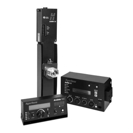
Specifications Introduction The Hypertherm ArcGlide THC is a voltage sensing, torch height control (THC) system that is designed for plasma cutting applications on an X-Y cutting machine. The system uses the plasma arc voltage to control the physical distance between the torch and the workpiece during cutting. Up to 4 ArcGlide systems can be installed on a cutting machine. -
Page 36: Arcglide Control Module
Lifter station ENABLE/DISABLE switch with an indicator lamp Manual UP/DOWN switch Laser pointer for workpiece alignment Signal interface cable Optional magnetic or pneumatic torch breakaway with circuitry to indicate a collision Optional torch mounting block ArcGlide THC Instruction Manual 806450... -
Page 37: Human Machine Interface (Hmi)
1. Precise, scaled feedback of the plasma arc voltage to the ArcGlide THC control module. 2. A convenient, control signal interface to the ArcGlide THC. Hypertherm offers 2 types of plasma interface boards. See Discrete plasma interface board (141094) on page 44 or Hypernet plasma interface board (141162) on page 45. -
Page 38: Specifications
Input power 115 VAC, 50/60 Hz, 1-phase 230 VAC, 50/60 Hz, 1-phase* Operating temperature -10ºC to 40ºC (14ºF to 104ºF) Operating humidity 95% relative humidity Warranty 2 years for electronics and lifter * Factory default setting ArcGlide THC Instruction Manual 806450... -
Page 39: Arcglide Control Module (090054)
(115 V or 230 V). ** Factory default setting Figure 2 157.23 mm (6.19 inch) 206.25 mm (8.12 inch) 381.00 mm (15.37 inch) 7.26 kg 358.65 mm (16.00 lb) (14.12 inch) ArcGlide THC Instruction Manual 806450... -
Page 40: Lifter Assembly (090053)
Maximum Z-axis stroke 239 mm (9.40 inch) Breakaway switch +24 VDC Motor brake +24 VDC Laser pointer (Class 3B) +5 VDC Maximum power: 500 mW Wavelength: 400 – 695 nm Lifter capacity 11.3 kg (25.0 lb) ArcGlide THC Instruction Manual 806450... - Page 41 4.5 kg (10 lb) magnetic 090090 35 mm (1.375 inch) 4.5 kg (10 lb) magnetic 090091 Not included Pneumatic 090092 Not included 4.5 kg (10 lb) magnetic 090093 Not included 11 kg (25 lb) magnetic ArcGlide THC Instruction Manual 806450...
- Page 42 1 – Specifications Figure 3 151.10 mm 78.70 mm (5.95 inch) (3.10 inch) 269.20 mm (10.60 inch) 744.20 mm (29.30 inch) 50.80 mm (2.00 inch) 14.00 kg (30.90 lb) 186.70 mm 149.10 mm (7.35 inch) (5.87 inch) ArcGlide THC Instruction Manual 806450...
-
Page 43: Optional Hmi (090055)
Shielded RJ-45 Cat5e or Cat6 Operating temperature -10ºC to 40ºC (14ºF to 104ºF) Operating humidity 95% relative humidity Figure 4 130.50 mm (5.14 inch) 117.60 mm (4.63 inch) 1.91 kg 298.00 mm (4.20 lb) (11.73 inch) ArcGlide THC Instruction Manual 806450... -
Page 44: Discrete Plasma Interface Board (141094)
(5.72 inch) 0.68 kg (1.50 lb) 27.69 mm (1.09 inch) Input power 24 V (AC or DC) Parallel digital I/O +12 VDC to +24 VDC Serial digital I/O 5 VDC Voltage divider ratio 50:1 Arc voltage ArcGlide THC Instruction Manual 806450... -
Page 45: Hypernet Plasma Interface Board (141162)
(6.75 inch) 145.29 mm (5.72 inch) 0.20 kg (0.45 lb) Input power 24 V (AC or DC) Parallel digital I/O +12 VDC to +24 VDC Serial digital I/O 5 VDC Voltage divider ratio 50:1 Arc voltage ArcGlide THC Instruction Manual 806450... -
Page 46: Ethernet Switch
1 – Specifications Ethernet switch If the ArcGlide THC has more than one connection to Hypernet that communicates with either the CNC or the plasma system, you must include an industrial grade Ethernet switch with multiple ports for communication between these components. - Page 47 4000 VDC Ethernet ESD protection, 3000 VDC surge (EFT) protection for the power line I/O transmission distance Up to 100 m (109 yard) (4-wire Cat5e or Cat6) I/O transmission speed 10/100 Mbps auto-negotiation Operating temperature -10ºC to 60ºC (14ºF to 140ºF) ArcGlide THC Instruction Manual 806450...
-
Page 48: Arcglide Communication
Hypernet component address. This address must correspond to the station number for the THC that is selected in Phoenix, on the Station Configuration screen. See Assign an ArcGlide THC to a station on page 125 for more information. - Page 49 THC and the ArcGlide plasma interface board in the plasma system. Within the plasma system, serial communication is carried between the ArcGlide plasma interface board and the plasma control board by a serial cable (123760). ArcGlide ArcGlide plasma Plasma interface control board board Hypernet Hypernet RS-422 Cat5e or Cat6 Cat5e or Cat6 ArcGlide THC Instruction Manual 806450...
-
Page 50: Discrete Communication
HMI, is connected to the ArcGlide control module with discrete cables. The HMI communicates with the control module using the Hypernet protocol over a shielded, Ethernet Cat5e or Cat6 cable. Figure 8 Lifter Plasma system Picopath CNC ArcGlide control module Plasma interface board Key: Hypernet connection Discrete connection ArcGlide THC Instruction Manual 806450... -
Page 51: Mixed Communication
Key: Hypernet connection Discrete connection Serial communication The ArcGlide THC supports an optional serial interface to a non-Hypernet CNC. See ArcGlide THC Serial Communication Installation on page 269 for more information on serial communication. ArcGlide THC Instruction Manual 806450... - Page 52 1 – Specifications ArcGlide THC Instruction Manual 806450...
-
Page 53: Installation
Claims for damage during shipment – If your unit was damaged during shipment, you must file a claim with the carrier. Hypertherm will furnish you with a copy of the bill of lading upon request. If you need additional assistance, call the nearest Hypertherm office listed in the front of this manual. -
Page 54: Installation Requirements
All installation and service of the electrical system must conform to national and local electrical codes. This work should be performed only by qualified, licensed personnel. Direct any technical questions to the nearest Hypertherm Technical Service office listed in the front of this manual, or to your table manufacturer. -
Page 55: Recommended Grounding And Shielding Practices
The diagram at the end of this section shows these types of grounds in a plasma cutting system. The grounding practices in this section have been used on many installations with excellent results, and Hypertherm recommends that these practices be a routine part of the installation process. The actual methods used to implement these practices may vary from system to system, but should remain as consistent as possible. - Page 56 9. Each Hypertherm component, as well as any other CNC or motor drive cabinet or enclosure, must have a separate ground cable to the common (star) ground on the table. This includes the ignition console, whether it is bolted to the plasma system or to the cutting table.
- Page 57 A single heavy cable then connects the gantry ground bus to the table ground bus. Cable to the cutting table ground bus Ground cables from components on the gantry ArcGlide THC Instruction Manual 806450...
- Page 58 12 System-specific component such as a cooler or 6 Torch height control lifter (ArcGlide, Sensor THC, chiller Sensor PHC, or other) 13 DC power ground 7 RHF console (not on all systems). Connect to table ground bus bar. ArcGlide THC Instruction Manual 806450...
-
Page 59: System Description For A Hypernet Configuration
Hypernet cables transmit serial communication. Figure 11 Key: Hypernet connection – – – – – – —————— Discrete connection ArcGlide control module HMI (optional) Industrial Ethernet switch ArcGlide lifter CNC with Hypernet HPR plasma system with Hypernet ArcGlide THC Instruction Manual 806450... -
Page 60: System Description For A Discrete Configuration
Figure 12 Key: – – – – – – Hypernet connection —————— Discrete connection ArcGlide control module HMI (optional) Customer-supplied operator console (optional): Station on/off/program switch Station active light Lifter UP/DOWN switch ArcGlide lifter Plasma system ArcGlide THC Instruction Manual 806450... -
Page 61: Arcglide Communication Configuration Examples
Discrete to Powermax plasma systems with Discrete to a CNC with a Picopath interface. page 72 plasma interface board 141094 and Powermax interface cable 023206 between the plasma interface board and the Powermax plasma system. ArcGlide THC Instruction Manual 806450... - Page 62 External wiring outside the electrical enclosure should be suitable for the installation and meet national and local regulations (for example, NFPA 70 NEC, NFPA 79, Canadian Electrical Code, CSA/CAN E60974-1, IEC 60204-1, BS 7671) or other codes or standards applicable to the installed site where the equipment will be operated. ArcGlide THC Instruction Manual 806450...
- Page 63 Hypernet plasma interface board Hypernet plasma interface board (141162) installed in the plasma system (141162) installed in the plasma system (below) (below) HPR130/HPR260 HPR130XD/HPR260XD HPR400XD/HPR800XD with built-in Hypernet adapter or optional ArcGlide lifters Hypernet kit (228611) or (228604) ArcGlide THC Instruction Manual 806450...
- Page 64 2 – Installation 2 – ArcGlide THC with Hypernet connection to a Hypernet-enabled CNC and discrete connection to an HPR130/260 or HPR130/260XD plasma system Rotary address switch, set to 1 EDGE Pro, EDGE Pro Ti, or MicroEDGE Pro CNC Shielded Ethernet cable up to 61 m (200 foot) long...
- Page 65 2 – Installation 3 – ArcGlide THC with discrete connection to a Picopath interface CNC and HPR130/260 or HPR130/260XD plasma system Rotary address switch, set to 1 Optional ArcGlide HMI Rotary address switch, set to 1 ArcGlide control module Picopath interface CNC...
- Page 66 2 – Installation 4 – ArcGlide THC with discrete connection to a generic CNC and HPR130/260 or HPR130/260XD plasma system Rotary address switch, set to 1 Rotary address switch, set to 1 Optional ArcGlide HMI ArcGlide control module Shielded Ethernet cable, up...
- Page 67 2 – Installation 5 – ArcGlide THC with discrete connection to a generic CNC and HPR400/800XD plasma system Rotary address switch, Rotary address switch, set to 1 set to 1 ArcGlide control module Optional ArcGlide HMI Shielded Ethernet cable, up...
- Page 68 ** Motion and Start are the minimum connections. Use other signals if they are J2-1 1 Motion** supported by the plasma system. To plasma system Work+ * 24 V pull-up resistors on inputs are active only if they are set to dry (D) on the ArcGlide control module ArcGlide THC Instruction Manual 806450...
- Page 69 2 – Installation 7 – ArcGlide THC with discrete communication to a Picopath interface CNC and HSD130 plasma system Rotary address switch, set to 1 Optional ArcGlide HMI Rotary address switch, set to 1 ArcGlide control module CNC with Picopath interface...
- Page 70 2 – Installation 8 – ArcGlide THC with discrete connections to a Picopath interface CNC and MAX200, HT2000, or HT2000 LHF plasma system Rotary address switch, set to 1 Rotary address switch, set to 1 Optional ArcGlide HMI ArcGlide control module...
- Page 71 ( * ) For HT2000, HT2000LHF To plasma system Plasma interface board (141094), mounted externally Work + by the customer Arc voltage sense wires to plasma system, use ~0.9 mm (18 AWG) twisted pair wire, rated 600 V or greater. ArcGlide THC Instruction Manual 806450...
- Page 72 Powermax Work+ See Field Service Bulletin 65/85/105/125 1000/1230/1650 65/85 CE Electrode- Machine Interface for Work+ Raw Arc Voltage 105/125 CSA or CE Electrode- For Work and Electrode connections, see the table at right. (807060) Work+ ArcGlide THC Instruction Manual 806450...
- Page 73 COMMON End A of the Hypertherm ArcGlide CNC I/O cable is terminated during installation and will work only if the I/O setup in Phoenix software corresponds to the setup End B of the Hypertherm ArcGlide CNC I/O cable is terminated at the described in this half of this table.
- Page 74 J2-1 are supported by the plasma system. 1 Motion** * 24 V pull-up resistors on inputs are active only if they are set to dry (D) on the THC processor board in the control module. ArcGlide THC Instruction Manual 806450...
- Page 75 2 – Installation 13 – ArcGlide THC with Hypernet connection to an EDGE Pro CNC and MAXPRO200 plasma system Rotary address switch, set to 1 ArcGlide control module Rotary address switch, set to 1 Optional ArcGlide HMI Shielded Ethernet cables, up...
- Page 76 2 – Installation 14 – ArcGlide THC with discrete connection to a Picopath interface CNC and MAXPRO200 plasma system Rotary address switch, set to 1 Optional ArcGlide HMI Rotary address switch, set to 1 ArcGlide control module Lifter I/O cable...
-
Page 77: Install The Lifter
44.45 mm (1.75 inch) 44.45 mm (1.75 inch) 44.45 mm (1.75 inch) 44.45 mm (1.75 inch) 44.45 mm (1.75 inch) 44.45 mm (1.75 inch) 44.45 mm (1.75 inch) 6.75 mm (0.27 inch) diameter 114.30 mm (4.5 inch) ArcGlide THC Instruction Manual 806450... - Page 78 Use the cable clamp that is included with the lifter to secure the cable to either side of the lifter with a generous service loop. c. Connect the cable ground to the ground connector on the top of the lifter. ArcGlide THC Instruction Manual 806450...
-
Page 79: Connect The Ohmic Wire From Hprxd Plasma Systems
6. Insert the stripped HPRXD ohmic wire into the J5 connector on the underside of the lifter interface board. 7. Use cable ties to fasten the wire to the mounts on the inside back wall of the lifter compartment. 8. Replace the top cover of the motor compartment. ArcGlide THC Instruction Manual 806450... -
Page 80: Connect The Ohmic Wire To Other Plasma Systems
4. Connect the other end of the ground wire to a terminal on the table ground bus bar on the cutting machine. 5. Verify that the wire is not in the path of the lifter mechanics See Recommended grounding and shielding practices on page 55 for more information. ArcGlide THC Instruction Manual 806450... -
Page 81: Extended Torch Sleeve Option
(220790) 228.60 mm (9.00 inch) 355.60 mm (14.00 inch) 127.00 mm (5.00 inch) 228.60 mm (9.00 inch) 111.76 mm 355.60 mm (4.40 inch) (14.00 inch) 239 mm (9.40 inch) ArcGlide THC Instruction Manual 806450... -
Page 82: Install The Optional Pneumatic Breakaway
3. Attach the torch mounting block to the breakaway with the collar and 2 screws. 4. Wire the electrical output of the breakaway to the torch collision input of the CNC. 5. Mount the filter/regulator. 6. Connect the tubing between the filter/regulator and the breakaway. ArcGlide THC Instruction Manual 806450... - Page 83 10. Manually reposition the breakaway in the locked position. 11. Adjust the air pressure until the desired trip force is achieved. 12. Enable the emergency stop circuit at the CNC after the breakaway is installed. ArcGlide THC Instruction Manual 806450...
-
Page 84: Install The Control Module
166.62 mm (6.56 inch) Right side view 371.35 mm (14.62 inch) 165.00 mm (6.50 inch) 5.10 mm (0.20 inch) wide 127.00 mm (5.00 inch) 6.35 mm (0.25 inch) bolt 377.70 mm (14.87 inch) Rear view ArcGlide THC Instruction Manual 806450... -
Page 85: Modify Retract Delay Time For An Ht2000 Plasma System
Modify Retract Delay Time for an HT2000 plasma system If you are installing an ArcGlide THC with an HT2000 plasma system, set switch 1 on the auxiliary DIP switch options ( ) to ON on the THC processor board (228578) in the control module. This setting modifies Retract Delay Time for correct operation. -
Page 86: Ground The Control Module
4. Connect the other end of the ground wire to a terminal on the table ground bus bar on the cutting machine. See Recommended grounding and shielding practices on page 55 for more information. Figure 19 See Operating the control module on page 135 for more information. ArcGlide THC Instruction Manual 806450... -
Page 87: Install The Optional Hmi
19.43 mm Front view 117.60 mm 9.55 mm (0.375 inch) (0.77 inch) (4.63 inch) (0.38 inch) Phillips screw Right side view 203.20 mm (8.00 inch) 5.00 mm (0.20 inch) diameter Bottom view 63.50 mm (2.50 inch) ArcGlide THC Instruction Manual 806450... - Page 88 You can also mount the HMI on top of the EDGE Pro CNC. The EDGE Pro enclosure has 4 mounting holes for the HMI bracket. Use 4 10-32 x 1/2 inch screws to fasten the HMI to the EDGE Pro CNC enclosure. ArcGlide THC Instruction Manual 806450...
-
Page 89: Ground The Hmi
4. Connect the other end of the ground wire to a terminal on the gantry ground bus bar of the cutting machine. See Recommended grounding and shielding practices on page 55 for more information. Figure 22 See Operating the HMI on page 143 for more information. ArcGlide THC Instruction Manual 806450... -
Page 90: Install The Plasma Interface Board In A Plasma System
The plasma interface board includes the voltage divider and allows the ArcGlide THC to communicate with the plasma system. If you are replacing a Command THC with an ArcGlide THC, you must replace the Command THC plasma interface board in your plasma system with an ArcGlide plasma interface board. -
Page 91: Hypernet Plasma Interface Board (141162)
The Hypernet plasma interface board is mounted inside an HPRXD plasma system on standoffs built into the plasma system, as shown in Figure 24. Figure 24 Hypernet plasma interface board HPR130XD and HPR260XD HPR400XD See Hypernet plasma interface board (141162) on page 228 for information about electrical installation. ArcGlide THC Instruction Manual 806450... -
Page 92: Connect Hypernet Cables
Discrete connection See the following pages for details: See Assign an ArcGlide THC to a station on page 125 for information about linking unit addresses to a station in Phoenix software on a Hypertherm CNC. See the following sections for the location of the unit address switches: ... - Page 93 Hypernet connections to the Ethernet switch It is also possible to have a mixed Hypernet and discrete configuration in which the ArcGlide THC communicates with only the CNC or plasma system over Hypernet and uses discrete communication for the alternate connection. See Mixed communication on page 51.
- Page 94 Insert one end of the Hypernet cable into the Hypernet port on the HMI. b. Insert the other end of the cable into one of the ports of the Ethernet switch. To the Ethernet switch ArcGlide THC Instruction Manual 806450...
-
Page 95: Connect Discrete Cables
Figure 12 on page 60. It is also possible to have a mixed Hypernet and discrete configuration in which the ArcGlide THC communicates with the CNC or the plasma system over a discrete connection and uses Hypernet communication for the remaining connection. - Page 96 See Optional operator console I/O cable on page 101 for more information. console 5. See Install the lifter on page 77 for more information on connecting the ArcGlide lifter to the control module. Connection to the lifter ArcGlide THC Instruction Manual 806450...
-
Page 97: Cables
Power cable An AC power cable is standard equipment for North America, and is shipped with the ArcGlide THC. For other regions, use a power cable that has an IEC-60320-C13 end which meets the requirements of local code and power connections. -
Page 98: Lifter Interface Cable
(22 AWG) Encoder input B - Blue 0.33 mm (22 AWG) Encoder input B + White/Yellow 0.33 mm (22 AWG) Encoder input A - * Pin numbers are the same on both ends of the cable. ArcGlide THC Instruction Manual 806450... - Page 99 White/Green 0.33 mm (22 AWG) Lower limit switch + White/Gray 0.33 mm (22 AWG) Not connected White/Brown 0.33 mm (22 AWG) Common - Not connected * Pin numbers are the same on both ends of the cable. ArcGlide THC Instruction Manual 806450...
-
Page 100: Hypernet And Hmi Interface Cable
Tx - (transmit data -) Rx + (receive data +) Not connected Not connected Rx - (receive data -) Not connected Not connected * Pin numbers are the same on both ends of the cable. ArcGlide THC Instruction Manual 806450... -
Page 101: Optional Operator Console I/O Cable
45.5 m (150 feet) 223218 10.5 m (35 feet) 223114 61.0 m (200 feet) 223006 15.0 m (50 feet) See Optional operator console I/O signals on page 103 for more information about discrete operator console I/O signals. ArcGlide THC Instruction Manual 806450... - Page 102 +24 V Pin numbers are the same on both ends of the cable. Input signals (pins 2 – 6) use 24 VDC; Output signals (pins 8 – 14) use dry contact closures at 24 VDC. ArcGlide THC Instruction Manual 806450...
-
Page 103: Optional Operator Console I/O Signals
IHS speed. After an additional second, the motion accelerates to the intermediate programmed speed. If the torch is in the process of cutting, this input decreases the voltage setpoint at a rate of 0.2 V every 1/4 second. ArcGlide THC Instruction Manual 806450... -
Page 104: Arcglide Control Module Cnc Interlock Kit (228594)
A closed circuit between pins 25 and 26 is required to satisfy the interlock circuit and enable the Z-axis motion of the ArcGlide. The interlock kit includes the connector, backshell, and pins that are necessary to build the interlock. ArcGlide THC Instruction Manual 806450... -
Page 105: Cnc I/O Cable
45.5 m (150 feet) 223215 10.5 m (35 feet) 223110 61.0 m (200 feet) 223005 15.0 m (50 feet) See CNC discrete I/O on page 108 for more information about discrete CNC I/O signals. ArcGlide THC Instruction Manual 806450... - Page 106 Spare input 1 - Brown Spare input 2 + +24 V 3.9 K 3.9 K 3.9 K Black Spare input 2 - Pin numbers are the same on both ends of the cable. AVC = Arc voltage control ArcGlide THC Instruction Manual 806450...
- Page 107 +24 VDC output +24 V Orange +24 VDC output +24 V Not connected Not connected Pin numbers are the same on both ends of the cable. The circuit is closed if a jumper is used. ArcGlide THC Instruction Manual 806450...
-
Page 108: Cnc Discrete I/O
CNC and the CNC should remove all Hold Ignition input signals and allow all active plasma torches to ignite simultaneously. Spare inputs 1 and 2: These inputs to the ArcGlide are reserved and should not be connected. ArcGlide THC Instruction Manual 806450... - Page 109 ArcGlide lifter motor drive will lose power. This circuit must be wired according to national and local regulations. Interlock output: The Interlock output is an independent contact closure that is also normally-closed. The Interlock output must have the same state as the Interlock input. ArcGlide THC Instruction Manual 806450...
-
Page 110: Plasma Interface I/O Cable
45.5 m (150 feet) 223229 10.5 m (35 feet) 223106 61.0 m (200 feet) 223004 15.0 m (50 feet) See Plasma discrete I/O on page 113 for more information about discrete plasma I/O signals. ArcGlide THC Instruction Manual 806450... - Page 111 3.9 K Orange Not ready input - Black Spare input + +24 V 3.9 K 3.9 K 3.9 K White Spare input - * Pin numbers are the same on both ends of the cable. ArcGlide THC Instruction Manual 806450...
- Page 112 +24 V Brown +24 VDC output +24 V Green 1/50 Arc voltage + Orange 1/50 Arc voltage - 36 to 50 Not connected * Pin numbers are the same on both ends of the cable. ArcGlide THC Instruction Manual 806450...
-
Page 113: Plasma Discrete I/O
Dry or sourced plasma input switch The following discrete signals are used to connect the ArcGlide THC to the plasma system. All the required discrete interface signals between the control module and the plasma system are described below. All other signals are optional for multiple torch operation, improved performance, or reduction in cycle times. - Page 114 Spare output: This is an extra output for future use. Remote On: This is an optional output signal from the ArcGlide THC that can be used to turn ON or OFF capable plasma systems. On capable systems, such as the HPR plasma systems, deactivating this signal will remove the high power input to the plasma system and will turn off the gas and torch cooling pump.
-
Page 115: Non-Serial Plasma Interface Cable
Hold B Green Plasma Start relay A Yellow Plasma Start relay B Green Remote ON A Brown Remote ON B Green Not connected Orange Ground White Ground Black +24 VDC HPR plasma Blue Not connected Ground ArcGlide THC Instruction Manual 806450... -
Page 116: Serial Plasma Interface Cable
Serial plasma interface cable This cable connects the ArcGlide plasma interface board and control board inside the plasma system. Use this cable when the ArcGlide THC supplies serial communication to the plasma system. Diameter = 9.65 mm (0.38 inch) Bend radius = 152.40 mm (6.00 inch) -
Page 117: Arcglide Discrete Interface Signal Examples
2 – Installation ArcGlide discrete interface signal examples Inputs Figure 30 shows a simplified schematic of the ArcGlide THC inputs. The inputs for both CNC and plasma can be configured for dry contacts (no external voltage) or for positive voltage sourced inputs. -
Page 118: Relay Outputs
Relay outputs Most of the ArcGlide THC outputs are relay contacts and can be used for either AC or DC loads. All relay outputs are protected with thermal fuses that automatically reset and protect against currents above 100 mA. The 24 V supply is limited to a total of 2 A for all outputs. -
Page 119: Arcglide Setup In Phoenix™ Software
ArcGlide setup in Phoenix™ software If you are installing the ArcGlide THC hardware with a Hypertherm CNC and Phoenix software (version 9.5 or later) and the Hypernet interface, refer to the Phoenix Software V9 Series Installation and Setup Manual (806410) for complete information. -
Page 120: Arcglide Axis Setup
The default values for each parameter on the ArcGlide axes screens are optimized for the majority of applications. However, you may need to adjust the following parameter values: Stall Force Pointer Offset Side Pointer Offset Front Voltage Calibration Figure 33 ArcGlide THC Instruction Manual 806450... -
Page 121: Arcglide Axis Setup Parameters
To optimize this gain, raise the value until there is a very slight oscillation when the torch settles into the IHS or Retract positions and then reduce the setting by 1. Range: 1 to 10; Setting: 5 ArcGlide THC Instruction Manual 806450... -
Page 122: Speeds
For the Hypertherm 239 mm (9.40 inch) lifter, this value is 15240 mm/min (600 in/min). At the low input line voltage limit, the motor drive is capable of supplying about 45 VDC. The motor used in the Hypertherm 239 mm (9.40 inch) lifter will produce full-rated torque at about 3,300 r/min at this voltage. -
Page 123: Mechanical
IHS operation. With the Hypertherm 239 mm (9.40-inch) lifter, the value of 5 is appropriate. It may be necessary to reduce this value if the THC is used with a thin workpiece. Use the Test IHS function to optimize this value. -
Page 124: Miscellaneous
Arc On, If the input does not activate within 10 seconds, the ignition process stops, the torch retracts, and the IHS starts again with another attempt to ignite the torch. The CNC repeats this sequence twice. Options: Yes, No ArcGlide THC Instruction Manual 806450... -
Page 125: Assign An Arcglide Thc To A Station
2. Choose Setups > Password > Station Configuration. 3. Choose Reset if ArcGlide THC does not appear in the Lifter dropdown list. 4. On the Station Configuration screen, shown in Figure 34, select ArcGlide THC for each station where an ArcGlide is installed. - Page 126 2 – Installation ArcGlide THC Instruction Manual 806450...
-
Page 127: Operation
These LEDs show the status of system operations. Display window This window displays status, error, and diagnostic messages. Display select Push the UP or DOWN arrow to scroll up or down through the screens in the display window. ArcGlide THC Instruction Manual 806450... -
Page 128: Lifter
If the plasma system allows the THC to turn it on and off and is wired appropriately, this switch can turn ON and OFF the plasma system. Lifter UP/DOWN Push this switch up or down to raise or lower the torch. switch ArcGlide THC Instruction Manual 806450... -
Page 129: Hmi
LED does not illuminate during ohmic contact, see the description and solution for Error 21 in ArcGlide errors on page 191. Arc voltage window This window displays the actual arc voltage or OFF if the lifter is disabled. ArcGlide THC Instruction Manual 806450... -
Page 130: Daily Operations
If you disable the ArcGlide with the ENABLE/DISABLE switch on the lifter unit, the plasma system will also turn off. If you are using the HPR Remote On or Off feature with the ArcGlide THC, do not disconnect the power cord on the ArcGlide control module to turn OFF the ArcGlide THC. -
Page 131: Arcglide Thc Operating Modes
Manual mode The ArcGlide THC can be operated in Manual mode for special circumstances. In Manual mode, there is no THC motion unless it is initiated by the manual UP/DOWN switch on the HMI or CNC. This mode is rarely used because the torch will fire in the air if it is not close enough to the workpiece to transfer the arc. -
Page 132: Voltage Control Off Mode
This mode requires an accurate IHS and voltage sample. In addition, when Sample Voltage mode is on, the CNC does not use the Set Arc Voltage from the cut chart. To enable Sample Voltage mode for the ArcGlide, choose Automatic and set Sample Voltage to ON. ArcGlide THC Instruction Manual 806450... -
Page 133: Initial Height Sense
Performing a first IHS on the ArcGlide Press the IHS test on the ArcGlide HMI to perform a first IHS. To perform a first IHS on a Hypertherm CNC, choose the Test Lifter soft key. The ArcGlide moves to the workpiece at the Slow IHS speed. On subsequent IHSs, the ArcGlide uses the Fast Speed until it reaches the Start IHS height. - Page 134 Figure 35 12 13 Tip touch Retract complete Cut Off time Torch path Plasma start Pierce delay CNC cut control active IHS start height Arc transfer Cut height delay Plasma torch active Puddle jump height Creep time AVC delay Cutting X/Y motion Pierce height Cut height AVC sampling...
-
Page 135: Operating The Control Module
You cannot set parameters through the control module using Hypernet or discrete communication. However, if your system includes a CNC that is not a Hypertherm CNC, you can set parameters on the control module with RS-422 communication and commands. See ArcGlide THC Serial Communication Protocol on page 249 for more information. -
Page 136: Screen 0 - Idle Park
Go To Transfer Ht IHS Complete Start Plasma, Wait Xfer Go To Pierce Start Piercing Go To Puddle Jump Ht Cut Ht Accel State V Sample State Cutting Ramp Down Manual Up Manual Down End Of Cut Retract ArcGlide THC Instruction Manual 806450... -
Page 137: Screen 2 - Options
0.001 in Mode: Displays the operating mode of the ArcGlide THC (Auto or Manual) that was selected at the HMI or CNC. Set Volts: Displays the voltage setting from the CNC or HMI if sample voltage mode is not enabled. -
Page 138: Screen 3 - Inputs From The Cnc
THC Error: Indicates that there is an error at the THC. See Screen 11 – Last errors on page 142 for more information. On/Off Torch Breakaway: The breakaway sensor has detected a torch collision. On/Off Spare: Reserved ArcGlide THC Instruction Manual 806450... -
Page 139: Screen 5 - Inputs From The Lifter Control Board
TIP-TOUCH LED on the front of the control module. On/Off Brake: Indicates that the lifter brake is activated. On/Off Motor: Indicates that the lifter motor is operating. On/Off ArcGlide THC Instruction Manual 806450... -
Page 140: Screen 7 - Inputs From The Operator Console
Torch Enable: Indicates that the torch is enabled at the lifter. On/Off Error: Indicates that there is an ArcGlide error. See Screen 11 – Last errors on page 142 for more information. On/Off Spare: Reserved ArcGlide THC Instruction Manual 806450... -
Page 141: Screen 9 - Inputs From The Plasma System
Hold: Indicates that the Hold output is preventing the plasma system from firing the torch. On/Off Start: Indicates that a Start signal is being sent to the plasma system. On/Off Remote On: Shows that the Remote ON output is active. On/Off ArcGlide THC Instruction Manual 806450... -
Page 142: Screen 11 - Last Errors
Last No error Lists the most recent 3 changes in ArcGlide error conditions, including “No error. ” Screen 12 – Total lifter operating time Total Lifter Operating Time 50 Hours Service lifter every 500 hours ArcGlide THC Instruction Manual 806450... -
Page 143: Operating The Hmi
If your cutting machine does not include a CNC connected with Hypernet, the HMI is required so an operator can control the ArcGlide THC. On the HMI, the operator can set parameters, read error and diagnostic messages, and manually control the position of the torch. -
Page 144: Hmi Screen Hierarchy
Switch Diagnostics Slide Length Max Servo Current Encoder Counts/in Max Speed/min Fast Speed Slow Speed Installation Data IHS Speed Relative Speed Gain Relative Position Gain Relative Arc Volts Gain Arc Voltage Calibration Display Units Languages ArcGlide THC Instruction Manual 806450... - Page 145 Max Servo Current Encoder Counts/in Max Speed/min Fast Speed Slow Speed Installation Data IHS Speed Relative Speed Gain Relative Position Gain Relative Arc Volts Gain Arc Voltage Calibration Display Units Languages Arc Starts Disabled mode Arc Minutes ArcGlide THC Instruction Manual 806450...
-
Page 146: Main Screen
(OFF), the torch height sequences in Auto mode (IHS, Cut Height, Retract) but the torch height does not change based on arc voltage and remains constant during the cut. Default = ON. <Setup Parameters> Select this line to display the Setup Parameters menu. ArcGlide THC Instruction Manual 806450... -
Page 147: Setup Screen
Default = ON. Kerf Level: This parameter sets a sensitivity threshold to detect kerf. The range is 1 (more sensitive) – 10 (less sensitive). Default = 5. ArcGlide THC Instruction Manual 806450... -
Page 148: Diagnostics Screen
ERR 4 PLATE CONTACT AT HOME – Ohmic contact with the workpiece at home position – an invalid condition. ERR 5 HOME LIM DURING OPR – The lifter reached the home (upper) limit during auto operation. ArcGlide THC Instruction Manual 806450... - Page 149 ERR 28 BREAKAWAY TRIPPED – The torch breakaway was removed. ERR 29 FIELD SUPPLY FAILED – The +5 V, +12 V, or -12 V supply has failed. ERR 30 STALL CALIBRATION – Stall Calibration down motion failed after power was turned ON. ArcGlide THC Instruction Manual 806450...
- Page 150 Slide Length. The motor is stopped and the torch maintains its position. Only up motion is allowed during this state. An error message displays if the THC enters this state during automatic operation. ArcGlide THC Instruction Manual 806450...
- Page 151 MANUAL UP – The lifter initially jogs up 0.254 mm (0.01 inch). After 0.5 second, it begins continuous upward motion at the IHS Speed. After 2 seconds, the lifter increases the speed to the programmed Slow Speed. Outputs do not change; if the torch is already cutting, it continues to cut. ArcGlide THC Instruction Manual 806450...
- Page 152 Switch Diagnostics: Allows the operator to test the status of the switches on the front panel of the HMI. ON or OFF displays as each switch is pushed or moved. <back> Select this line to return to the Main screen. ArcGlide THC Instruction Manual 806450...
-
Page 153: Installation Data Screen
Relative Speed Gain: This gain value regulates the speed of the lifter. Default = 5. Relative Position Gain: This gain is used for closed loop positioning. Default = 5 Relative ARC Volts Gain: This gain is used when the THC is operating closed-loop arc voltage control. Default = 5. ArcGlide THC Instruction Manual 806450... - Page 154 Display Units: The unit of measurement, inch or millimeter, that are used in the display. Default = inch. Language: The language selected for the display. Options are English, German, Portuguese, Spanish. Default = English. <back> Select this line to return to the Main screen. ArcGlide THC Instruction Manual 806450...
-
Page 155: Manual Mode
Arc Starts: The number of times the arc has started since the last time consumables were changed and the counter was restarted. Arc Minutes: The number of minutes of active cutting since the last time consumables were changed and the counter was restarted. ArcGlide THC Instruction Manual 806450... -
Page 156: Arcglide Operating Parameters
See the Phoenix Software Operator Manual (806400) for more information on these parameters in Phoenix. There are 4 sets of parameters on the Process screen: THC mode Cut chart values Options Automatically-set parameters ArcGlide THC Instruction Manual 806450... -
Page 157: Thc Mode
However, these changes are not saved in the cut chart. Set Arc Voltage: The ArcGlide THC must be in Automatic mode, Voltage Control must be ON, and Sample Voltage must be OFF. -
Page 158: Options
Start and Hold Ignition signals to the plasma system early to allow the gas preflow to occur while the THC is performing an IHS operation. This reduces the time required to move to the next part and start cutting. Setting: Off/On ArcGlide THC Instruction Manual 806450... - Page 159 3 – Operation IHS Start Height: This is the height above the workpiece where the THC starts the initial height sense process. When the torch reaches this distance above the workpiece, the following actions occur on Hypertherm CNCs: Speed slows from Maximum THC Speed to Fast IHS Speed.
- Page 160 Setting: 0 seconds to 10 seconds Retract Height: This parameter specifies the height above the workpiece to which the torch retracts at the end of a cut. Setting: 2.54 mm (0.10 inch) to the maximum lifter length ArcGlide THC Instruction Manual 806450...
-
Page 161: Plasma Cutting Tips
Positive cut angle: More material is removed from the top of the cut surface than from the bottom. Negative cut angle: More material is removed from the bottom of the cut surface than from the top. ArcGlide THC Instruction Manual 806450... - Page 162 In addition, vertical lag lines may be present; dross is easy to remove and flakes off in large chunks. Top spatter: A light spatter of molten material collects on the top edges of the cut. Usually, this spatter is inconsequential and is most common with air plasma. ArcGlide THC Instruction Manual 806450...
- Page 163 Weldable edge Color Color results from a chemical reaction between a metal and the plasma gas that is used to cut it. Color changes are to be expected and vary most dramatically with stainless steel. ArcGlide THC Instruction Manual 806450...
-
Page 164: Basic Steps To Improve Cut Quality
Adjust the cutting direction, if necessary. The plasma arc typically spins clockwise with standard consumables. Contour The torch travels clockwise. The good side of the cut is to the right side of the torch, as it travels forward. ArcGlide THC Instruction Manual 806450... - Page 165 Step 2: Was the correct process selected for the material and thickness being cut? Refer to the cut charts in the Operation section of the Hypertherm Instruction Manual. On the CNC, choose the Cut Chart soft key on the Main Screen to view the cut chart for the selected torch type, material and thickness.
- Page 166 Always replace the nozzle and electrode at the same time. Avoid over-lubricating o-rings. Use genuine Hypertherm consumables to ensure maximum cutting performance. Step 4: Is the torch perpendicular to the workpiece? Level the workpiece. Make the torch perpendicular to the workpiece, both from the front and side of the torch.
- Page 167 Consult the table manufacturer, your table may require maintenance. Step 9: Does the table need to be tuned? Check and ensure that the table is cutting at the specified speed. Consult the table manufacturer; the table speed may need tuning. ArcGlide THC Instruction Manual 806450...
- Page 168 3 – Operation ArcGlide THC Instruction Manual 806450...
-
Page 169: Maintenance
Section 4 Maintenance Introduction Hypertherm assumes that the service personnel who perform the troubleshooting testing are high-level electronic service technicians who have worked with high-voltage electro-mechanical systems. Knowledge of final isolation troubleshooting techniques is also assumed. In addition to being technically qualified, maintenance personnel must perform all testing with safety in mind. See Safety on page 13 for more safety precautions. - Page 170 To lubricate with a hand press, weigh out the quantity of grease in each stroke. 4. Inject 0.7 g (0.025 oz) of grease into one of the lubrication nipples. If you are using the Hypertherm grease gun (428259), one pump of the gun is equivalent to 0.7 g (0.025 oz). You do not need to lubricate the carriage on both sides.
-
Page 171: Sealing Strip
55. Examine the work lead (+) connection, particularly where the work lead (+) connects to the cutting machine. This must be a good, clean connection because a poor connection can interfere with arc transfer. ArcGlide THC Instruction Manual 806450... -
Page 172: Calibrate Arc Voltage
Calibrate arc voltage ArcGlide THC arc voltage is calibrated at the factory as part of the manufacturing process. If you need to verify or recalibrate the arc voltage for multiple ArcGlide installations or for long torch leads, begin by adjusting the value of the Voltage Calibration parameter on the ArcGlide Axes screen. - Page 173 Use a small straight screwdriver to turn the slotted screw on the arc voltage potentiometer clockwise, to increase the voltage, or counterclockwise, to decrease the voltage. Arc voltage calibration potentiometer CNC PLASMA 11. Repeat the parameter and potentiometer calibration until the measured arc voltage and the displayed arc voltage are the same. ArcGlide THC Instruction Manual 806450...
-
Page 174: Flow Of Arcglide Operations
4 – Maintenance Flow of ArcGlide operations The flowchart on the following pages illustrates the sequence of states in the operation of an ArcGlide THC. Power ON reset Initialize uP clock, on-chip I/O, expansion I/O. Read stored setup parameters Setups were saved the last time the THC was from Flash. - Page 175 Station disabled. Plasma remote power OFF. Critical error? Plasma remote power ON. Plasma system Hypernet Use discrete wire plasma system operating link active? signals and arc voltage. Use Hypernet plasma system operating signals and arc voltage. ArcGlide THC Instruction Manual 806450...
- Page 176 This operating state? Set state outputs. Control lifter speed and position. Check for errors. Check for change to next state. See Diagnostics screen on This operating state? page 148 for a complete list of states. Main loop ArcGlide THC Instruction Manual 806450...
-
Page 177: Basic Flow For All Arcglide Operating States
Not the first time in this state. Error condition? Error = this error. Next state = error state. Change to new state? Next state = new state. Next state = this state Exit operating state ArcGlide THC Instruction Manual 806450... -
Page 178: Common Machine-Cutting Faults
Firing the torch in the air (beginning or ending the cut off of the workpiece surface). Starting at the edge is acceptable as long as the arc makes contact with the workpiece when started. ArcGlide THC Instruction Manual 806450... - Page 179 See Hypernet plasma interface board (141162) on page 228 for more information. If your cutting machine does not include a Hypertherm plasma system, refer to the instruction manual for your plasma system. ArcGlide THC Instruction Manual 806450...
-
Page 180: Update Arcglide Firmware
1. After you download the ArcGlide THC Firmware Update.zip file, unpack it in a directory on the laptop hard drive or on a USB memory stick. One of the files included is EthernetSetup.vbs. There are also some program image .bin files and Update.exe files to load the images. -
Page 181: Operator Tests
On the front of the HMI, push the IHS Test button. Each successive push of the button moves the torch between the transfer and retract heights. On a Hypertherm CNC, the IHS Test soft key on the Process screen performs the same function. ArcGlide THC Instruction Manual 806450... -
Page 182: Problems And Solutions
Verify that the THC is in Automatic Mode. If not, change the mode to Automatic. Verify that Stall Force is not set too low. Verify that IHS Speed is not set too high. Look for cable and hose obstructions that may stop movement. ArcGlide THC Instruction Manual 806450... - Page 183 Verify that Pierce Time is set correctly. The delay is set too long so that the torch dwells in the piercing position too long before machine motion. Verify that Machine Motion Out is active after Pierce Delay ends. ArcGlide THC Instruction Manual 806450...
- Page 184 Look for obstructions in the torch path and torch lead set. For True Hole applications, verify that these HPRXD features are installed: HPRXD control board and code HPRXD torch New torch leads Ohmic contact wire with correct routing. ArcGlide THC Instruction Manual 806450...
-
Page 185: Troubleshooting Routines
4 – Maintenance Troubleshooting routines Hypertherm CNC will not communicate with HPR plasma system Verify that all units are wired and turned ON. Check for a firmware update or protocol mismatch. Verify that Message Plasma PS via Hypernet is selected on the Machine screen in Phoenix. -
Page 186: Error 19 - Excess Plate Contact
Voltage ON? water table? is not cutting at or below the surface of the water and that water is not splashing up onto the torch shield. Continued on the Continued on the next page next page ArcGlide THC Instruction Manual 806450... - Page 187 On a Hypertherm Is Torch Height CNC, check the Disable supported Torch Height Disable by the CNC? settings on the Speeds screen. Verify that Torch Height Disable speed is the correct percentage of cut speed. ArcGlide THC Instruction Manual 806450...
-
Page 188: Error 21 - Ohmic Tip Sense
Monitor the lifter for machine slats for have an electrical preventing the torch smooth motion. damage or slag connection to the from reaching the Examine the lifter build-up. cutting machine? workpiece? motion for obstructions. Continued on next page ArcGlide THC Instruction Manual 806450... - Page 189 Examine the ohmic contact wire for damage Continued on next page ArcGlide THC Instruction Manual 806450...
- Page 190 The lifter interface board (228580) has failed and must be replaced. ArcGlide THC Instruction Manual 806450...
-
Page 191: Error Message Troubleshooting
Error message displays On the ArcGlide THC, error messages are displayed on both the HMI and the control module. In addition, on Hypertherm CNCs, a system error message window can be set up in the Watch Window. This window displays the last 5 system error messages. - Page 192 • If the lifter is not a Hypertherm lifter and the installation is new, change the encoder wiring to the control module. ArcGlide THC Instruction Manual 806450...
- Page 193 • Verify that the lifter and control module are grounded correctly. The lifter and control module should have separate ground wires between the ground stud on the lifter, control module, and star ground on the gantry or table. ArcGlide THC Instruction Manual 806450...
- Page 194 • The lower limit switch is faulty. • Go to the diagnostic screen on the Hypertherm CNC, HMI, or control module (See Screen 11 – Last errors on page 142). Monitor the operation of the lower limit switch. ArcGlide THC Instruction Manual 806450...
- Page 195 ON, examine the lifter cable for damage. The lifter cable could be faulty or there could be a faulty input to the control module. Call Hypertherm Technical Service for further assistance. • The nozzle and shield are •...
- Page 196 • If this is a new installation, make sure the are causing unstable motion. Gain settings for the lifter are correct in the Hypertherm CNC or in the HMI on the Installation Data screen. See ArcGlide axis setup parameters on page 121.
- Page 197 • Perform an IHS test and verify that the torch is retracting to the pierce height listed in the plasma system cut chart. • Verify that the Hypertherm CNC Arc Off Time is correct. A small time should be used, usually no longer than 0.1 seconds.
- Page 198 • The Gain settings in the control • Verify the Gain settings in the the Pierce Height after the module are set incorrectly. Hypertherm CNC or in the HMI, on the arc transfer and after a Installation Data screen. See ArcGlide reasonable amount of time.
- Page 199 • The Gain settings in the control • Verify that the Gain settings in the module are set incorrectly. Hypertherm CNC or in the HMI, on the Installation Data screen, are correct. See ArcGlide axis setup parameters on page 121.
- Page 200 • The wrong consumables are in the torch or the plasma system is using the wrong cutting process. • There is a problem with plasma • Verify that the plasma system does not system. have any gas leaks or restrictions. ArcGlide THC Instruction Manual 806450...
- Page 201 • The torch is operating in a water • If you are cutting in a water table, set table and the water is above the Nozzle Contact Cutting to OFF in the surface of the workpiece. Plasma Process screen. ArcGlide THC Instruction Manual 806450...
- Page 202 • Examine the ohmic contact wire for damage. • There is a problem with the • Check for correct consumables and that torch consumables. the consumables are installed correctly. ArcGlide THC Instruction Manual 806450...
- Page 203 If the problem continues, contact Hypertherm Technical Service. • A mechanical bind is preventing • Monitor the lifter for smooth motion. the torch from reaching the • Examine the lifter motion for workpiece. obstructions. ArcGlide THC Instruction Manual 806450...
- Page 204 Verify that air is the cabinet are not functioning. continuously circulating inside the cabinet. ArcGlide THC Instruction Manual 806450...
- Page 205 (relays, proximity switches, etc.) operate down one of the voltages. correctly. • The unit is overheating due to • If the unit is operating at a high high ambient temperatures. temperature, allow it to cool. ArcGlide THC Instruction Manual 806450...
- Page 206 • The Ethernet switch is not • Verify that the Ethernet switch is receiving power or not receiving correctly turned ON. it correctly. • Verify that all related units are turned ON and addressed to the unit number. ArcGlide THC Instruction Manual 806450...
- Page 207 121. • Monitor the operation of the motor and encoder from the diagnostic screen of the CNC or at control module (See Screen 6 – Outputs from the lifter control board on page 139). ArcGlide THC Instruction Manual 806450...
- Page 208 • Verify that the plasma system is disconnected between the turned ON The ArcGlide control control module, the Ethernet module lost the • Examine all Hypernet connections. switch, and the plasma system. Hypernet connection to the plasma system. ArcGlide THC Instruction Manual 806450...
-
Page 209: Printed Circuit Board (Pcb) Block Diagram For A Hypernet Configuration
HMI processor board Hypernet interface LCD character module Front panel LEDs Plasma interface board 7-segment display interface Hypernet interface Arc voltage Contact closure outputs from THC Contact closure inputs to THC Plasma interface HMI 7-segment display board ArcGlide THC Instruction Manual 806450... -
Page 210: Printed Circuit Board (Pcb) Block Diagram For A Discrete Configuration
HMI 7-segment display board Plasma interface board Discrete plasma interface Arc voltage Contact closure outputs from THC Contact closure inputs to THC Key: Hypernet connection – – – – – – ——— ——— Discrete connection ArcGlide THC Instruction Manual 806450... -
Page 211: Arcglide Pcbs
Test point No. Signal TP10 +2.5 VDC TP33 +3.3 VDC TP37 +5 VDC TP38 Ground J4 LCD character module Pin No. Signal Pin No. Signal E1 (lines 1 and 2) Not connected E2 (lines 3 and 4) ArcGlide THC Instruction Manual 806450... - Page 212 Signal +5 V Ground Not connected J10 IHS test push button Pin No. Signal Ground IHS test J11 Front panel rotary encoder input Pin No. Signal Ground Ground Pushbutton-A Output B Output A +5 V ArcGlide THC Instruction Manual 806450...
- Page 213 4 – Maintenance J12 Power connector Pin No. Signal +5 V Ground Common Not connected ArcGlide THC Instruction Manual 806450...
-
Page 214: Hmi 7-Segment Display Interface Board (228582)
Tens A Hundreds decimal point Hundreds G Hundreds F Hundreds E Hundreds D Hundreds C Hundreds B Hundreds A Thousands decimal point Thousands G Thousands F Thousands E Thousands D Thousands C Thousands B Thousands A ArcGlide THC Instruction Manual 806450... -
Page 215: Thc Control Interface Board (228577)
115 V input 1 115 V input 2 115 V input 3 115 V input 4 45 V output line 1 45 V output line 2 22 V output line 1 22 V output line2 ArcGlide THC Instruction Manual 806450... - Page 216 Operator console Torch Down input Ohmic contact sense common +5 VDC Ground Operator console spare input Power good low active Not connected Line Volts Not connected Actual current Not connected Not connected +5 VDC Ground ArcGlide THC Instruction Manual 806450...
- Page 217 Rampdown error input + Rampdown error input - Not ready input + Not ready input - Spare input + Spare input - Corner output A Corner output B Pierce output A Pierce output B Hold output A ArcGlide THC Instruction Manual 806450...
- Page 218 CNC spare output A CNC spare output B Interlock input + Interlock input - Interlock output A Interlock output B Common Common Common Common +24 VDC output +24 VDC output +24 VDC output Not connected Not connected ArcGlide THC Instruction Manual 806450...
- Page 219 Torch up switch input + Torch down switch input + Spare switch input + Common Torch enabled output A Torch enabled output B Error output A Error output B Spare output A Spare output B Power +24 VDC output ArcGlide THC Instruction Manual 806450...
-
Page 220: Thc Processor Board (228578)
Hypernet plasma interface boards. The default setting is 1. J2 Front panel LEDs Pin No. Signal Pin No. Signal +5 VDC +5 VDC Start LED Motion LED Limit LED AVC LED Error LED Contact LED Display backup Display advance ArcGlide THC Instruction Manual 806450... - Page 221 Operator console Torch Down input Ohmic contact sense common +5 VDC Ground Operator console spare input Power good low active Not connected Line volts Not connected Actual current Not connected Not connected +5 VDC Ground ArcGlide THC Instruction Manual 806450...
- Page 222 +5 VDC Ground J4 LCD power Pin No. Signal +5 V Ground Not connected J5 LCD character module Pin No. Signal Pin No. Signal E1 (lines 1 and 2) Not connected E2 (lines 3 and 4) ArcGlide THC Instruction Manual 806450...
- Page 223 Tx - (transmit data -) Rx + (receive data +) Not connected Not connected Rx - (receive data -) Not connected Not connected J11 +5 V power Pin No. Signal +5 VDC Ground Common Not connected ArcGlide THC Instruction Manual 806450...
-
Page 224: Discrete Plasma Interface Board (141094)
* If the THC control board is configured with dry contacts, LED operation on the discrete plasma interface board is reversed and the LEDs will turn OFF when input is active. See THC processor board (228578) on page 220 for the location of this switch. ArcGlide THC Instruction Manual 806450... - Page 225 Spare input Common Common Common Common Common Plasma system 24 VAC line* Plasma system 24 VAC neutral** * Pin 15 can be changed to +24 VDC. ** Pin 16 can be changed to -24 VDC. ArcGlide THC Instruction Manual 806450...
- Page 226 The arc voltage terminals on connector J4 must be connected to the I/O board in an HPR plasma system. Connect pins 11 and 12 to locations 1 and 3 on terminal block 2 in an HPR plasma system Connect the arc voltage terminals to the I/O board in an HPR plasma system. ArcGlide THC Instruction Manual 806450...
- Page 227 Spare output B Remote on output A Remote on output B Common Common Common +24 VDC +24 VDC +24 VDC 1/50 Arc voltage + 1/50 Arc voltage - Not connected 37 – 50 Not connected ArcGlide THC Instruction Manual 806450...
-
Page 228: Hypernet Plasma Interface Board (141162)
In a Hypernet configuration, the Unit address switch (SW1) on the Hypernet interface board must have the same address as the Unit address switch on the HMI processor and the THC processor boards. The default setting is 1. ArcGlide THC Instruction Manual 806450... - Page 229 Not connected Not connected Not connected Spare Pierce A Hold A Start A Not connected Not connected Ground Not connected HPR Rx + HPR Tx + Not connected Motion Error Rampdown error HPR not ready ArcGlide THC Instruction Manual 806450...
- Page 230 Not connected Spare Pierce B Hold B Start B Not connected Ground Not connected J6 Remote ON/OFF Pin No. Signal ON/OFF out + ON/OFF out - J7 24 VAC Pin No. Signal Ground 24 VAC ArcGlide THC Instruction Manual 806450...
-
Page 231: Lifter Interface Board (228580)
J7 Laser pointer J4 Breakaway J6 Motor brake encoder Torch tip (ohmic wire) J3 Lower limit switch J1 Upper limit switch J2 LED J1 Upper limit switch Pin No. Signal +12 VDC Upper limit switch Common ArcGlide THC Instruction Manual 806450... - Page 232 Motor - Not connected Not connected Brake +24 VDC Brake switch return +5 VDC Phase A + Phase A - Phase B + Phase B - Common J7 Laser pointer Pin No. Signal +5 VDC Common ArcGlide THC Instruction Manual 806450...
- Page 233 Encoder input A - Encoder input A + Field common Change consumable switch + Lifter down switch + Lifter up switch + Breakaway switch + Upper limit switch + Lower limit switch + Not connected Common Not connected ArcGlide THC Instruction Manual 806450...
- Page 234 4 – Maintenance ArcGlide THC Instruction Manual 806450...
-
Page 235: Parts List
Section 5 Parts List Lifter parts Item Kit number Description Quantity 228588 Station Enable 5 V LED 228585 ENABLE/DISABLE switch 228584 Torch lifter UP/DOWN switch 228592 Laser pointer diode ArcGlide THC Instruction Manual 806450... - Page 236 228940 Magnetic breakaway retaining tether 128277 35 mm (1-3/8 inch) torch mounting block 120596 44.5 mm (1-3/4 inch) torch mounting block 120597 50 mm (2 inch) torch mounting block 228608 Breakaway cable and sensor ArcGlide THC Instruction Manual 806450...
-
Page 237: Lifter Motor And Slide Parts
Lifter interface board 428302 Lifter motor 428259 Grease gun 228591 Lifter slide 428245 Sealing band 228587 Lifter upper limit proximity switch 228586 Lifter lower limit proximity switch 428242 Ohmic contact wire 428241 Lifter side shields ArcGlide THC Instruction Manual 806450... -
Page 238: Control Module Parts
230 V surge board 228590 120 VAC, 5 V, 5 A, 25 W power source 008756 5 A, 250 V, 1/4 inch X 1-1/4 inch slow blow fuse 108842 Power cable connector 008197 AMP Pin extractor tool ArcGlide THC Instruction Manual 806450... -
Page 239: Hmi Parts
Kit number Description Quantity 228589 LCD display 228583 Momentary pushbutton switch 228582 HMI 7-segment display board 228579 230 V surge board 228590 120 VAC, 5 V, 5 A, 25 W power source 228581 HMI processor board ArcGlide THC Instruction Manual 806450... -
Page 240: Plasma Interface Boards
Discrete plasma interface board subassembly 228572 Discrete plasma interface board subassembly and metal enclosure 228604 Hypernet upgrade kit for HPR400XD and HPR800XD 228611 Hypernet upgrade kit for HPR130XD and HPR260XD 428276 Hypernet upgrade kit for MAXPRO200 ArcGlide THC Instruction Manual 806450... -
Page 241: Wiring Diagrams
Use the sheet number to find the reference sheet. Line up the coordinates A–D on the Y axis and numbers 1–4 on the X axis of each sheet to find the reference blocks (similar to a road map). ArcGlide THC Instruction Manual 806450... -
Page 242: Wiring Diagram Symbols
Diode Socket Shield Door interlock Plug Shunt PNP transistor Spark gap Feed-through LC Potentiometer Switch, flow Push button, Switch, level, Filter, AC normally closed normally closed Push button, Switch, pressure, Fuse normally open normally closed ArcGlide THC Instruction Manual 806450... - Page 243 Switch, 1 pole, 2 throw, Transformer center off Switch, temperature, Transformer, air core normally closed Switch, temperature, Transformer, coil normally open Terminal block Triac Time delay closed, VAC source NC/off Torch symbols Electrode Nozzle Shield Torch Torch, HyDefinition™ ArcGlide THC Instruction Manual 806450...
- Page 244 6 – Wiring Diagrams ArcGlide THC Instruction Manual 806450...
-
Page 245: Lifter Interface Board (141097)
Quad Encoder Quad Encoder Black White SHIELD White DC MOTOR DC MOTOR Green/Yellow EARTH GND EARTH GND 229283 Black BRAKE BRAKE Brown Laser Pointer Laser Pointer Sheet 1 of 4 Blue BREAKAWAY SWITCH BREAKAWAY SWITCH Black ArcGlide THC Instruction Manual 806450... -
Page 246: Thc Control Interface Board (141088)
014343 223001 AC Entry AC Entry J1 J1 J2 J2 Surge Board White Black Black 141134 223053 AC/DC Power Supply Torroid Transformer Torroid Transformer White/Black Black 229234 Sheet 2 of 4 EARTH GND EARTH GND ArcGlide THC Instruction Manual 806450... -
Page 247: Thc Processor Board (141091)
HYPERNET OPTIONS SWITCH RESERVED RESERVED POWER POWER 123998 ETHERNET CABLE OVERLAY FLEX CIRCUIT FRONT PANEL WITH OVERLAY 101037 223003 +5 VDC POWER RIBBON CABLE 123999 ATTACHED TWISTED PAIR LCD Display 229298 Sheet 3 of 4 ArcGlide THC Instruction Manual 806450... -
Page 248: Hmi Processor Board (141082)
Green/Yellow EARTH GND EARTH GND J1 J1 Surge Board White Black 141134 223053 AC/DC Power Supply Black 229234 ETHERNET BULKHEAD CONNECTOR 108751 RIBBON CABLE 123999 ATTACHED TWISTED PAIR LCD Display 229298 Sheet 4 of 4 ArcGlide THC Instruction Manual 806450... -
Page 249: A Arcglide Thc Serial Communication Protocol
Hypernet installation. RS-422 communications are for configurations where Hypernet communications are not possible. Serial Protocol The ArcGlide THC supports RS-422 serial communications with the CNC. If you are familiar with the Command THC, the ArcGlide supports the same protocol, format, and commands as the Command THC. The ArcGlide also supports an extended message set to be used to access the additional functionality that the ArcGlide provides. -
Page 250: Arcglide Thc Responses
< = End character ArcGlide THC Responses The ArcGlide THC response to an accepted command is ^ (0x5E). The response to an invalid command is # (0x23). For all accepted commands, the ArcGlide THC response echoes the command ID. The CNC can also query the ArcGlide by sending a question mark (?). For example, to query the actual arc voltage, the CNC sends the message >AV?D6<. -
Page 251: Arcglide Commands And Examples
A – ArcGlide THC Serial Communication Protocol Character Hex value Truncate the hex value of the sum 158 to an unsigned 8-bit limit, 58. Append the ASCII 5 and 8 to the end of the message followed by the end framing character <. The checksum is always the last two digits of the message before the end framing character. -
Page 252: Setup Commands
A – ArcGlide THC Serial Communication Protocol Setup Commands Use the commands in the following tables to enter setup parameters for the ArcGlide. These settings rarely need to be changed. Pierce Height Command ID Data Examples 50 – 400 (50% – 400%) >PH1502E<... - Page 253 A – ArcGlide THC Serial Communication Protocol IHS Speed Command ID Data Examples 1 – 10 (approximately >IV5D4< Sets IHS speed to a relative value of 5 out of 10. 5% – 25% of maximum speed) 5 represents approximately 15% of the maximum speed or about 90 in/min with the standard Hypertherm lifter.
- Page 254 A – ArcGlide THC Serial Communication Protocol Machine Acceleration Delay Command ID Data Examples 0 – 9,000 (0 – 9.000 seconds) >MA150054< Sets machine acceleration delay to 1.5 seconds. >MA?CD< Query from the CNC. Delays the activation of the Automatic Voltage Control so the cutting machine can reach a steady cutting speed. The time delay begins at arc transfer.
-
Page 255: Operating Commands
A – ArcGlide THC Serial Communication Protocol Operating Commands The ArcGlide provides both Manual and Automatic modes of operation. For Manual mode operation, the ArcGlide HMI or an operator console on the CNC is required. Manual mode: The ArcGlide HMI or an operator console on the CNC controls the ArcGlide motion. To enter manual mode, use the Remote Mode command (RM) set to 0 and the Height Control command (AA) set to 0. - Page 256 0 = Run >IH0C1< Run mode. 1 = Test >IH1C2< Test IHS. Set to 1 to perform a Test IHS (Initial Height Sensing). Set to 0 to exit the test and place the ArcGlide THC in Run mode. Default: None Retract...
- Page 257 Command ID Data Examples Query only >AV?D6< Queries the arc voltage in the ArcGlide. >AV14125F< ArcGlide response: 141.2 V. Reads the actual arc voltage from the ArcGlide THC. Default: None Pierce Delay Command ID Data Examples 0 – 9,000 (0 – 9.000 seconds) >PD45005D< Set Pierce Delay to 4.5 seconds.
- Page 258 I/O processor revision level (RI) and the Real-Time Processor revision level (RR). When the ArcGlide THC replaces the Command THC, these will both return a string representing the current ArcGlide firmware revision level. For example the ArcGlide would return the string “1.7” to represent firmware revision 1.7.
- Page 259 A – ArcGlide THC Serial Communication Protocol Step Up Command ID Data Example No data >S+7E< Move up 0.254 mm (0.01 inch). In Manual mode, this command moves the torch up 0.254 mm (0.01 inch). In Auto mode, each command increases the arc voltage setpoint by 0.5 V.
-
Page 260: Arcglide Thc Extended Commands
This is the maximum continuous motor current for which the lifter motor is rated, to the tenth of an amp. You can exceed the maximum motor current to provide rapid acceleration, but only for 0.5 seconds. Default: 30 (3.0 A) Use the default when using the Hypertherm lifter with the ArcGlide. Encoder Counts Command ID Data Examples 10,000 –... - Page 261 >MS152409C< Sets maximum speed to 15,240 mm/min. >MS?DF< Inch or metric query from the CNC. Sets the maximum linear speed that the ArcGlide THC can achieve. It is also the 100% scale for servo loop calculations. Default: 600 inches/min or 15,240 mm/min ...
- Page 262 Sets the slow speed for the final approach to the workpiece during an IHS operation and the slow speed for manual moves. Default: 1,524 mm/min or 60 in/min Use the default when using the Hypertherm lifter with the ArcGlide. Speed Gain Command ID Data Examples 1 –...
- Page 263 >VG5D2< Voltage Gain set to 5. >VG?DC< Query from the CNC. This gain is used for closed-loop arc voltage control. Default: 5 Use the default when using the Hypertherm lifter with the ArcGlide. Voltage Calibration Command ID Data Example 900 –...
- Page 264 Samples voltage at cut height. Height control must be in Automatic mode and the Voltage Control must be on. When Sample Voltage is on, the ArcGlide THC measures the voltage at the end of the Accel Delay and uses it as a setpoint for the remainder of the cut.
- Page 265 A – ArcGlide THC Serial Communication Protocol ArcGlide Error Code Command ID Data Examples No data, query only >AE?C5< Query. >AE27EF< Response: ERR 27 Interlock tripped. Returns the ArcGlide Error code. Error codes appear on the HMI and the Control Module and can be displayed on the CNC.
-
Page 266: Arcglide Thc To Command Thc Error Conversions
ArcGlide THC to Command THC error conversions The ArcGlide THC supports a broad error message set. When you are using the ArcGlide THC as a replacement for the Command THC, ArcGlide error codes are converted into Command THC error codes, and only the Command THC error codes are returned with the EC command. - Page 267 A – ArcGlide THC Serial Communication Protocol ArcGlide Command THC Error Code Error Message Error Code Description ERR 17 RETRACT TIMEOUT ERR-Motion FAIL ERR 18 SAMPLED ARC VOLTS ERR-Machine Cable Missing ERR 19 EXCESS PLATE CONTACT ERR-Lifter not installed ERR 20 PLASMA SUPPLY...
- Page 268 A – ArcGlide THC Serial Communication Protocol ArcGlide THC Instruction Manual 806450...
-
Page 269: B Arcglide Thc Serial Communication Installation
Appendix B ArcGlide THC Serial Communication Installation Introduction This appendix describes the features of an ArcGlide THC that are unique to systems in which ArcGlide communication uses the RS-422 serial protocol and in which the ArcGlide: Replaces a Command THC ... -
Page 270: Kit 228851 (New Arcglide Installation)
Built-in jumpers on the adapter cables that connect to the ArcGlide control module enable serial communication and allow the rest of the system to interact with the ArcGlide THC as if it were a Command THC Only single-torch configurations are allowed ... -
Page 271: Limitations
When the ArcGlide THC replaces a Command THC, the CNC receives error and status messages as Command THC messages. If the ArcGlide THC is installed in a new system, extensions to the serial protocol are available to allow programmers to edit the parameter settings for the following: ... -
Page 272: Serial Communication Configurations
2 THCs are configured in a plasma cutting machine. 1. The optional HMI of the ArcGlide THC corresponds to the optional pendant for the Command THC with a few differences, depending on the style of system communication: a. - Page 273 5. The ArcGlide THC uses its own lifter I/O cable between the control module and the lifter and comes with the system. 6. Both models of THC have a control module that provides arc voltage control and a motor drive. Cables to the optional pendant or HMI, CNC, plasma system, and lifter all connect to the control module.
-
Page 274: System Description For A Serial Configuration
ArcGlide THC replacement for Command THC Figure 49 shows an ArcGlide THC that has replaced a Command THC. In this configuration, the ArcGlide operates and communicates with the rest of the system using the serial protocol, as if it were a Command THC, as described in ArcGlide THC Serial Communication Installation on page 269. -
Page 275: Arcglide Thc In A New Installation
ArcGlide THC in a new installation Figure 50 shows an ArcGlide THC in a new installation with a third-party CNC. In this configuration, the extended set of ArcGlide THC features are available to third-party CNCs with the ArcGlide extensions to the basic Command THC serial protocol. -
Page 276: Connect Serial Cables
B – ArcGlide THC Serial Communication Installation Connect serial cables Connecting serial cables to an ArcGlide THC depend on whether you are replacing a Command THC or installing the ArcGlide in a new system. Connecting cables for a Command THC replacement Before you install your ArcGlide THC, see Placement of system components on page 54 for information about placing ArcGlide THC components and how to connect power. - Page 277 B – ArcGlide THC Serial Communication Installation Figure 51 Z adapter cable Customer-supplied connector (223253) Command THC CNC I/O cable or customer-supplied CNC I/O cable DB37 male RS-422 ports DB37 male DB37 female DB37 female Plasma system Command THC plasma I/O cable or...
-
Page 278: Connecting Cables In A New Serial System
Connecting cables in a new serial system See Figure 52 on page 279 for an illustration of this configuration. To add an ArcGlide THC to a new system: 1. Connect the CNC to the control module: a. Insert the end of the CNC I/O cable with the yellow band into the CNC I/O port on the front of the control module. - Page 279 B – ArcGlide THC Serial Communication Installation Figure 52 ArcGlide control module Customer-supplied connector Command THC CNC I/O cable or Plasma I/O customer-supplied CNC I/O cable Y adapter cable (223262) RS-422 ports DB9 male DB9 female Command THC CNC I/O cable or...
-
Page 280: Cables
B – ArcGlide THC Serial Communication Installation Cables Plasma I/O split cable (Z) (223253) Connects the plasma I/O board to the plasma cable. Connector C Length = 476.25 mm (18.75 inch) Diameter = 12.70 mm (0.50 inch) Connector A Bend radius = 152.40 mm (6.00 inch) Blue Diameter = 6.60 mm (0.26 inch) - Page 281 B – ArcGlide THC Serial Communication Installation Connector A Connector C Wire color Signal Pin No. Pin No. White Hold output A Hold output B White Start output A Orange Start output B White Field common Yellow Plasma 24 V field...
- Page 282 B – ArcGlide THC Serial Communication Installation Connector B Connector D Connector B Connector D Wire color Signal Pin No. Pin No. Cycle Start input + Black Input common - White AVC Disable input + Black Input common Green IHS Sync input +...
-
Page 283: Adjusting Arcglide Parameters With The Hmi
B – ArcGlide THC Serial Communication Installation Connector B Connector D Wire color Signal Pin No. Pin No. Green THC Error output A THC Error output B Blue CNC Spare output A CNC Spare output B Yellow Interlock input +... -
Page 284: Plasma Board Adapter Cable (223260)
B – ArcGlide THC Serial Communication Installation Plasma board adapter cable (223260) Connects the plasma cable to J5 on the plasma board. Length = 520.70 mm (20.50 inch) Diameter = 12.70 mm (0.50 inch) Bend radius = 152.40 mm (6.00 inch) -
Page 285: Plasma I/O Split Cable (Y) (223262)
B – ArcGlide THC Serial Communication Installation Plasma I/O split cable (Y) (223262) Connects the plasma I/O board to the plasma cable. Length = 476.25 mm (18.75 inch) Diameter = 12.95 mm (0.51 inch) Bend radius = 152.40 mm (6.00 inch) - Page 286 B – ArcGlide THC Serial Communication Installation Plasma I/O split cable (Y) (223262), continued Connector A Connector B Connector A Connector B Wire color Signal Pin No. Pin No. Not connected Not connected Not connected Not connected Not connected Black...
- Page 287 B – ArcGlide THC Serial Communication Installation Connector A Connector B Wire color Signal Pin No. Pin No. Green Corner output B Pierce output A Blue Pierce output B Hold output A Yellow Hold output B Start output A Brown...
- Page 288 B – ArcGlide THC Serial Communication Installation ArcGlide THC Instruction Manual 806450...
Need help?
Do you have a question about the ArcGlide THC and is the answer not in the manual?
Questions and answers