Table of Contents
Advertisement
Advertisement
Table of Contents

Subscribe to Our Youtube Channel
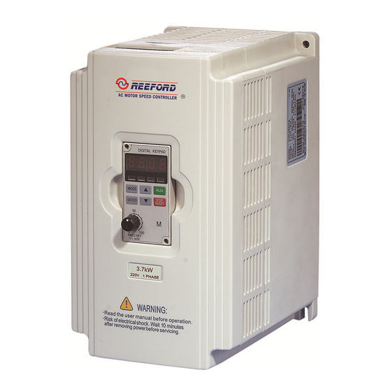
Related Manuals for Bedford B550-2001

Summary of Contents for Bedford B550-2001
- Page 1 B550 Series Sensorless Vector Frequency Drive Installation & Quick-Start Manual...
- Page 3 B550 Series sensorless vector frequency drive Preface Thank you for choosing B550 series sensorless vector frequency Drive. B550 series are manufactured by adopting high-quality components, material and incorporating the latest microprocessor technology available. Getting Started This manual will be helpful in the installation, parameter setting, troubleshooting, and daily maintenance of the AC motor drives.
-
Page 4: Table Of Contents
B550 Series sensorless vector frequency drive TABLE OF CONTENTS CHAPTER 1 RECEIVING AND INSPECTIONS 1.1 Nameplate Information ..............1-1 1.2 Model Explanation ................1-1 1.3 Serial Number Explanation ..............1-1 1.4 External Parts and Labels..............1-2 CHAPTER 2 STORAGE AND INSTALLATION 2.1 Storage .................... - Page 5 CHAPTER 6 MAINTENANCE AND INSPECTIONS 6.1 Periodic Inspection ................6-1 6.2 Periodic Maintenance ................ 6-1 CHAPTER 7 TROUBLESHOOTING AND FAULT INFORMATION ..7-1 CHAPTER 8 SUMMARY OF PARAMETER SETTING ......8-1 APPENDIX A STANDARD SPECIFICATIONS .......... A-1...
- Page 6 B550 Series sensorless vector frequency drive This page intentionally left blank.
-
Page 7: Nameplate Information
B550 Series sensorless vector frequency drive CHAPTER 1 RECEIVING AND INSPECTION This B550 series AC drive has gone through rigorous quality control tests at the factory before shipment. After receiving the AC motor drive, please check for the following: Receiving Check to make sure that the package includes an AC drive, the User Manual, and rubber bushings. -
Page 8: External Parts And Labels
B550 Series sensorless vector frequency drive 1.4 External Parts and Labels... -
Page 9: Chapter 2 Storage And Installation 2.1 Storage
B550 Series sensorless vector frequency drive CHAPTER 2 STORAGE AND INSTALLATION 2.1 Storage The AC drive should be kept in the shipping carton before installation. In order to retain the warranty coverage, the AC drive should be stored properly when it is not to be used for an extended period of time. -
Page 10: Installation
B550 Series sensorless vector frequency drive 2.3 Installation: Improper installation of the AC drive will greatly reduce its life. Be sure to observe the following precautions when selecting a mounting location. Failure to observe these precautions may void the warranty! Do not mount the AC drive near heat-radiating elements or in direct sunlight. - Page 11 B550 Series sensorless vector frequency drive CHAPTER 3 WIRING DANGER Hazardous Voltage Before accessing the AC drive: Disconnect all power to the AC drive. Wait five minutes for DC bus capacitors discharge. Any Electrical or mechanical modification to this equipment without prior written consent of Delta Electronics, Inc.
-
Page 12: Basic Wiring Diagram
B550 Series sensorless vector frequency drive 3.1 Basic Wiring Diagram Users must connect wiring according to the following circuit diagram shown below. Braking resistor (optional) Main Circuit Power AC Motor R/L1 R/L1 U/T1 S/L2 S/L2 V/T2 T/L3 T/L3 W/T3 Recommended Circuit when power supply is turned OFF by a Grounding... -
Page 13: External Wiring
B550 Series sensorless vector frequency drive 3.2 External Wiring Items Explanations Power Supply Please follow the specific power Power supply requirement shown in supply APPENDIX A. There may be inrush current during power up. Please check the chart of Fuse/NFB FUSE/NFB APPENDIX B and select the correct (Optional) -
Page 14: Control Terminal Wiring
B550 Series sensorless vector frequency drive 3.3 Control Terminal Wiring (Factory Settings) Wire Type: Copper Only Wire Type: 75 C, Copper Only Wire Gauge: 22-16 AWG Wire Gauge: 24-12 AWG Torque: 2kgf-cm (1.73 in-lbf) Torque: 4kgf-cm (3.5 in-lbf) RA RB RC M0 M1 M2 M3 M4 M5 GND AFM +10V Relay contactor... - Page 15 B550 Series sensorless vector frequency drive Terminal Terminal Function Factory Settings (NPN mode) Symbol 5A(N.O.)/3A(N.C.) 277Vac; Multi-function Relay Common 5A(N.O.)/3A(N.C.) 30Vdc Multi-function auxiliary input M0~M5-GND Multi-function input 1 Refer to P38~P42 for programming the Multi-function input 2 multi-function inputs. Multi-function input 3 ON: the activation current is 10 mA.
- Page 16 B550 Series sensorless vector frequency drive Terminal Terminal Function Factory Settings (NPN mode) Symbol Maximum: 48Vdc, 50mA Refer to P45 for programming. Max: 48Vdc/50mA MO1-DCM Multi-function Output Terminal (Photocoupler) Internal Circuit Multi-function Output Common Common for Multi-function Outputs (Photocoupler) Note: Use twisted-shielded, twisted-pair or shielded-lead wires for the control signal wiring. It is recommended to run all signal wiring in a separate steel conduit.
-
Page 17: Main Circuit Wiring
Wire Max. Torque Gauge Current Model Name kgf-cm (input / (in-lbf) output) B550-20R5(1-phase) 6.3A/2.5A 3.2A/2.5A B550-2T0R5(3-phase) 12-14 (12) (3.3-2.1) 11.5A/5.0A B550-2001(1-phase) VFD007M21B(3-phase) 6.3A/5.0A VFD015M21B(1-phase) 15.7A/7.0A 12 (3.3) 12-14 VFD015M21B(3-phase) 9.0A/7.0A (3.3-2.1) VFD022M21A(1-phase) 27A/10A 8 (8.4) 8-12 VFD022M21A(3-phase) 15A/10A (8.4-3.3) (13) -
Page 18: Wiring Notes
B550 Series sensorless vector frequency drive Terminal Explanations Terminal Symbol Explanation of Terminal Function R/L1, S/L2, T/L3 AC line input terminals (three phase) U/T1, V/T2, W/T3 Motor connections B1 – B2 Connections for Braking Resistor (optional) Earth Ground 3.5 Wiring Notes: PLEASE READ PRIOR TO INSTALLATION. CAUTION: Do not connect the AC power to the U/T1, V/T2, W/T3 terminals, as it will damage the AC drive. -
Page 19: Motor Operation Precautions
B550 Series sensorless vector frequency drive 9. Make sure that the power source is capable of supplying the correct voltage and required current to the AC drive. 10. Do not attach or remove wiring when power is applied to the AC drive. 11. - Page 20 B550 Series sensorless vector frequency drive This page intentionally left blank.
-
Page 21: Chapter 4 Digital Keypad Operation 4.1 Description Of Digital Keypad
B550 Series sensorless vector frequency drive CHAPTER 4 DIGITAL KEYPAD OPERATION 4.1 Description of Digital Keypad The digital keypad includes two parts: Display panel and keypad. The display panel provides the parameter display and shows the operation status of the AC drive and the keypad provides programming and control interface. - Page 22 B550 Series sensorless vector frequency drive Function / Program Pressing the “mode” key repetitively displays the AC drive status such as the MODE reference frequency, output frequency, and output current. Enter ENTER Pressing the “ENTER” key will store or display parameter settings. Starts AC drive operation.
- Page 23 B550 Series sensorless vector frequency drive 4.3 Explanations of Display Messages Displayed Message Descriptions The AC drives Master Frequency. The Actual Operation Frequency present at terminals U, V, and W. The custom unit (v), where v = H x Pr.-65. The counter value (c).
- Page 24 B550 Series sensorless vector frequency drive 4.4 Explanation of Digital Keypad LC-M02E Operation To view parameters: Indication after Parameter values Output frequency power on Output current FWD/REV monitor setting monitor Press Press Press Press Press Display the freq. setting monitor. Parameter value setting: Indication after Parameter setting...
- Page 25 B550 Series sensorless vector frequency drive To change frequency, proceed as follows: Note: The Pr.00 has to be set to d00 in order to operate via digital keypad. Freq. value Increasing freq. Frequency setting Freq. set at Decreasing freq. setting monitor value to 60.0 Hz.
- Page 26 B550 Series sensorless vector frequency drive This page intentionally left blank.
-
Page 27: Chapter 5 Description Of Parameter Settings
B550 Series sensorless vector frequency drive CHAPTER 5 DESCRIPTION OF PARAMETER SETTINGS : The parameter can be set during operation. Pr.00 Source of Frequency Command Factory Setting: 00 Settings 00 Master Frequency determined by digital keypad. (LC-M02E) 01 Master frequency determined by 0 to +10 V input 02 Master frequency determined by 4 to 20mA input 03 Master frequency determined by RS-485 Communication port Master frequency determined by potentiometer on digital keypad. - Page 28 B550 Series sensorless vector frequency drive Coast: The AC drive will stop the output instantly, and the motor will coast to stop. Freq. Freq. Motor Motor Speed Speed Time Time Stops according Free running to deceleration to stop time Operation command Coast Ramp...
- Page 29 B550 Series sensorless vector frequency drive This parameter determines the Maximum Output Voltage of the AC drive. The Maximum Output Voltage setting must be smaller than or equal to the rated voltage of the motor as indicated on the motor nameplate. Setting of Pr.05 must be equal to or greater than setting of Mid-Point Voltage (Pr.07).
- Page 30 B550 Series sensorless vector frequency drive Voltage Pr.05 Pr.07 Pr.09 Frequency Pr.06 Pr.03 Pr.08 Pr.04 Voltage Pr.05 Pr.07 Pr.09 Frequency Pr.08 Pr.06 Pr.04 Pr.03 Custom V/F Curve Voltage Pr.05 Pr.07 Pr.09 Frequency Pr.06 Pr.04 Pr.08 Pr.03 Fan/Pump V/F Curve...
- Page 31 B550 Series sensorless vector frequency drive Commonly used V/F Setting (1) General Purpose Factory Settings Motor Spec. 60Hz Motor Spec. 50Hz Set value Set value 60.0 Pr.03 Pr.03 50.0 60.0 Pr.04 50.0 Pr.04 220.0 Pr.05 Pr.05 220.0 Pr.06 Pr.06 10.0 Pr.07 Pr.07 12.0...
- Page 32 B550 Series sensorless vector frequency drive Pr.10. This parameter is used to determine the time required for the AC drive to ramp from 0 Hz to its Maximum Output Frequency (Pr.03). The rate is linear unless the S-Curve (Pr.14) is “Enabled”. Pr.11.
- Page 33 B550 Series sensorless vector frequency drive Freq. Acceleration/Deceleration characteristics (1), (2) Disabling S curve (3), (4) Enabling S curve Pr.15 Jog Accel / Decel Time Factory Setting: 1.0 sec Settings 0.1 to 600.0 sec or 0.01 to 600.0 sec Unit: 0.1 or 0.01 sec This parameter sets the acceleration or deceleration time for Jog operation.
- Page 34 B550 Series sensorless vector frequency drive Frequency Freq. Pr.16 Time Pr. 15 Pr. 15 Deceleration Time Acceleration Time Jog operation command Pr.17 1st Step Speed Frequency Factory Setting: 0.00 Hz Pr.18 2nd Step Speed Frequency Factory Setting: 0.00 Hz Pr.19 3rd Step Speed Frequency Factory Setting: 0.00 Hz Pr.20...
- Page 35 B550 Series sensorless vector frequency drive Pr.25 Over–Voltage Stall Prevention Settings 115V/230V series 330-450Vdc Factory Setting: 390 460V series 660-900Vdc Factory Setting: 780 575V series 825-1025Vdc Factory Setting: 975 00 disable During deceleration, the DC bus voltage may exceed its maximum allowable value due to motor regeneration.
- Page 36 B550 Series sensorless vector frequency drive During a steady-state operation with the motor load rapidly increasing, the AC drive output current may exceed the limit specified in Pr.27. When this occurs, the output frequency will decrease to maintain a constant motor speed. The drive will accelerate to the steady-state output frequency only when the output current drops below the setting for Pr.27.
- Page 37 B550 Series sensorless vector frequency drive Pr.31 Start-Point for DC Braking Factory Setting: 0.00 Settings 0.00 to 60.00Hz Unit: 0.1sec This parameter sets the frequency at which the DC Braking will begin during deceleration. Master Frequency Start-point Min. output for DC Freq.
- Page 38 B550 Series sensorless vector frequency drive Pr.34 Base-Block Time for Speed Search Factory Setting: 0.5 sec Settings 0.3 to 5.0 sec Unit: 0.1sec When a momentary power loss is detected, the AC drive will stop its output and will wait during a specified time interval called Base Block (entered in Pr.34) before resuming operation.
- Page 39 B550 Series sensorless vector frequency drive Pr.37 Lower Bound of Output Frequency Factory Setting: 0 Hz Settings 0.00 Hz to 400.0 Hz Unit: 0.1Hz Setting of this parameter must be equal to or less than the Upper Bound of Output Frequency If the Lower Bound of Output Frequency is 10Hz, and the Minimum Output Frequency (Pr.08) is set at 1.0Hz, then any command frequency between 1-10Hz will generate a...
- Page 40 B550 Series sensorless vector frequency drive 01: Two wire operation: Only Pr.38 can be set to “1”. RUN/STOP M0 "Open": Stop, "Close": Run M1 "Open": FWD, "Close":REV REV/FWD Note: Multi-function Input Terminal M0 does not have its own parameter designation. M0 must be used in conjunction with M1 to operate two and three wire control.
- Page 41 B550 Series sensorless vector frequency drive Value Function Value Function Multi-Step Speed Command 3 Jog Operation First or Second Accel/Decel Time Accel/Decel Speed Inhibit Selection External Base Block (N.O.) External Base Block (N.C.) (Normally Open Contact Input) (Normally Close Contact Input) Increase Master Frequency Decrease Master Frequency Run PLC Program...
- Page 42 B550 Series sensorless vector frequency drive 05 External Reset: Parameter value 5 programs Multi-Function Input Terminals: M1 (Pr.38), M2 (Pr.39), M3 (Pr.40), M4 (Pr.41) or M5 (Pr.42) to be an External Reset. RESET Mx "Close": Operation avalilable setting by 5 Note: the External Reset has the same function as the Reset key on the Digital keypad.
- Page 43 B550 Series sensorless vector frequency drive 09 Jog Operation Control: Parameter value 09 programs Multi-Function Input Terminal: M1 (Pr.38), M2 (Pr.39), M3 (Pr.40), M4 (Pr.41) or M5 (Pr.42) for Jog control. Mx "Close": Operation available 9 jog operation command Note: Jog operation programmed by 9 can only be initiated while the motor is stop. (Refer to Pr.15, Pr.16.) 10 Accel/Decel Speed Inhibit: Parameter value 10 programs Multi-Function Input Terminal: M1 (Pr.38), M2 (Pr.39), M3...
- Page 44 B550 Series sensorless vector frequency drive Frequency Master Frequency Pr.13 Pr.10 Pr.11 Pr.12 Pr.13 Pr.10 Decel Accel Accel/ Accel/ Decel Decel Time Mx-GND operation command 12, 13 External Base Block: Parameter values 12, 13 program Multi-Function Input Terminals: M1 (Pr.38), M2 (Pr.39), M3 (Pr.40), M4 (Pr.41) or M5 (Pr.42) for external Base Block control.
- Page 45 B550 Series sensorless vector frequency drive 14, 15 Increase/Decrease Master Frequency: Parameter values 14, 15 program the Multi-Function Input Terminals: M1 (Pr.38), M2 (Pr.39), M3 (Pr.40), M4 (Pr.41) or M5 (Pr.42) to incrementally increase/ decrease the Master Frequency each time an input is received. Mx "Close": Freq.
- Page 46 B550 Series sensorless vector frequency drive Note: The Counter Trigger input can be connected to an external Pulse Signal Generator when counting a process step or unit of material. See the diagram below. Indication value (Pr.64=1) Counter trigger signal Multi-function input terminal (Pr.38 to Pr.42 =18) The trigger timing (Pr.97=3)
- Page 47 B550 Series sensorless vector frequency drive 25 Parameter Lock (Write disable, Read is always 0) This function will disable the write function and all the content of read are 0. The application is for customer having a key to control the operator to modify parameters or modify the parameter by improper use.
- Page 48 B550 Series sensorless vector frequency drive This parameter selects if the Output Frequency, Current, PID feedback or Output Power will be the output signal on the AFM terminal (0 to 10V). Pr.44 Analog Output Gain Factory Setting: 100 Settings 00 to 200% Unit: 1% This parameter sets the voltage range of the analog output signal on output terminal AFM.
- Page 49 B550 Series sensorless vector frequency drive Function Table List: Setting Functions Setting Functions AC Drive Operational Top Count Value Attained Maximum Output Frequency Preliminary Counter Value Attained Attained Warning (PID feedback loss, Zero speed communication error) Over-Torque detection Below the Desired Frequency Base-Block (B.B.) Indication PID supervision Low-Voltage Indication...
- Page 50 B550 Series sensorless vector frequency drive PLC Program Running: terminal output is activated when the PLC program is running. PLC Program Step Completed: terminal output is activated for 0.5 sec. when each multi-step speed is attained. PLC Program completed: terminal output is activated for 0.5 sec. when the PLC program cycle has completed.
- Page 51 B550 Series sensorless vector frequency drive Power source AC/DC Multi-function indication Faults indication. output terminals. Power indication. AC 250V 2A DC 30V 2A Multi-function PHC Plus terminals output terminals. Power 48VDC 50mA Pre-set freq. attained 480VDC 50mA Minus terminal Pr.47 Desired Frequency Attained Factory Setting: 0.00 Settings 0.00 to 400.0 Hz...
- Page 52 B550 Series sensorless vector frequency drive Pr.49 Potentiometer Bias Polarity Factory Setting: 00 Settings Positive Bias Negative Bias This parameter sets the potentiometer Bias Frequency to be positive or negative. Pr.50 Potentiometer Frequency Gain Factory Setting: 100.0 Settings 0.10 to 200.0% Unit: 1% This parameter sets the ratio of analog input vs frequency output.
- Page 53 B550 Series sensorless vector frequency drive Max. Output Pr.03 Freq. 60Hz Factory Settings Pr.03=60Hz--Max. output Freq. Pr.48=16.7%-- bias adjustment Pr.49=0 -- bias polarity Pr.50=100% -- pot. freq. gain It is 10Hz 60Hz Pr.51=0 -- REV motion disable in Bias in this negative bias Adjustment range.
- Page 54 B550 Series sensorless vector frequency drive Example 5: In this example, a 6 Hz (10% of 60 Hz) negative bias is used. This setting is used to provide a noise margin (1V in this example) in noisy environments. Note that the top frequency is reduced to 54 Hz.
- Page 55 B550 Series sensorless vector frequency drive Example 8: This example shows how to set up the “anti-slope”, which is an inversely proportional variation of frequency to the input analog signal, required for some applications in process control. A sensor will generate a large signal (such as 20mA or 10V) and the AC Drive will slow or stop. Max.
- Page 56 B550 Series sensorless vector frequency drive This parameter can be used to compensate motor slip. Although no linear, it typically adds 6 Hz for a setting of 10 if Pr.03=60 Hz. When the output current of the AC drive is greater than the motor no-load current (Pr.53), the AC drive will adjust its output frequency according to this parameter.
- Page 57 B550 Series sensorless vector frequency drive Pr.60 Over-Torque Detection Mode Factory Setting: 00 Settings Over-Torque detection disabled. Enabled during constant speed operation until the allowable time for detection (Pr.62) elapses. Enabled during constant speed operation and halted after detection. Enabled during acceleration until the allowable time for detection (Pr.62) elapses.
- Page 58 B550 Series sensorless vector frequency drive PV (i) Displays the value of the internal counter (c) Displays the setting Frequency (F) Displays the parameter setting (P) Reserved Output Current (A) Display program operation (0. xxx), Fwd, or Rev The parameter can be set to display the user-defined value. (where v = H x Pr.65 Pr.65 Coefficient K...
- Page 59 B550 Series sensorless vector frequency drive This parameter defines the Master Frequency when the AC drive is controlled by the communication interface. Pr.67 Skip Frequency 1 Factory Setting: 0.00 Pr.68 Skip Frequency 2 Factory Setting: 0.00 Pr.69 Skip Frequency 3 Factory Setting: 0.00 Settings 0.00 to 400.0 Hz Unit: 0.1 Hz...
- Page 60 B550 Series sensorless vector frequency drive The parameter defines the carrier frequency of the PWM (Pulse-Width Modulated) output. Electromagnetic Carrier Frequency Acoustic Noise Heat Dissipation Noise, Leakage Current 1KHz Significant Minimal Minimal Minimal Significant Significant 15KHz From the above table, we see that the carrier frequency of PWM output has a significant influence on the electromagnetic noise, heat dissipation of the AC drive, and the acoustic noise to the motor.
- Page 61 B550 Series sensorless vector frequency drive Over-current during acceleration (OCA) Over-current during deceleration (OCd) Over-current during steady state operation (OCn) Ground fault or fuse failure (GFF) Low voltage (not record) 3 Phase Input Power Loss CPU Failure (CF2) External Base-Block (bb) Overload 2 (oL2) Auto Adjustable accel/decel failure (cFA) Software protection code (codE)
- Page 62 B550 Series sensorless vector frequency drive Continuously execute program cycles step by step (separated by “STOP”) This M drive can be programmed to execute a sequence of operations named “PLC mode”. The PLC program can be used in lieu of any external controls, relays or switches. The AC drive will change speeds and directions according to the user’s desired programming.
- Page 63 B550 Series sensorless vector frequency drive Note: The above diagram shows one complete PLC cycle. To restart the cycle, turn the PLC Program input off and then back on. Example 2 (Pr.78 = 02) Continuously executes program cycles: The diagram below shows the PLC program stepping through each speed and then automatically starting again.
- Page 64 B550 Series sensorless vector frequency drive Example 4 (Pr.78 = 04) Continuously executes program cycles step by step: In this explanation, the PLC program runs continuously step by step. Also shown are examples of steps in the reserve direction. Note: operating time for each step is 10 times Frequency the settings of Pr.81 to Pr.87.
- Page 65 B550 Series sensorless vector frequency drive Application Note: PLC program execution will be interrupted when values for JOG parameters 15 and 16 are changed. PLC Forward/Reverse Motion Factory Setting: 00 Pr.79 Settings 00 to 127 This parameter determines the direction of motion for the multi-speed Pr.17 to Pr.23 and Master Frequency.
- Page 66 B550 Series sensorless vector frequency drive 115V series 230V series 0.75 0.75 0.25 Model Number (Pr.80) Rated Output Current (A) Max. Carrier 15kHz Frequency (kHz) 460V series 575V series 0.75 7.5 0.75 Model Number (Pr.80) Rated Output 12.2 Current (A) Max.
- Page 67 B550 Series sensorless vector frequency drive Pr.89 Transmission Speed (Baud rate) Factory Setting: 01 Settings 4800 bps 9600 bps 19200 bps 38400 bps This parameter sets the transmission speed for communication on the RS-485 serial port Pr.90 Transmission Fault Treatment Factory Setting: 03 Settings Warn and Continue Operating...
- Page 68 B550 Series sensorless vector frequency drive Either ASCII or RTU Modbus protocols are used for communication. Users can select the desired mode along through parameters Pr.92 and Pr.113. Each B550 AC drive has a pre-assigned communication address specified by Pr.88. The master controller communicates with each AC drive according to its particular address.
- Page 69 B550 Series sensorless vector frequency drive 2.2 11-bit character frame (For 8-bit character): ( 8.N.2:Pr.92=3) Start Stop Stop 8-data bits 11-bits character frame ( 8.E.1:Pr.92=4) Even Stop Start parity 8-data bits 11-bits character frame ( 8.O.1:Pr.92=5) Start Stop parity 8-data bits 11-bits character frame 3.
- Page 70 B550 Series sensorless vector frequency drive ADR (Communication Address) Valid communication addresses are in the range of 0 to 254. An address equals to 0 means a broadcast to all AC drives (AMD) in the network. In this case, the AMD will not reply to the master device.
- Page 71 B550 Series sensorless vector frequency drive RTU mode: Command message: Response message: Starting data Number of data address (count by byte) Number of data Content of data (count by word) address 2102H CRC CHK Low Content of data CRC CHK High address 2103H CRC CHK Low CRC CHK High...
- Page 72 B550 Series sensorless vector frequency drive Command code: 10H, write multiple data to registers For example, set the multi-step speed, Pr.17=50.00 (1388H), Pr.18=40.00 (0FA0H). AC drive address is 01H. ASCII Mode: Command message: Response message: ‘:’ ‘:’ ADR 1 ‘0’ ADR 1 ‘0’...
- Page 73 B550 Series sensorless vector frequency drive CRC Check Low CRC Check High CHK (check sum) ASCII mode: LRC (Longitudinal Redundancy Check) is calculated by summing up, module 256, the values of the bytes from ADR1 to last data character then calculating the hexadecimal representation of the 2’s-complement negation of the sum.
- Page 74 B550 Series sensorless vector frequency drive Step 5: Repeat step 3 and 4 until eight shifts have been performed. When this is done, a complete 8-bit byte will have been processed. Step 6: Repeat steps 2 to 5 for the next 8-bit byte of the command message. Continue doing this until all bytes have been processed.
- Page 75 B550 Series sensorless vector frequency drive Address Content Functions 00: No function 01: Stop Bit 0-1 10: Run 11: Jog + Run Bit 2-3 Reserved 2000H 00: No function Command 01: FWD Bit 4-5 Read/Write 10: REV 11: Change direction Bit 6-15 Reserved 2001H Freq.
- Page 76 B550 Series sensorless vector frequency drive Address Content Functions Bit 5-7 Reserved Bit 8 1: Main freq. Controlled by communication Bit 9 1: Main freq. Controlled by external terminal Bit 10 1: Operation command controlled by communication Bit 11 1: Parameters have been locked Bit 12 0: Stop 1: Run Bit 13 1: Jog command...
- Page 77 B550 Series sensorless vector frequency drive #define RDR 0x0000 #define BRDL 0x0000 #define IER 0x0001 #define BRDH 0x0001 #define LCR 0x0003 #define MCR 0x0004 #define LSR 0x0005 #define MSR 0x0006 unsigned char rdat[60]; /* read 2 data from address 2102H of AC drive with address 1 */ unsigned char tdat[60]={':','0','1','0','3','2','1','0',’2', '0','0','0','2','D','7','\r','\n'};...
- Page 78 B550 Series sensorless vector frequency drive Accel 1 to Accel 2 Frequency Transition Factory Setting: 0.00 Pr.93 Decel 1 to Decel 2 Frequency Transition Factory Setting: 0.00 Pr.94 Settings 0.01 to 400.0 Hz Unit: 0.10 Hz 0.00 disable These functions are used to change acceleration or deceleration depending on attained frequency and not by closing contacts on the external terminals.
- Page 79 B550 Series sensorless vector frequency drive Pr.97 Preset Count Down Completion Factory Setting: 00 Settings 00 to 9999 This parameter sets a preliminary count value for the internal counter. Counter is incremented by a low-to-high transition on one of the programmed Multi-Function Input Terminals: M1 or M2 (see Pr.44 or Pr.45, setting 14).
- Page 80 If this parameter is set to 04, Accel/Decel time will be equal to or more than parameter Pr.10 ~Pr.13. This parameter should not be used when a braking unit is installed. Pr.102 Auto Voltage Regulation (AVR) Factory Setting: 00 Settings AVR function enabled AVR function disabled AVR function disabled when stop...
- Page 81 B550 Series sensorless vector frequency drive Pr.106 Rated Slip Factory Setting: 3.0 Settings 0.00 to 10.00 Hz Unit: 0.01Hz Example of Slip calculation: The rated speed of 4 poles/3 φ/ 60Hz/ 220V on the nameplate is 1710RPM. The rated slip is then: 60-(1710/(120/P))=3Hz. (being P the number of poles) Pr.107 Vector Voltage Filter...
- Page 82 B550 Series sensorless vector frequency drive Pr.112 External Terminal Scanning Time Factory Setting: 01 Settings 01 to 20 Unit: 2msec This function screens the signal on I/O terminals for CPU malfunctions due to external transients. A setting of 02, makes the scanning time to be 2 x 2 = 4 msec. Set Pr.77 to 02 before changing settings in Pr.112.
- Page 83 B550 Series sensorless vector frequency drive Limit of PID Upper Bound One Time Frequency Targeted Output of Integral Delay Command value Frequency Pr.117 Pr.118 Pr.121 Value Pr.122 Pr.120 Pr.119 Definition of Selection of Detection Value Detection value AVI( Pr.128~Pr.130 Pr.116 ACI( Pr.131~Pr.133 Pr.135...
- Page 84 B550 Series sensorless vector frequency drive Pr. 119 Differential Time (D) Factory Setting: 0.00 Settings 0.00 to 1.00 sec Unit: 0.01sec This parameter determines the damping effect for the PID feedback loop. If the differential time is long, any oscillation will quickly subside. If the differential time is short, the oscillation will subside slowly.
- Page 85 B550 Series sensorless vector frequency drive Pr. 122 PID Frequency Output Command limit Factory Setting: 00 Settings 00 to 110 % This parameter sets a limit of the PID Command frequency. If this parameter is set to 20%, then the maximum output frequency for the PID operation will be (20% x Pr.01-00). Pr.
- Page 86 B550 Series sensorless vector frequency drive This parameter is used to set the AVI input voltage that corresponds to minimum frequency. Pr. 129 Maximum Reference Value Factory Setting: 10.0 Settings 0.0 to 10.0 V This parameter is used to set the AVI input voltage that corresponds to maximum frequency.
- Page 87 B550 Series sensorless vector frequency drive Pr. 134 Analog Input Delay Filter for Set Point Factory Setting: 50 Settings 00 to 9999 Unit: 2ms Pr. 135 Analog Input Delay Filter for Feedback Signal Factory Setting: 5 Settings 00 to 9999 Unit: 2ms These two parameters are used to set the analog input delay filter in set point or feedback signal.
- Page 88 B550 Series sensorless vector frequency drive Pr. 140 External Up/Down Selection Factory Setting: 00 Settings Fixed Mode (keypad) By Accel or Decel Time Reserved This parameter is used to change the Master Frequency externally with the Multifuction Input Terminals. If any two parameters in the group Pr.39-Pr.42 are set to 14 and 15, and Pr.140 is set to 01, the up/down frequency operation is initiated as the contact closes and according to the time of acceleration/deceleration.
- Page 89 B550 Series sensorless vector frequency drive Pr. 144 Accumulative Motor Operation Day Read Only Settings 00-65535 Days Pr. 145 Accumulative Motor Operation Time (Min.) Read Only Settings 00-1440 Minutes These parameters display accumulative time of motor operation. They will not reset to zero due to parameter reset to factory and will not re-calculate if the 65535 days limit is exceeded.
- Page 90 B550 Series sensorless vector frequency drive Example: Pr. 152 Skip Frequency Width Factory Setting: 0.00 Settings 0.00 to 400.00Hz Pr. 153 Bias Frequency Width Factory Setting: 0.00 Settings 0.00 to 400.00Hz Frequency of Δ top point F = master frequency F + Pr.152 + Pr.153. Frequency of Δ...
- Page 91 B550 Series sensorless vector frequency drive Pr. 154 Reserved Pr.155 Compensation Coefficient for Motor Instability Factory Setting: 0.0 Settings 0.1 to 5.0 (recommended setting 2.0) 0.0 Disable This parameter is used to improve a condition of unstable current in any specific area. For higher frequencies, you can adjust this parameter to 0.0, and increase the setting value in Pr.155 for 30HP and above (a setting of 2.0 is recommended).
- Page 92 B550 Series sensorless vector frequency drive This page intentionally left blank.
-
Page 93: Periodic Inspection
B550 Series sensorless vector frequency drive CHAPTER 6 MAINTENANCE AND INSPECTIONS Modern AC drives are based on solid state electronics technology. Preventive maintenance is required to operate this AC drive in its optimal condition, and to ensure a long life. It is recommended to perform a monthly check-up of the AC drive by a qualified technician. - Page 94 B550 Series sensorless vector frequency drive This page intentionally left blank.
-
Page 95: Chapter 7 Troubleshooting And Fault Information
B550 Series sensorless vector frequency drive CHAPTER 7 TROUBLESHOOTING AND FAULT INFORMATION The AC drive has a comprehensive fault diagnostic system that includes several different alarms and fault messages. Once a fault is detected, the corresponding protective functions will be activated. The following faults are displayed as shown on the AC drive digital keypad display. - Page 96 B550 Series sensorless vector frequency drive Fault Fault Descriptions Corrective Actions Name 1. Ensure that the ambient temperature falls within the specified temperature range. 2. Make sure that the ventilation holes are not obstructed. The AC drive temperature 3. Remove any foreign objects on the heat sensor detects excessive heat.
- Page 97 B550 Series sensorless vector frequency drive Fault Fault Descriptions Corrective Actions Name Over-current during 1. Check for possible poor insulation at the acceleration: output line. 1. Short-circuit at motor output. 2. Decrease the torque boost setting in Pr.54. 2. Torque boost too high. 3.
- Page 98 B550 Series sensorless vector frequency drive Fault Fault Descriptions Corrective Actions Name Ground fault : The AC drive output is abnormal. When the output Ground fault : terminal is grounded (short 1. Check whether the IGBT power module is circuit current is 50% more than damaged.
- Page 99 B550 Series sensorless vector frequency drive Fault Fault Descriptions Corrective Actions Name U-phase error Return to the factory. W-phase error Phase Loss Check input phase wiring for loose contacts. Software protection failure Return to the factory. 1. Check parameter settings (Pr.116) and AVI/ACI wiring.
- Page 100 B550 Series sensorless vector frequency drive This page intentionally left blank.
- Page 101 B550 Series sensorless vector frequency drive CHAPTER 8 SUMMARY OF PARAMETER SETTINGS : The parameter can be set during operation Factory Explanation Settings Parameter Customer Setting 00: Master frequency determined by digital keypad (LC-M02E) 01: Master frequency determined by 0 to +10 V input on AVI terminal with jumpers Source of...
- Page 102 B550 Series sensorless vector frequency drive Factory Explanation Settings Parameter Customer Setting 115V/230V: 0.1 to 255.0V 10.0 Minimum Output 20.0 Pr.09 460V: 0.1 to 510.0V Voltage 26.1 575V: 0.1 to 637.0V Pr.10 Acceleration Time 1 0.1 to 600.0 sec or 0.01 to 600.0 sec 10.0 Pr.11 Deceleration Time 1...
- Page 103 B550 Series sensorless vector frequency drive Factory Explanation Settings Parameter Customer Setting 00: Stop operation after momentary power loss 01: Continues after momentary power Momentary Power loss, speed search starts with Master Pr.32 Loss Operation Frequency Selection 02: Continues after momentary power loss, speed search starts with Minimum output Frequency Maximum Allowable...
- Page 104 B550 Series sensorless vector frequency drive Factory Explanation Settings Parameter Customer Setting 20: No function 21: RESET command (N.C) 22: Control source: External Terminal 23: Control source: Keypad 24: Control source: Communication 25: Parameter Lock (Write disable, Read is always 0) 26: PID Disable (N.O.) 27: PID Disable (N.C.) 28: Second Source for Frequency...
- Page 105 B550 Series sensorless vector frequency drive Factory Explanation Settings Parameter Customer Setting 21: Over Voltage stall supervision 22: Forward command 23: Reverse command 24: Zero Speed (Includes Drive Stop) Desired Frequency Pr.47 0.00 to 400.0 Hz 0.00 Attained Adjust Bias of Pr.48 0.00 to 200.0% External Input...
- Page 106 B550 Series sensorless vector frequency drive Factory Explanation Settings Parameter Customer Setting Over-Torque Pr.61 30 to 200 % Detection Level Over-Torque Pr.62 0.0 to 10.0 seconds Detection Time 00: Decelerate to 0 Hz Loss of ACI 01: Stop immediately and display "EF" Pr.63 (4-20mA) 02: Continue operation by last frequency...
- Page 107 B550 Series sensorless vector frequency drive Factory Explanation Settings Parameter Customer Setting 00: No fault occurred 01: Over-current (oc) 02: Over-voltage (ov) Pr.73 Present Fault Record 03: Overheat (oH) 04: Overload (oL) 05: Overload 1 (oL1) 06: External Fault (EF) 07: CPU failure 1 (CF1) 08: CPU failure 3 (CF3) Second Most Recent...
- Page 108 B550 Series sensorless vector frequency drive Factory Explanation Settings Parameter Customer Setting Time Duration of Pr.82 00 to 9999 sec 2nd Step Speed Time Duration of 3rd Pr.83 00 to 9999 sec Step Speed Time Duration of 4th Pr.84 00 to 9999 sec Step Speed Time Duration of 5th Pr.85...
- Page 109 B550 Series sensorless vector frequency drive Factory Explanation Settings Parameter Customer Setting Total Time Count Read Pr.98 from Power On 00 to 65535 days Only (Days) Total Time Count Read Pr.99 from Power On 00 to 1440 minutes Only (Minutes) Pr.100 Software Version 00: Linear Accel/Decel...
- Page 110 B550 Series sensorless vector frequency drive Factory Explanation Settings Parameter Customer Setting 00: Fan Off when the drive stop after 1 Min. 01: AC Drive Runs and Fan On, AC Drive Cooling Pr.114 Fan Control Stops and Fan Off 02: Always Run 03: Reserved 00: Disable 01: Keypad (based on Pr.00 setting)
- Page 111 B550 Series sensorless vector frequency drive Factory Explanation Settings Parameter Customer Setting Invert Reference 00: Not inverted Pr.130 Signal AVI (0-10V) 01: Inverted Minimum Reference Pr.131 0.0 to 20.0mA Value (4-20mA) Maximum Reference Pr.132 0.0 to 20.0mA 20.0 Value (4-20mA) Invert Reference 00: Not inverted Pr.133...
- Page 112 B550 Series sensorless vector frequency drive Factory Explanation Settings Parameter Customer Setting Gear Ratio for Pr.149 Simple Index 4 to 1000 Function Index Angle for Pr.150 Simple Index 00.0 to 360.0 180.0 Function Deceleration Time Pr.151 for Simple Index 0.00 to 100.00 sec 0.00 Function Skip Frequency...
- Page 113 B550 Series sensorless vector frequency drive STANDARD SPECIFICATIONS Voltage Class 115V Class Model Number B550-XXXX Max. Applicable Motor Output 0.75 (kW) Max. Applicable Motor Output 0.25 (hp) Rated Output Capacity (kVA) Rated Output Current (A) Maximum Output Voltage (V) 3-Phase proportion to twice the input voltage Output Frequency (Hz) 0.1~400 Hz Carrier Frequency (kHz)
- Page 114 B550 Series sensorless vector frequency drive Voltage Class 460V Class 3-phase Rated Input Current (A) Rated Voltage, Frequency 3-phase 380-480 VAC, 50/60Hz ± Voltage Tolerance 10% (342~528 VAC) ± Frequency Tolerance 5% (47~63 Hz) Cooling Method Fan Cooled Weight (kg) Voltage Class 575V Class Model Number B550-6XXX...
- Page 115 B550 Series sensorless vector frequency drive Keypad Setting by Frequency External Potentiometer-5KΩ/0.5W, 0 to +10VDC, 4 to 20mA RS-485 interface; Multi-Function Setting Signal Inputs 0 to 5 (7 steps, Jog, up/down) Operation Keypad Set by RUN, STOP Setting External M0 to M5 can be combined to offer various modes of operation, RS-485 serial Signal Signal interface (MODBUS).
- Page 116 B550 Series sensorless vector frequency drive This page intentionally left blank.
Need help?
Do you have a question about the B550-2001 and is the answer not in the manual?
Questions and answers