Sign In
Upload
Manuals
Brands
Bedford Manuals
DC Drives
B550-4005
Bedford B550-4005 DC Drives Manuals
Manuals and User Guides for Bedford B550-4005 DC Drives. We have
1
Bedford B550-4005 DC Drives manual available for free PDF download: Installation And Quick Start Manual
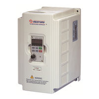
Bedford B550-4005 Installation And Quick Start Manual (117 pages)
Sensorless Vector Frequency Drive B550 Series
Brand:
Bedford
| Category:
DC Drives
| Size: 2 MB
Table of Contents
Getting Started
3
Preface
3
Table of Contents
4
Chapter 1 Receiving and Inspections
7
Model Explanation
7
Nameplate Information
7
Receiving and Inspection
7
External Parts and Labels
8
Ambient Conditions
9
CHAPTER 2 STORAGE and INSTALLATION 2.1 Storage
9
Installation
10
CHAPTER 3 Wiring
11
Asic Wiring Diagram
12
External Wiring
13
Control Terminal Wiring
14
NPN Mode
14
Main Circuit Wiring
17
Terminal Explanations
18
Wiring Notes
18
Motor Operation Precautions
19
Applicable Codes
11
General Wiring Information
11
Short Circuit Withstand
11
CHAPTER 4 DIGITAL KEYPAD OPERATION 4.1 Description of Digital Keypad
21
Explanation of the LED Indicators
22
Function / Program
22
LED Displays
22
Explanations of Display Messages
23
Explanation of Digital Keypad LC-M02E Operation
24
Parameter Value Setting
24
To Correct the Fault Messages
24
To View Parameters
24
To Change Frequency
25
To Change the Different Indication Mode as Follows
25
Chapter 5 Description of Parameter Settings
27
Source of Frequency Command
27
Source of Operation Command
27
Stop Method
27
Maximum Output Frequency
28
Maximum Output Voltage (Vmax)
28
Maximum Voltage Frequency (Base Frequency)
28
MID-Point Frequency
29
MID-Point Voltage
29
Minimum Output Frequency
29
Minimum Output Voltage
29
Custom V/F Curve
30
Fan/Pump V/F Curve
30
Standard V/F Curve
30
Commonly Used V/F Setting
31
Acceleration S-Curve
32
Acceleration/Deceleration Characteristics
33
Jog Accel / Decel Time
33
Jog Frequency
33
Over-Current Stall Prevention During Acceleration
35
Over-Current Stall Prevention During Operation
35
Over–Voltage Stall Prevention
35
DC Braking Current Level
36
DC Braking Time During Start-Up
36
DC Braking Time During Stopping
36
Maximum Allowable Power Loss Time
37
Momentary Power Loss Operation Selection
37
Start-Point for DC Braking
37
Base-Block Time for Speed Search
38
Maximum Current Level for Speed Search
38
Upper Bound of Output Frequency
38
Lower Bound of Output Frequency
39
Multi-Function Input Terminal (M0, M1)
39
Two Wire Operation
40
External Reset
42
Multi-Step Speed Command
42
Accel/Decel Speed Inhibit
43
First or Second Accel/Decel Time Selection
43
Jog Operation Control
43
External Base Block
44
Counter Trigger
45
Increase/Decrease Master Frequency
45
PLC Function Control
45
Control Source
46
Counter Reset
46
Parameter Disable
46
Analog Output Signal
47
Parameter Lock
47
PID Disable
47
Second Source of Frequency Command
47
Analog Output Gain
48
Multi-Function Output Terminal 1 (Photocoupler Output)
48
Multi-Function Output Terminal 2 (Relay Output)
48
Function Explanations
49
Function Table List
49
Adjust Bias of External Input Frequency
51
Desired Freq. Attained & Preset Freq. Attained
51
Desired Frequency Attained
51
Potentiometer Bias Polarity
52
Potentiometer Frequency Gain
52
Potentiometer Reverse Motion Enable
52
Motor No-Load Current
55
Motor Rated Current
55
Slip Compensation
55
Torque Compensation
55
Electronic Thermal Motor Overload
56
Electronic Thermal Overload Relay Selection
56
Rated Current Display of the AC Motor Drive
56
Reserved
56
Loss of ACI (4-20Ma)
57
Over-Torque Detection Level
57
Over-Torque Detection Mode
57
Over-Torque Detection Time
57
Coefficient K
58
Communication Frequency
58
PWM Carrier Frequency
59
Skip Frequency
59
Skip Frequency Band
59
Auto Restart Attempts after Fault
60
Present Fault Record
60
Second most Recent Fault Record
60
Third most Recent Fault Record
60
Parameter Lock and Configuration
61
PLC Operation Mode
61
Time for Auto Reset the Restart Times after Fault
61
Identity Code of the AC Motor Drive
65
PLC Forward/Reverse Motion
65
Communication Address
66
Time Duration of 1St Step Speed
66
Communication Protocol
67
Time out Detection
67
Transmission Fault Treatment
67
Transmission Speed (Baud Rate)
67
ASCII Mode
68
Code Meaning
68
Data Format
68
RTU Mode
68
11-Bit Character Frame
69
Communication Data Frame
69
ADR (Communication Address)
70
Command Message
70
Function (Function Code) and DATA (Data Characters)
70
Response Message
70
CHK (Check Sum)
73
Address List
74
Communication Program of PC
76
Accel 1 to Accel 2 Frequency Transition
78
Auto Energy-Saving
78
Count down Completion
78
Decel 1 to Decel 2 Frequency Transition
78
Auto Acceleration/Deceleration
79
Preset Count down Completion
79
Software Version
79
Total Time Count from Power on (Days)
79
Auto Tune Motor Parameters
80
Auto Voltage Regulation (AVR)
80
Control Mode
80
R1 Value
80
Rated Slip
81
Vector Slip Compensation Filter
81
Vector Voltage Filter
81
Voltage of Zero Speed Control
81
Cooling Fan Control
82
External Terminal Scanning Time
82
PID Set Point Selection
82
Restart Method after Fault (Oc, Ov, BB)
82
Integral Time (I)
83
PID Feedback Terminal Selection
83
Proportional Gain (P)
83
Differential Time (D)
84
Integration’s Upper Bound Frequency
84
One-Time Delay
84
PD Control
84
Feedback Signal Detection Time
85
Feedback Signal Fault Treatment
85
PID Frequency Output Command Limit
85
Source of PID Set Point
85
Invert Reference Signal AVI (0-10V)
86
Maximum Reference Value
86
Maximum Reference Value (0-20Ma)
86
Minimum Reference Value (0-20Ma)
86
Analog Input Delay Filter for Feedback Signal
87
Analog Input Delay Filter for Set Point
87
Sleep Period
87
Wake up Frequency
87
External Up/Down Selection
88
Save Frequency Set Point
88
Software Braking Level
88
Accumulative Motor Operation Day
89
Accumulative Motor Operation Time (Min.)
89
Decimal Number of Accel / Decel Time
89
Line Start Lockout
89
Bias Frequency Width
90
Skip Frequency Width
90
Communication Response Delay Time
91
Compensation Coefficient for Motor Instability
91
Maintenance and Inspections
93
Periodic Inspection
93
Periodic Maintenance
93
Chapter 7 Troubleshooting and Fault Information
95
Common Problems and Solutions
95
Summary of Parameter Settings
101
Standard Specifications
113
Advertisement
Advertisement
Related Products
Bedford B550-4001
Bedford B550-4003
Bedford B550-4002
Bedford B550-4007
Bedford B550-20R5
Bedford B550-2T001
Bedford B550-2T0R5
Bedford B550-2T002
Bedford B550-2T007
Reeford B550-2T003
Bedford Categories
Indoor Furnishing
Controller
DC Drives
Water Pump
Inverter
More Bedford Manuals
Login
Sign In
OR
Sign in with Facebook
Sign in with Google
Upload manual
Upload from disk
Upload from URL