Table of Contents
Advertisement
Advertisement
Table of Contents

Related Manuals for Velleman HAA9350


Summary of Contents for Velleman HAA9350
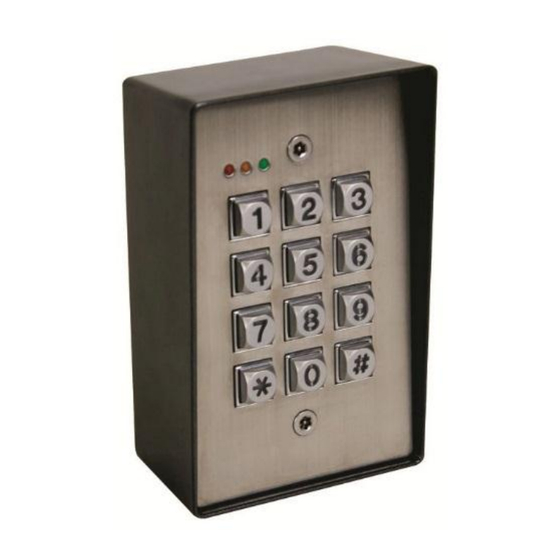
- Page 1 HAA9350 DUAL OUTPUT FULL FEATURE VANDAL-RESISTANT KEYPAD (DK-9350) USER MANUAL...
-
Page 2: Table Of Contents
TABLE OF CONTENTS INTRODUCTION ······························································································································· 3 ········································································································································ 3 ASSEMBLY ······················································ 4-6 DESCRIPTION OF CONNECTION TERMINALS & INDICATORS ················································································································· 4-6 Connec�on Terminals ························································································································· 7 The LED Indicators ·································································································································· 7 Back Ligh�ng The Pacifier Tones & The LED Indica�ng Signals ··········································································· 7 ··········································································... -
Page 3: Introduction
INTRODUCTION DK-9350 and DK-9380 are dual relay output, vandal resistant weatherproof keypads. They employ durable back-lit metal bu�on keyboard and rugged metal housing ideally for high traffic and harsh environment applica�ons. The Output 1 is a Form C relay with 5 Amp contact ra�ng mainly designed for electric door lock actua�on. -
Page 4: Description Of Connection Terminals & Indicators
DESCRIPTION OF CONNECTION TERMINALS & INDICATORS DK-9350 / DK9380 BACK-LIT JUMPER STANDARD VERSION BELL BUTTON VERSION CONNECTION TERMINALS 1 - 2 : 12-24V AC/DC -- POWER INPUT ● Connect to 12-24V AC or DC power supply. The (–) supply, Terminal (2) and (–) GND Terminal (12) are the common grounding points of the keypad system. - Page 5 9 - EG IN -- EGRESS INPUT ● A Normally Open (N.O.) input terminal refers to (–) ground, with the help of a normally open bu�on to ac�vate the Output 1 for the same �me period as like the user code. Egress bu�on is usually put inside the house near the door.
- Page 6 14 : O/P 1 INHIB. -- OUTPUT 1 INHIBIT ● A Normally Open (N.O.) input terminal refers to (–) ground. Both user code 1 and Egress bu�on can not ac�vate output 1 while this terminal is �ed to (–) ground. It is prepared for cross wire connec�on in Inter-lock applica�on.
-
Page 7: The Led Indicators
THE LED INDICATORS MAINS (AMBER) ● This is a status indicator. It flashes during standby and other indica�ons in synchroniza�on with the pacifier tones. See the chart of LED indica�on signals below for the details. DOOR (GREEN & RED) ● This is a dual LED at the right side of the panel. -
Page 8: Standard Programming Summary Chart
STANDARD PROGRAMMING SUMMARY CHART A) Enter Programming Mode with Master Code (Exit-Factory Master Code: 0 0 0 0) Entry of Master Code Confirm Comments Set system to Programming Mode NOTE: Factory has put a master code into the keypad before exit-factory, owner may take it for first �me use. - Page 9 D) Configura�on of Output Modes – Installer Programming (Default: Momentary, 1-second for all 3 outputs) Loca�on Code of Timing Confirm Comments Output 1, Momentary Mode from 1 to 999 seconds (default=1 second) 1 to 999 Output 1, Start / Stop Mode (toggle) ...
- Page 10 H) User Code Entry Modes (Auto or Manual) – Installer Programming (Default: Manual) Loca�on Func�on Codes Confirm Comments Manual Entry Mode requires to enter bu�on a�er the user codes. It is NOT necessary to set the Master Code and all User Codes in the same digit length.
-
Page 11: Setting & Programming
SETTING & PROGRAMMING Criteria for Programming (1) The keypad MUST be in Programming Mode for making Se�ng and Data Changes. (2) Programming can be accomplished in workshop or at the installa�on site. All data are stored in a non-vola�le memory and will not be lost in power off. (3) DO NOT disconnect the keypad from power while in programming mode;... -
Page 12: Programming A New Master Code
Programming A New Master Code (Loca�on 0) Loca�on New Master Code Confirm NOTE: ● Loca�on is the storage loca�on for the master code. ● The master codes can be 4-8 digits long. ● User codes must have the same length as the master code if the keypad is in auto code entry mode. -
Page 13: Programming The User Codes
Programming The User Codes (Loca�ons 1 & 2) Two groups of user codes can be programmed to operate output 1 and 2 respec�vely. The following are the programming procedures. Loca�ons User ID Entry of Code Confirm Output 1 00 - 99 4 -8 Digits ... -
Page 14: Programming The Super User Code
Programming The Super User Code (Loca�on 45) Super User Code is a mul�-task user code for ac�va�ng the two outputs 1 & 2 and opera�ng the special func�ons of Output 1. Loca�ons Super User Code Confirm 4 - 8 Digits NOTE: ●... - Page 15 2) Overriding The Door Lock Controlled by Output 1 (Keep Door Un-locked) The Output 1 is usually for door lock control. In some circumstances, the door lock may be required to be un-locked for a period for people to enter-exit the premises conveniently without user code.
-
Page 16: Programming The Duress Codes
Programming The Duress Codes (Loca�on 46) Duress Code(s) is an important code to protect the user in case of forcing to open the door under duress. The duress code operates like a normal user code to ac�vate Output 1 for door opening and at the same �me it also ac�vates the Duress Output without any indica�on. -
Page 17: Programming The Visitor Codes
Programming The Visitor Codes (Loca�on 47) Visitor Codes are temporary user codes that can be assigned to visitors or temporary workers to ac�vate Output 1 (usually for door lock actua�on). They can be programmed for One-Time use or with Time-Limit in a valid dura�on. Loca�ons User ID Valid Dura�on... -
Page 18: Dele�Ng User Codes & Other Func�On Codes
Dele�ng User Codes & Other Func�on Codes (Loca�ons 1, 2, 45, 46, & 47) To delete a user who has le� the company or who no longer has the authority to enter the protected area. Deleting Examples: 1. Set keypad to programming mode with master code and key. -
Page 19: Configura�On Of Output Modes For Outputs 1 & 2
Configura�on of Output Modes for Outputs 1 & 2 (Loca�ons 40–43 & 50–53) Outputs 1 & 2 can be programmed to trigger with the following op�ons. for a programmed length of �me from 1 to 999 seconds; or to trigger ON and OFF in toggle with a user code; or to trigger ON with an accelerated start code and OFF with an full digit user code. - Page 20 Programming Examples: 1. Set keypad to programming mode with master code and key. Taking the previous programmed master code 3 2 8 9 as example here: 2. Set Output 1 in momentary mode of 5 seconds: ...
-
Page 21: False A�Empt System Lock-Up Or Repor�Ng
False A�empt System Lock-up or Repor�ng (Loca�on 70) The keypad can be programmed to give system lock up or to report the event in order to secure the premises against unauthorized entry of mul�ple false codes are entered. The lock-up op�ons are represented by a 1 or 2 digits code for owner’s selec�on. -
Page 22: Door Forced-Open Warning & Alarm
Door Forced-Open Warning (Loca�on 80) The keypad will give door forced-open warning if the door is opened without using a user code or pressing the egress bu�on. This func�on requires an op�onal Normally Closed (N.C.) door posi�on monitoring switch on the door (usually a magne�c contact or other door protec�on switch with N.C. contact). -
Page 23: User Code Entry Modes (Auto Or Manual)
User Code Entry Modes (Auto or Manual) (Location 82) Some users like to press key to confirm a code entry manually to prevent the unauthorized person to easily check out the digit length of the user code; but some people do not. They prefer the keypad to check the code automa�cally when the last number of digit is reached. -
Page 24: Egress Delay & Warning
Egress Delay & Warning (Location 85) Most of the keypads mainly controls “Going In” with user codes and controls “Going Out” simply pressing an egress bu�on. However, in some situa�ons, providing some warning and delay are desirable before the door is open a�er pressing the egress bu�on. For example, in hospitals or schools, it may be desirable to delay the egress opera�on and provide a warning to prevent pa�ents or young children from easily leaving the protected area. -
Page 25: Delay Time To Start Door-Propped-Up Warning
NOTE: For safety and to avoid confusion, when a delay is programmed, please post a no�ce near the egress bu�on to no�fy the users. Here are two example s�ckers for an egress bu�on with 5 seconds momentary delay or 5 seconds press-and-hold delay. Press The Bu�on Momentarily Press And Hold The Bu�on And Wait For 5 Seconds... -
Page 26: Set Keypad To Single User Mode (To Whom It May Require)
SET KEYPAD TO SINGLE USER MODE (to whom it may require) This keypad also consists of a simplified version so�ware for code entry. It is single user mode for those users only need one user code for each output and execu�ng each of the special func�ons. Once the keypad is in single user mode, there is no User ID required for the codes, just simply enter the code to each Loca�ons directly. -
Page 27: Programming Examples For "Single-User Mode
2) Recording Super User Code – User Programming (No Default Codes) Loca�on Entry of Code Confirm Comments 4 digits fixed Owner’s Mul�-task User Code 3) Recording Duress Codes – User Programming (No Default Codes) Loca�on Entry of Code Confirm Comments ... -
Page 28: Specifications
SPECIFICATIONS ● Opera�on Voltage: 12-24V AC/DC, full voltage range ● Opera�on Current: Quiescent - 16mA Maximum - 78mA (Relays opera�ng) ● Opera�on Modes: a) Mul� User Mode -- 100 user codes for output 1 (user number 00-99), Auto or Manual Code Entry -- 10 user codes for output 2 (user number 0-9), Auto or Manual Code Entry b) Single User Mode -- 1 user code for each output and the special func�ons, Auto or Manual Code... -
Page 29: Application Example
APPLICATION EXAMPLES 1) BASIC WIRINGS OF A STAND ALONE DOOR LOCK 12 13 DK-9350 OR DK-9380 (−) DOOR ( + ) ( – ) OUTPUT 1 OUTPUT 2 SENS N.C. COM N.O. N.C. COM N.O. 12-24V AC/DC N.C. DOOR SENS SWITCH (OPTIONAL) OUTPUT RELAY N.O. - Page 30 2) BASIC WIRINGS FOR DOOR LOCK OPEN AND ALARM ARM-DISARM CONTROL ALARM CONTROL PANEL TAMPERPROOF N.C. TO A 24 HOUR N.C. ZONE COMMON GROUND OF KEYPAD AND ALARM SYSTEM DK-9350 OR DK-9380 N.O. DURESS -- TO A 24 HOUR N.O. ZONE N.O.
-
Page 31: Application Example
3) BASIC WIRINGS OF AN INTER-LOCK SYSTEM USING TWO KEYPADS CROSS WIRE CONNECTION FOR INTER-LOCK FUNCTIONS COMMON GROUND DK-9350 OR DK-9380 DK-9350 OR DK-9380 ( + ) ( – ) OUTPUT 1 OUTPUT 2 ( + ) ( – ) OUTPUT 1 OUTPUT 2 N.C. -
Page 32: Application Hints For The Auxiliary Facilities
APPLICATION HINTS FOR THE AUXILIARY FACILITIES 16 17 The tamper switch is Nomally Closed while the keypad is secured on gang box. It is open when the keypad is removed from the gang box. To prevent sabotage, connect these terminals in series with a 24 hour N.C. - Page 33 (D) DURESS OUTPUT The Duress Output will switch to (−) ground when duress code is entered. You may use it to turn ON an LED lamp and / or a small buzzer to notify a guard; or connect it to a 24 hour Normally Open protection zone of an alarm system.
- Page 34 (F) DOOR BELL (G) DOOR BELL ELECTRONIC DOOR CHIME The Door Bell terminal is a Normally Open The Door Bell terminal is a Normally Open relay contact with the power rating of relay contact with the power rating of DOOR BELL BUTTON 30VDC/1A.
-
Page 35: Auxiliary Information
AUXILIARY INFORMATION DRY CONTACT ● A dry contact means that no electricity is connected to it. It is prepared for free connec�ons. The Relay Output contacts provided in this keypad system are dry contacts. N.C. ● Normally Closed, the contact is closed circuit at normal status. It is open circuit when ac�ve. N.O. - Page 36 • Velleman® can decide to replace an article with an equivalent article, or to refund the retail value totally or partially when the complaint is valid and a free repair or replacement of the article is impossible, or if the expenses are out of proportion.
Need help?
Do you have a question about the HAA9350 and is the answer not in the manual?
Questions and answers