Table of Contents
Advertisement
Quick Links
120 DSP
Basic Signal Level Meter
Operation Manual
innovative technology to keep you a step ahead
Copyright © 2017 Trilithic, Inc. All Rights Reserved - 082517-REV3
www.trilithic.com
Specifications are subject to change without notice. Please contact your sales representative for further information.
Advertisement
Table of Contents

Related Manuals for Trilithic 120 DSP


Summary of Contents for Trilithic 120 DSP
- Page 1 Basic Signal Level Meter Operation Manual innovative technology to keep you a step ahead Copyright © 2017 Trilithic, Inc. All Rights Reserved - 082517-REV3 www.trilithic.com Specifications are subject to change without notice. Please contact your sales representative for further information.
- Page 2 1 20 Basic Signal Level Meter THIS PAGE LEFT INTENTIONALLY BLANK 120 DSP Operation Manual www.trilithic.com Page ii...
- Page 3 Basic Signal Level Meter Putting Innovation Within Reach Product innovation at Trilithic has always been characterized by one thing: it’s practical. It makes life easier for customers. It’s the natural result of listening to them. That philosophy has been the driving force behind the company’s growth from its beginnings as a two-man engineering team in 1986 to its current position as a global manufacturer with more than 130 employees.
- Page 4 1 20 Basic Signal Level Meter THIS PAGE LEFT INTENTIONALLY BLANK 120 DSP Operation Manual www.trilithic.com Page iv...
-
Page 5: Table Of Contents
Conventions Used in this Manual..................I-5 Precautions ..........................I-5 Recommended Software & Hardware..................I-7 ViewPoint Express ......................I-7 Chapter 2 Introduction ..........................I-9 What is the 120 DSP? ......................I-9 Overview .........................I-9 Autotest Apps........................I-9 Job Management ......................I-9 Level Measurements ....................I-10 Channel Plan Scan ...................... I-10 Spectrum Measurements .................... - Page 6 Equipment Supplied with the 120 DSP ................I-13 Replacement Parts......................I-13 Field Accessories ......................I-14 Software ..........................I-14 A Guided Tour of the 120 DSP ..................I-15 Front View ........................I-15 Rear View ........................I-16 Top View ........................I-17 Bottom View ......................... I-17 Protective Carrying Case .....................
- Page 7 Overview ..........................II-5 Version Information ......................II-6 Calibration Information ......................II-6 Network Information ......................II-7 Memory Information ......................II-7 Option Information.......................II-8 Option Activation .........................II-9 Unit ID ..........................II-9 Function Menu Options ....................II-10 Boot Parameters ......................II-10 Detect Issues .......................II-11 120 DSP Operation Manual Page TOC-3 www.trilithic.com...
- Page 8 Create a New Channel Plan ..................II-39 Open an Existing Channel Plan .................. II-40 Adding Channels to a Channel Plan ................II-41 Removing Channels from a Channel Plan..............II-41 Editing a Channel ....................... II-42 Basic Channel Settings....................II-42 120 DSP Operation Manual www.trilithic.com Page TOC-4...
- Page 9 Ethernet Settings......................II-65 Prompt User ........................ II-66 IP Mode ........................II-66 Address / Prefix ......................II-67 Subnet / Netmask ....................... II-68 Gateway / Route ......................II-69 Primary DNS ....................... II-70 Secondary DNS ......................II-71 120 DSP Operation Manual Page TOC-5 www.trilithic.com...
- Page 10 Activate USB Power ....................II-90 Deactivate USB Power ....................II-90 Chapter 5 Firmware Updates ....................... II-91 Overview .......................... II-91 Update Firmware from Website ..................II-92 Update Firmware from a USB Flash Drive ............... II-93 120 DSP Operation Manual www.trilithic.com Page TOC-6...
- Page 11 Changing Comments of an Existing Job..............III-12 Changing Comments of an Existing Job..............III-12 Chapter 3 Using Autotests ........................III-13 Overview ......................... III-13 Location Pass/Fail Indicators ..................III-15 Executing an Autotest ..................... III-16 Pass/Fail Measurement Indicators .................. III-17 120 DSP Operation Manual Page TOC-7 www.trilithic.com...
- Page 12 Modulation Type Adjustment ..................IV-23 Channel Standard Adjustment ................... IV-24 Symbol Rate Adjustment ................... IV-24 Display Type Adjustment ................... IV-25 Bar Graph ......................IV-25 QAM Constellation ....................IV-26 Equalizer Tap ......................IV-26 Bit-Error Rate ....................... IV-27 120 DSP Operation Manual www.trilithic.com Page TOC-8...
- Page 13 Text View ........................IV-51 Go to Level ........................ IV-51 Reference Level Adjustment ................... IV-52 Vertical Scale Adjustment ....................IV-52 Tilt Measurement & Marker Adjustment ................IV-53 Function Menu Options ....................IV-54 Save Data Log ......................IV-54 120 DSP Operation Manual Page TOC-9 www.trilithic.com...
- Page 14 Vertical Scale Adjustment ..................IV-81 Start Frequency Adjustment ..................IV-81 Stop Frequency Adjustment..................IV-82 Center Frequency Adjustment ................... IV-83 Span Frequency Adjustment..................IV-84 Marker Adjustment ..................... IV-85 Detector Type ......................IV-86 Maximum ......................IV-86 Average ........................ IV-86 120 DSP Operation Manual www.trilithic.com Page TOC-10...
- Page 15 Setting the ACTS Port ..................IV-104 Traceroute ....................... IV-104 Opening a Limit Set....................... IV-105 Removing a Limit Set ....................IV-106 Pass/Fail Measurement Indicators ................IV-107 Function Menu Options ....................IV-108 Save Data Log ......................IV-108 Delete Favorites......................IV-110 120 DSP Operation Manual Page TOC-11 www.trilithic.com...
- Page 16 Hum Measurement (OPTIONAL) ..................V-5 Physical Specifications....................... V-6 Available Interface Types ....................V-7 Battery & Power Specifications ..................V-7 Environmental Specifications ..................... V-8 Chapter 2 Warranty Information ......................V-9 Trilithic Broadband Instruments 1-Year Limited Warranty ..........V-9 120 DSP Operation Manual www.trilithic.com Page TOC-12...
-
Page 17: Section I: The Basics
120 DSP Basic Signal Level Meter Section I: The Basics www.trilithic.com... - Page 18 1 20 Basic Signal Level Meter THIS PAGE LEFT INTENTIONALLY BLANK 120 DSP Operation Manual www.trilithic.com Page I-2...
-
Page 19: General Information
(FAQs), bulletins and other technical information. You can also check this website for product updates. Trilithic technical support is available Monday through Friday from 8:00 AM to 5:00 PM EST. Callers in North America can dial 1-317-895-3600 or 1-800-344-2412 (toll free). International callers should dial 1-317-895-3600 or fax questions to 1-317-895-3613. -
Page 20: How This Manual Is Organized
Basic Signal Level Meter How this Manual is Organized Thank you for choosing the 120 DSP. This manual is provided with the 120 DSP to help the user become better acquainted with the device and to become productive faster. Each section is written as though the user is familiar with the basic operation of the instrument and is broken into chapters for each function. -
Page 21: Conventions Used In This Manual
DC). A larger voltage will damage the meter. Do not use the instrument in any manner not recommended by the manufacturer. A strong electromagnetic field may affect the measurement accuracy of the 120 DSP. 120 DSP Operation Manual Page I-5 www.trilithic.com... - Page 22 1 20 Basic Signal Level Meter Use only the battery charger supplied with the 120 DSP. Use of any other charger may damage the battery. Damage caused by improper cleaning of the display screen will void the warranty of the 120 DSP.
-
Page 23: Recommended Software & Hardware
Create configuration packages with channel plans, limit sets, and autotests • Define meter settings • Upload and download data to your 120 DSP via a USB flash drive • Query, display, and delete test data (optional) For the most current version of ViewPoint Express, contact... - Page 24 1 20 Basic Signal Level Meter THIS PAGE LEFT INTENTIONALLY BLANK 120 DSP Operation Manual www.trilithic.com Page I-8...
-
Page 25: Chapter 2 Introduction
Up to Six Hours of Operation from a Single Charge Autotest Apps The 120 DSP streamlines your testing procedures while making installation and troubleshooting more efficient with the use of Autotest apps. These apps allow users to perform a Return Spectrum and Channel Plan Scan of the channels included in the selected channel plan. -
Page 26: Level Measurements
Spectrum Measurements The 120 DSP comes standard with the ability to display the the full return spectrum from 4 to 110 MHz. The spectrum display provides peak measurements, color-coded markers, and delta measurements. -
Page 27: Standard Testing Features
User-Defined Autotests A significant time and cost savings feature of the 120 DSP is the capability to group tests into automatic tests that can be executed with a single keystroke. Several Autotests can be stored in the meter and recalled as needed. These may include Level, Tilt, Spectrum, Hum, and Limit tests. -
Page 28: Flexible Data Storage
With Trilithic’s complimentary ViewPoint Express PC software, you can quickly create setup files for the 120 DSP. These files can be packaged for easy transfer to one or all of your 120 DSP units simply using a standard USB flash drive. -
Page 29: Getting To Know Your 120 Dsp
USB Charge & Data Cable (Mini-B to Standard-A Male) • USB Flash Drive Adapter (Mini-B Male to Standard-A Female) Replacement Parts The following replacement parts are available for the 120 DSP: Part Number Description 0090048000 Li-ION Replacement Battery (Replacement Requires 2 Batteries) -
Page 30: Field Accessories
1 20 Basic Signal Level Meter Field Accessories The following accessories are available for the 120 DSP: Part Number Description 2071527048 Precision RF Coaxial Test Cable (I/O-15) 0610169007 CL-9 Vehicle Power Adapter with USB cable 0610169004 CL-9 Vehicle Power Adapter without USB cable... -
Page 31: A Guided Tour Of The 120 Dsp
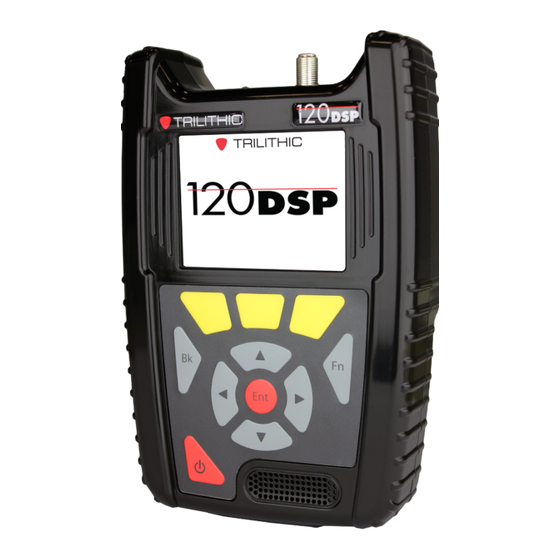
1 20 Basic Signal Level Meter A Guided Tour of the 120 DSP Front View RF Input Connector LCD Screen Soft Keys Back Button Arrow Buttons Power Button Enter Button Water Resistant Speaker Function Button 120 DSP Operation Manual Page I-15... -
Page 32: Rear View
1 20 Basic Signal Level Meter Rear View RF Input Connector Identification Label (S/N, FCC ID & Notice) 120 DSP Operation Manual www.trilithic.com Page I-16... -
Page 33: Top View
(10/100 Mbit/s) Protective Rubber Door In the image above, the protective rubber door is in the open position for illustrative purposes. This door should remain closed when not using any of these ports. 120 DSP Operation Manual Page I-17 www.trilithic.com... -
Page 34: Protective Carrying Case
1 20 Basic Signal Level Meter Protective Carrying Case The 120 DSP includes a protective carrying case with the following features: • Molded form-fit design that includes an impact resistant foam core with coated ballistic nylon finish to provide maximum protection •... -
Page 35: Cleaning The Display Screen
For correct cleaning of the display, follow these four simple steps: 1. Turn off the 120 DSP before you begin. If the screen is dark, it will be easier to see any areas that aren’t clean. -
Page 36: Battery Charging
6 hours or to trickle charge the batteries while the instrument is in use. Plug the power adapter & battery charger into the DC charge port of the 120 DSP on the bottom of the instrument under a protective cover. -
Page 37: Charging Status
Basic Signal Level Meter Charging Status The Title Bar at the top of the 120 DSP screen displays the battery voltage and the following charging status icons: Charging - This icon is displayed when the 120 DSP battery is charging. When charging, the battery voltage will be shown between 3 and 4 VDC (dependent on charging source). -
Page 38: Basic Navigation & Control
Basic Signal Level Meter Basic Navigation & Control Startup Once the instrument’s battery is charged, you may startup the 120 DSP by pressing the Power button at the bottom left of the keypad. Upon startup one of the following will occur: •... -
Page 39: Sleep Mode
Basic Signal Level Meter Sleep Mode The sleep mode is used to conserve power by putting the 120 DSP to sleep when not in use. This also allows the 120 DSP to be turned back on quickly when moving from one test... -
Page 40: Shutdown
1 20 Basic Signal Level Meter Shutdown Shutdown allows the 120 DSP to be turned off at the end of the work day to conserve power. Automatic Shutdown The 120 DSP will automatically enable the automatic shutdown mode to conserve power after the 120 DSP has been idle for a specified period of time. -
Page 41: Display Screen
DSP menus and show information when the instrument is performing tests. On the Autotest, Troubleshoot, and Setup menus, the right side of the message bar displays network connection icons to indicate which types of network connections are currently active. 120 DSP Operation Manual Page I-25 www.trilithic.com... -
Page 42: Main Display Area
If multiple user profiles are enabled, the Welcome to the 120 DSP screen will always be displayed upon startup as shown in the image to the right. -
Page 43: Softkey Labels
Spectrum Measurements - Peak Hold and Limit Set commands. • File Explorer - Database Backup/Restore, File Delete/Export, Sort by Name/Type/Date-Time/Size and Save Logs commands. • Web Browser - Back, Menu, Home and Refresh commands. 120 DSP Operation Manual Page I-27 www.trilithic.com... -
Page 44: Selecting On-Screen Items
In the example images shown to the right, notice how the currently selected item is highlighted blue and the other items remain gray. Once you select an item, you will either enter a new function or a window will appear. 120 DSP Operation Manual www.trilithic.com Page I-28... -
Page 45: Main Keypad
Function Button The Function button can be selected at any time to display a pop-up menu with additional functions. These functions vary from capturing screens for future reference to saving configuration files. 120 DSP Operation Manual Page I-29 www.trilithic.com... -
Page 46: Using The Virtual Keyboard
To delete existing text, use the Back softkey. Once you have finished making changes, select the Done softkey to save your changes and exit, or select the Back button on the keyboard to exit without saving your changes. 120 DSP Operation Manual www.trilithic.com Page I-30... -
Page 47: Chapter 4 Function Menu
This chapter will provide you with an understanding of the most common Function menu options as follows: • Pause Meter • Toggle Flashlight • Screen Capture • Network Manager • Log Off User 120 DSP Operation Manual Page I-31 www.trilithic.com... -
Page 48: Pause Meter
The Title Bar will be highlighted in red and display Paused until the pause meter function is disabled. To exit the pause meter function, Press the Back button. 120 DSP Operation Manual www.trilithic.com Page I-32... -
Page 49: Toggle Flashlight
To manually toggle the LED flash light off, Press the Function button and then select the Toggle Flashlight function again. To adjust the Flashlight Delay, see Section II: Setup, Chapter 3: Meter Configuration, Interface Settings. 120 DSP Operation Manual Page I-33 www.trilithic.com... - Page 50 Virtual Keyboard. It will then be saved to the internal memory of the 120 DSP. To view the files saved to the internal memory of the 120 DSP, see Section II: Setup, Chapter 4: File Management. 120 DSP Operation Manual www.trilithic.com...
-
Page 51: Network Manager
The Network Manager window provides controls for the following type of network connection: • Ethernet - This enables the built-in 10/100 Mbit/s Ethernet Port. 120 DSP Operation Manual Page I-35 www.trilithic.com... -
Page 52: Connection Indicators
The Continue window will appear as shown in the image to the right. Select the OK button to disconnect or select the Cancel button to exit without disconnecting. 120 DSP Operation Manual www.trilithic.com Page I-36... -
Page 53: Ethernet Connection
Ethernet Connection Perform the following steps to connect using the Ethernet connection: 1. Connect an Ethernet cable to the Ethernet Port of the 120 DSP. 2. Select the Ethernet connection button from the Network Manager window as shown in the image to the right. - Page 54 Message Bar. 6. Return to the Network Manager window to view the MAC, IP, Subnet, Gateway, and DNS of the Ethernet connection as shown in the image to the right. 120 DSP Operation Manual www.trilithic.com Page I-38...
-
Page 55: Log Off User
Log Off User button from the Function menu as shown in the image to the right. The Welcome to the 120 DSP screen will be displayed, from this screen you can now log in as a different user. -
Page 56: Www.trilithic.com Page
1 20 Basic Signal Level Meter THIS PAGE LEFT INTENTIONALLY BLANK 120 DSP Operation Manual www.trilithic.com Page I-40... -
Page 57: Section Ii: Setup Menu
120 DSP Basic Signal Level Meter Section II: Setup Menu www.trilithic.com... -
Page 58: Www.trilithic.com Page
1 20 Basic Signal Level Meter THIS PAGE LEFT INTENTIONALLY BLANK 120 DSP Operation Manual www.trilithic.com Page II-2... -
Page 59: Chapter 1 Overview
Basic Signal Level Meter Introduction Select the Setup softkey to display the Setup menu as shown in the image to the right. The 120 DSP enables you to select from numerous instrument setup functions. These functions allows you to view, edit, and adjust information and setup parameters for the meter. -
Page 60: Www.trilithic.com Page
1 20 Basic Signal Level Meter THIS PAGE LEFT INTENTIONALLY BLANK 120 DSP Operation Manual www.trilithic.com Page II-4... -
Page 61: Instrument Information
Trilithic factory and cannot be changed by the user. The serial number also appears on a label on the back side of the 120 DSP. Please provide this number when requesting an RMA for troubleshooting, service, calibration, or repair. -
Page 62: Version Information
Version Information Select the Version Information button to display details on the version of software/firmware installed in the 120 DSP. This information will be helpful if you are updating your firmware or upgrading your instrument’s option package. When you perform a firmware update, this information will be automatically updated. -
Page 63: Network Information
Select the Memory Information button to display details of the memory available and used on the 120 DSP. This information is automatically updated as files are saved and stored in the 120 DSP. 120 DSP Operation Manual Page II-7 www.trilithic.com... -
Page 64: Option Information
120 DSP. This information is automatically updated as options are added to the 120 DSP. After initial sale, most options can be simply added with the purchase of an option activation code. For more information, call your sales representative or Trilithic at 800-344-2412. -
Page 65: Option Activation
Option Activation Select the Option softkey and then enter the option activation key that you purchased from Trilithic. The dash between each four digits of the code as shown in the image to the right is not required when entering the option activation key. -
Page 66: Function Menu Options
120 DSP. The boot parameters will be displayed in the right side of the Information screen. This information is used for advanced troubleshooting by Trilithic technical support. 120 DSP Operation Manual www.trilithic.com... -
Page 67: Detect Issues
Basic Signal Level Meter Detect Issues Select the Detect Issues button to detect any file system issues of the 120 DSP. Any detected file system issues will be displayed in the right side of the Information screen. This information is used for advanced troubleshooting by Trilithic technical support. -
Page 68: Www.trilithic.com Page
1 20 Basic Signal Level Meter THIS PAGE LEFT INTENTIONALLY BLANK 120 DSP Operation Manual www.trilithic.com Page II-12... -
Page 69: Meter Configuration
Overview Select the Setup icon as shown in the image to the right to adjust the meter configuration of the 120 DSP. The Meter Configuration screen will be displayed as shown in the image to the right. This screen allows you to modify the following types of settings: •... -
Page 70: Global Settings
The Global Settings screen will be displayed as shown in the image to the right. This screen allows you to modify the global settings of the 120 DSP. From within the Global Settings screen, use the left/ right arrow buttons on the keypad to navigate through the list of setup items. -
Page 71: Operating Level
Basic Signal Level Meter Operating Level The Operator Level setting is used to control whether the 120 DSP is operating in its normal mode or in an advanced logging mode. The logging mode is used for advanced troubleshooting by Trilithic technical support. -
Page 72: Tethering Control
Basic Signal Level Meter Tethering Control The Direct to Tethered setting is used to control whether the 120 DSP automatically enters its tethered mode upon startup/login. The default setting for Direct to Tethered is No, use the up/down arrow buttons to select from the... -
Page 73: Language
1 20 Basic Signal Level Meter Language The 120 DSP can be equipped to work in various languages. The default language is English, use the up/ down arrow buttons to select from the following languages. • English • Spanish •... -
Page 74: Current Date/Time
Basic Signal Level Meter Current Date/Time The Current Date/Time setting is used to set the current date and time for the 120 DSP. This information is displayed in the Title Bar of any navigation screen and is added to every data log, measurement, job, and autotest. -
Page 75: Timezone
Basic Signal Level Meter Timezone The Timezone setting allows you to set the time zone of the 120 DSP. This is useful when using the instrument in areas that automatically adjust their local time based on Daylight Savings Time (DST). -
Page 76: User Settings
Select the User button as shown in the image to the right to adjust the user information that is associated with the currently logged in user of the 120 DSP. The User screen will be displayed as shown in the image to the right. -
Page 77: User Name
The User Name setting is used to set the user name for the user profile that is currently logged into the 120 DSP. This information is displayed on the welcome screen and is added to every data log, measurement, job, and autotest. -
Page 78: Company
The Company setting is used to set the company name for the user profile that is currently logged into the 120 DSP. This information is displayed on the welcome screen and is added to every data log, measurement, job, and autotest. -
Page 79: Tech Id
The Tech ID setting is used to set the technician ID for the user profile that is currently logged into the 120 DSP. This information is displayed on the welcome screen and is added to every data log, measurement, job, and autotest. -
Page 80: Interface Settings
Select the Interface button as shown in the image to the right to adjust the interface settings for the currently logged in user of the 120 DSP. The Interface screen will be displayed as shown in the image to the right. This screen allows you to modify the user interface settings. -
Page 81: Lcd Dimming Delay
Upon any button press, the LCD will automatically brighten and the delay timer will restart. Whenever the 120 DSP is being powered by the AC to DC power adapter & battery charger, the LCD dimming delay will be deactivated automatically. -
Page 82: Sleep Mode Delay
Quickly Press the Power button to awaken the 120 DSP from sleep mode. The sleep mode delay timer will automatically restart. Whenever the 120 DSP is being powered by the AC to DC power adapter & battery charger, the sleep mode delay will be deactivated automatically. -
Page 83: Turn Off Delay
The Turn Off Delay setting is used to conserve power by automatically turning off the device after the 120 DSP has been idle for a specified period of time. The default setting for the turn off delay is 1 Hour. -
Page 84: Flashlight Delay
The default setting for Keypad Beeps is Yes, use the up/down arrow buttons to select from the following preset values: • Select Yes to hear the keypad beeps. Select No to mute the keypad beeps. • 120 DSP Operation Manual www.trilithic.com Page II-28... -
Page 85: Keypad Delay
Use the up/down arrow buttons to change the value in 50 mSecond increments. • Press the Enter button and use the Virtual Keyboard to directly enter the keypad delay as shown in the image to the right. 120 DSP Operation Manual Page II-29 www.trilithic.com... -
Page 86: Keypad Rate
Use the up/down arrow buttons to change the value in 50 mSecond increments. • Press the Enter button and use the Virtual Keyboard to directly enter the keypad rate as shown in the image to the right. 120 DSP Operation Manual www.trilithic.com Page II-30... -
Page 87: Temperature Units
120 DSP. The default setting for Distance Units is Meters, use the up/down arrow buttons to select from the following preset values: • Feet • Meters 120 DSP Operation Manual Page II-31 www.trilithic.com... -
Page 88: Job & Workorder Id Length
The Job/Workorder ID Length setting is used to set the maximum number of characters to display for jobs and workorders on the 120 DSP. The default setting for the job and workorder ID length is 6 Characters. The character length can be set from a minimum of 6 characters up to a maximum of 32 characters. -
Page 89: Language
1 20 Basic Signal Level Meter Language The 120 DSP can be equipped to work in various languages. The default language is defined by the Global menu and shows here as Meter Default, but can be adjusted per user. Use the up/down arrow buttons to select from the following languages. -
Page 90: Measurement Settings
The Measure screen will be displayed as shown in the image to the right. This screen allows you to modify the measurement settings of the 120 DSP. From within the Measure screen, use the left/right arrow buttons on the keypad to navigate through the list of setup items. -
Page 91: Analog Noise Bandwidth
Use the up/down arrow buttons to change the value in 0.1 MHz increments. • Press the Enter button and use the Virtual Keyboard to directly enter the analog noise bandwidth as shown in the image to the right. 120 DSP Operation Manual Page II-35 www.trilithic.com... -
Page 92: Optimal Modulation
Use the up/down arrow buttons to change the value in 0.1% increments. • Press the Enter button and use the Virtual Keyboard to directly enter the optimal modulation as shown in the image to the right. 120 DSP Operation Manual www.trilithic.com Page II-36... -
Page 93: Velocity Of Propagation
The Hum Type setting is used to set the default hum type for testing. The default setting for Hum Type is 60 Hz, use the up/down arrow buttons to select from the following preset values: • 60 Hz • 50 Hz 120 DSP Operation Manual Page II-37 www.trilithic.com... -
Page 94: Channel Plan Management
ViewPoint Express. For instructions regarding setup using ViewPoint Express, please refer to the ViewPoint Express Operation Manual. From within the Channel Plan screen, use the arrow buttons on the keypad to navigate through the list of channels. 120 DSP Operation Manual www.trilithic.com Page II-38... -
Page 95: Create A New Channel Plan
Cancel button to exit without creating a new channel plan. 5. Use the Virtual Keyboard to enter the name of the new channel plan as shown in the image to the right. 120 DSP Operation Manual Page II-39 www.trilithic.com... -
Page 96: Open An Existing Channel Plan
4. Select the name of the channel plan that you would like to open. 5. The selected channel plan and its channels are displayed as shown below (right). Use the up/down arrow buttons to highlight specific channels for editing or removal. 120 DSP Operation Manual www.trilithic.com Page II-40... -
Page 97: Adding Channels To A Channel Plan
Basic Signal Level Meter Adding Channels to a Channel Plan The 120 DSP comes pre loaded with four different channel presets; NTSC, PAL G, Dig Video, and DOCSIS. Perform the following steps to add a channel to the channel plan: 1. -
Page 98: Editing A Channel
The Channel ID setting is used to number the selected channel. Press the Enter button and use the Virtual Keyboard to directly enter the channel number as shown in the image to the right. 120 DSP Operation Manual www.trilithic.com Page II-42... -
Page 99: Favorites Selection
The Channel Name setting is used to name the selected channel. Press the Enter button and use the Virtual Keyboard to directly enter the channel name as shown in the image to the right. 120 DSP Operation Manual Page II-43 www.trilithic.com... -
Page 100: Channel Type
The Channel Type setting is used to select the type of channel and available channel settings. Use the up/down arrow buttons to select from the following types of channels as shown in the images below: • Single • Analog • Digital 120 DSP Operation Manual www.trilithic.com Page II-44... -
Page 101: Single Channel Properties
Use the up/down arrow buttons to change the value in 0.050 MHz increments. • Press the Enter button and use the Virtual Keyboard to directly enter the center frequency as shown in the image to the right. 120 DSP Operation Manual Page II-45 www.trilithic.com... -
Page 102: Analog Channel Properties
Channel Standard The Channel Standard setting is used to select the analog encoding standard. Use the up/down arrow buttons to select from the following standards: • NTSC • PAL B/I/D/N/M/G/H/K • SECAM B/L/D/G/H/I/K 120 DSP Operation Manual www.trilithic.com Page II-46... -
Page 103: Center Frequency
Use the up/down arrow buttons to change the value in 0.050 MHz increments. Press the Enter button and use the • Virtual Keyboard to directly enter the center frequency as shown in the image to the right. 120 DSP Operation Manual Page II-47 www.trilithic.com... -
Page 104: Bandwidth
Use the up/down arrow buttons to change the value in 0.100 MHz increments. Press the Enter button and use the • Virtual Keyboard to directly enter the bandwidth as shown in the image to the right. 120 DSP Operation Manual www.trilithic.com Page II-48... -
Page 105: Video Frequency
Use the up/down arrow buttons to change the value in 0.050 MHz increments. Press the Enter button and use the • Virtual Keyboard to directly enter the center frequency as shown in the image to the right. 120 DSP Operation Manual Page II-49 www.trilithic.com... -
Page 106: Audio Frequency
The default setting for Scrambled is No, use the up/down arrow buttons to select from the following preset values: • Select Yes if the channel is scrambled. • Select No if the channel is not scrambled. 120 DSP Operation Manual www.trilithic.com Page II-50... -
Page 107: Digital Channel Properties
Channel Standard The Channel Standard setting is used to select the digital encoding standard. Use the up/down arrow buttons to select from the following standards: • Arbitrary • Annex A/B/C 120 DSP Operation Manual Page II-51 www.trilithic.com... -
Page 108: Center Frequency
Use the up/down arrow buttons to change the value in 0.050 MHz increments. Press the Enter button and use the • Virtual Keyboard to directly enter the center frequency as shown in the image to the right. 120 DSP Operation Manual www.trilithic.com Page II-52... -
Page 109: Bandwidth
Use the up/down arrow buttons to change the value in 0.100 MHz increments. Press the Enter button and use the • Virtual Keyboard to directly enter the bandwidth as shown in the image to the right. 120 DSP Operation Manual Page II-53 www.trilithic.com... -
Page 110: Modulation
Use the up/down arrow buttons to change the value in 0.001 MSPS increments. • Press the Enter button and use the Virtual Keyboard to directly enter the symbol rate as shown in the image to the right. 120 DSP Operation Manual www.trilithic.com Page II-54... -
Page 111: Docsis
• Select No if the channel is not a DOCSIS channel. Channel Presets The 120 DSP comes preloaded with four different channel presets. After editing custom channels, you may find it useful to save your own preset channels. Perform the following steps to save new channel presets: 1. -
Page 112: Save An Open Channel Plan
3. The channel plan will be saved to the internal memory of the 120 DSP. Save an Open Channel Plan with a New Name After editing an open channel plan, you can save the channel plan with a new name. This... -
Page 113: Limit Set Management
Limit Set Management Select the Limit Set button as shown in the image to the right to manage limit sets on the 120 DSP. Channel Plans and Limit Sets created/modified on the 120 DSP can only be used in the Troubleshooting menu. Autotests require ViewPoint Express Channel Plans and Limit Sets. -
Page 114: Create A New Limit Set
Cancel button to exit without creating a new limit set. 5. Use the Virtual Keyboard to enter the name of the new limit set as shown in the image to the right. 120 DSP Operation Manual www.trilithic.com Page II-58... -
Page 115: Open An Existing Limit Set
4. Select the name of the limit set that you would like to open. 5. The selected limit set and its thresholds are displayed as shown below (right). Use the up/down arrow buttons to highlight specific thresholds for editing or removal. 120 DSP Operation Manual Page II-59 www.trilithic.com... -
Page 116: Removing Limits From A Limit Set
Remove softkey. Knowing Your Limits When the 120 DSP performs testing versus a limit set, it immediately display the pass/fail status for each measurement criteria that you have set. To meet a minimum limit, the measured values must be equal to or greater than the minimum limit. - Page 117 Post Bit Error - This sets the maximum post error correction bit errors. • Tilt Level - This sets the minimum and maximum Tilt level. • Launch Level - This sets the minimum and maximum cable modem launch levels. 120 DSP Operation Manual Page II-61 www.trilithic.com...
- Page 118 • Lost Packets - This sets the maximum lost packet rate while performing a ping measurement. • Ping Time - This sets the maximum ping time while performing a ping measurement. 120 DSP Operation Manual www.trilithic.com Page II-62...
-
Page 119: Editing Limit(S
Use the left/right arrow buttons to highlight the threshold that you would like to change. Use the up/down arrow buttons or select the Enter button and use the Virtual Keyboard to enter the threshold. 120 DSP Operation Manual Page II-63 www.trilithic.com... -
Page 120: Save An Open Limit Set
3. Use the Virtual Keyboard to enter the new name for the limit set as shown in the image to the right. 4. The new limit set will be saved to the internal memory of the 120 DSP. 120 DSP Operation Manual www.trilithic.com Page II-64... -
Page 121: Ethernet Settings
These parameters can be set directly from your instrument or using ViewPoint Express. For instructions regarding setup using ViewPoint Express, please refer to the ViewPoint Express Operation Manual. 120 DSP Operation Manual Page II-65 www.trilithic.com... -
Page 122: Prompt User
Automatic. • Select IPv4 Static to manually enter the network settings. In this mode, all of the network settings must be manually adjusted as shown in the following sections. 120 DSP Operation Manual www.trilithic.com Page II-66... -
Page 123: Address / Prefix
Press the Enter button and the Virtual Keyboard will be displayed as shown in the image to the right. Use the Virtual Keyboard to enter the IP Address in the ###.###.###.### format. 120 DSP Operation Manual Page II-67 www.trilithic.com... -
Page 124: Subnet / Netmask
Press the Enter button and the Virtual Keyboard will be displayed as shown in the image to the right. Use the Virtual Keyboard to enter the subnet address in the ###.###.###.### format. 120 DSP Operation Manual www.trilithic.com Page II-68... -
Page 125: Gateway / Route
Press the Enter button and the Virtual Keyboard will be displayed as shown in the image to the right. Use the Virtual Keyboard to enter the gateway address in the ###.###.###.### format. 120 DSP Operation Manual Page II-69 www.trilithic.com... -
Page 126: Primary Dns
Press the Enter button and the Virtual Keyboard will be displayed as shown in the image to the right. Use the Virtual Keyboard to enter the primary DNS address in the ###.###.###.### format. 120 DSP Operation Manual www.trilithic.com Page II-70... -
Page 127: Secondary Dns
Press the Enter button and the Virtual Keyboard will be displayed as shown in the image to the right. Use the Virtual Keyboard to enter the secondary DNS address in the ###.###.###.### format. 120 DSP Operation Manual Page II-71 www.trilithic.com... -
Page 128: Www.trilithic.com Page
1 20 Basic Signal Level Meter THIS PAGE LEFT INTENTIONALLY BLANK 120 DSP Operation Manual www.trilithic.com Page II-72... -
Page 129: Chapter 4 File Management
Select the Files icon as shown in the image to the right to view the files that are stored in the internal memory of the 120 DSP. The File Explorer screen will be displayed as shown in the image to the right. This screen allows you to perform the following actions: •... -
Page 130: Database Backup
1 20 Basic Signal Level Meter Database Backup Backup to Internal Memory Perform the following steps to backup the 120 DSP database file to the internal memory of the 120 DSP: 1. Select the Database softkey. 2. From the Database pop-up menu, select the Backup button as shown in the image to the right. -
Page 131: Backup To Usb Flash Drive
Basic Signal Level Meter Backup to USB Flash Drive Perform the following steps to backup the 120 DSP database file to a USB flash drive: 1. Insert the USB flash drive adapter into the USB port of the 120 DSP 2. -
Page 132: Database Restore
Database Restore Restore from Internal Memory Perform the following steps to restore the 120 DSP database file from the internal memory of the 120 DSP: 1. Select the Database softkey. 2. From the Database pop-up menu, select the Restore button as shown in the image to the right. -
Page 133: Restore From Usb Flash Drive
Basic Signal Level Meter Restore from USB Flash Drive Perform the following steps to restore the 120 DSP database file from a USB flash drive: 1. Insert the USB flash drive adapter into the USB port of the 120 DSP. -
Page 134: Cloning Meter Settings To A New Meter
Basic Signal Level Meter Cloning Meter Settings to a New Meter Perform the following steps to clone all files from one 120 DSP to another: 1. Insert the USB flash drive adapter into the USB port of the 120 DSP. - Page 135 10. Login to an existing user or create a new user on the new meter to clone to. 11. Insert the USB flash drive adapter and USB flash drive into the USB port of the new meter to clone to. 120 DSP Operation Manual Page II-79 www.trilithic.com...
- Page 136 You will not have to export another database file unless there is additional files you want to move. 120 DSP Operation Manual www.trilithic.com Page II-80...
-
Page 137: Import Viewpoint Files From A Usb Flash Drive
Perform the following steps to import a ViewPoint package file from a USB flash drive: 1. Insert the USB flash drive adapter into the USB port of the 120 DSP. 2. Then insert a USB flash drive into the USB flash drive adapter. - Page 138 10. The Message Bar will indicate a successful import from the flash drive by displaying the text “Imported /media/sda1/<file_name>” as shown in the image to the right. 120 DSP Operation Manual www.trilithic.com Page II-82...
-
Page 139: Export A File
Perform the following steps to export a single file to a USB flash drive: 1. Insert the USB flash drive adapter into the USB port of the 120 DSP 2. Then insert a USB flash drive into the USB flash drive adapter. - Page 140 “Export /media/sda1/<file_name>” as shown in the image to the right. 9. Later when you are ready to import, you will see the file listed in the ViewPoint files on the USB flash drive, as shown here. 120 DSP Operation Manual www.trilithic.com Page II-84...
-
Page 141: Export All Files
Perform the following steps to export all files to a USB flash drive: 1. Insert the USB flash drive adapter into the USB port of the 120 DSP 2. Then insert a USB flash drive into the USB flash drive adapter. - Page 142 10. Later when you are ready to import, you will see the file listed in the ViewPoint files on the USB flash drive, as shown here. 120 DSP Operation Manual www.trilithic.com Page II-86...
-
Page 143: Delete Files
1 20 Basic Signal Level Meter Delete Files Perform the following steps to delete files from the internal memory of the 120 DSP: 1. Use the arrow buttons to highlight the file you want to delete. 2. Select the File softkey. -
Page 144: Save Log File
Save to Internal Memory This function is used primarily for hands-on factory and repair center troubleshooting. Perform the following steps to save the 120 DSP log file to the internal memory of the 120 DSP: 1. Select the Save Log softkey. -
Page 145: Save To A Usb Flash Drive
This function is used primarily for remote troubleshooting with the Trilithic Applications Support Department. This file can be emailed to Trilithic for advanced troubleshooting. Perform the following steps to save the 120 DSP log file to a USB flash drive: 1. Insert the USB flash drive adapter into the USB port of the 120 DSP 2. -
Page 146: Function Menu Options
Deactivate USB Power This function is used to deactivate power to the USB flash drive inserted into the USB port of the 120 DSP. The USB flash drive should be deactivated before removing. Select the Deactivate USB Power button from the Function menu. -
Page 147: Chapter 5 Firmware Updates
Overview Select the Update FW icon as shown in the image to the right to update the firmware of the 120 DSP. The Update Firmware screen will be displayed as shown in the image to the right. This screen allows you to perform a firmware update. -
Page 148: Update Firmware From Website
1 20 Basic Signal Level Meter Update Firmware from Website Perform the following steps to update the 120 DSP firmware from a website: 1. Make sure you are connected to the network via the Network Manager in the Function menu. -
Page 149: Update Firmware From A Usb Flash Drive
Basic Signal Level Meter Update Firmware from a USB Flash Drive Perform the following steps to update the 120 DSP firmware from a USB flash drive: 1. Insert the USB flash drive adapter into the USB port of the 120 DSP 2. -
Page 150: Www.trilithic.com Page
1 20 Basic Signal Level Meter THIS PAGE LEFT INTENTIONALLY BLANK 120 DSP Operation Manual www.trilithic.com Page II-94... -
Page 151: Section Iii: Autotest Menu
120 DSP Basic Signal Level Meter Section III: Autotest Menu www.trilithic.com... - Page 152 1 20 Basic Signal Level Meter THIS PAGE LEFT INTENTIONALLY BLANK 120 DSP Operation Manual www.trilithic.com Page III-2...
-
Page 153: Chapter 1 Overview
The CalCheck and Home Cert Autotests are included by default from the factory. When autotests are exported from ViewPoint, all of the Autotests in ViewPoint for this meter will be displayed on this screen. 120 DSP Operation Manual Page III-3 www.trilithic.com... - Page 154 1 20 Basic Signal Level Meter THIS PAGE LEFT INTENTIONALLY BLANK 120 DSP Operation Manual www.trilithic.com Page III-4...
-
Page 155: Chapter 2 Job Management
Basic Signal Level Meter Overview Select the Jobs icon as shown in the image to the right to manage jobs on the 120 DSP. The Job Management screen will be displayed as shown in the image to the right. This screen allows you to perform the following actions: •... -
Page 156: Create A New Job
“wYYYYMMDDHHMMSS”. By default, the Channel Plan field will be populated with the last used channel plan provided that it still exists on the instrument. 120 DSP Operation Manual www.trilithic.com Page III-6... -
Page 157: Close An Open Job
Virtual Keyboard, enter any comments for the job. The Job Management screen will automatically refresh to display the closed status of the job as shown in the image below (right). 120 DSP Operation Manual Page III-7 www.trilithic.com... -
Page 158: Open A Closed Job
From the Job Management screen, select the Open softkey to open the highlighted job. The Job Management screen will automatically refresh to display the open status of the job as shown in the image to the right. 120 DSP Operation Manual www.trilithic.com Page III-8... -
Page 159: Delete An Existing Job
Cancel button to exit without deleting the job. The Job Management screen will automatically refresh to remove the deleted job as shown in the image to the right. 120 DSP Operation Manual Page III-9 www.trilithic.com... -
Page 160: Function Menu Options
This function is used to change the channel plan of the selected job. Highlight the name of the job that you would like to change the channel plan for as shown in the image to the right. 120 DSP Operation Manual www.trilithic.com Page III-10... - Page 161 Function menu as shown in the image to the right. If there is more than one channel plan on the 120 DSP, the Channel Plan window will be displayed as shown in the image below (left). Select the name of the channel plan that you would like to assign to the selected job.
-
Page 162: Changing Comments Of An Existing Job
Function menu as shown in the image to the right. The Virtual Keyboard will be displayed as shown in the image to the right. Use the Virtual Keyboard to enter the comments for the selected job. 120 DSP Operation Manual www.trilithic.com Page III-12... -
Page 163: Chapter 3 Using Autotests
ViewPoint. Select any of the Autotest apps as shown in the image to the right to execute an Autotest on the 120 DSP. If a job hasn’t been opened, the Job Management window will be displayed. Choose the job that you would like to perform that Autotest on. - Page 164 Plans and Limit Sets. You can retest any location that fails as many times as you like but once a required location passes and only one test is required, you are done with that location. 120 DSP Operation Manual www.trilithic.com Page III-14...
-
Page 165: Location Pass/Fail Indicators
This icon indicates that all of the measurements for this test location have passed the measurement thresholds. This icon indicates that one or more of the measurements for this test location have failed the measurement thresholds. 120 DSP Operation Manual Page III-15 www.trilithic.com... -
Page 166: Executing An Autotest
If you save the test passing results and the location is set to test only once, you will not be allowed to run this test again. You can always re-run failed tests as the premises are repaired. 120 DSP Operation Manual www.trilithic.com Page III-16... -
Page 167: Pass/Fail Measurement Indicators
This icon indicates that all of the measurements for this test have passed the measurement thresholds. This icon indicates that one or more of the measurements for this test have failed the measurement thresholds. 120 DSP Operation Manual Page III-17 www.trilithic.com... - Page 168 1 20 Basic Signal Level Meter THIS PAGE LEFT INTENTIONALLY BLANK 120 DSP Operation Manual www.trilithic.com Page III-18...
-
Page 169: Section Iv: Troubleshoot Menu
120 DSP Basic Signal Level Meter Section IV: Troubleshoot Menu www.trilithic.com... - Page 170 1 20 Basic Signal Level Meter THIS PAGE LEFT INTENTIONALLY BLANK 120 DSP Operation Manual www.trilithic.com Page IV-2...
-
Page 171: Chapter 1 Overview
Introduction Select the Troubleshoot softkey to display the Troubleshoot menu as shown in the image to the right. The 120 DSP enables you to troubleshoot installation issues using the functions within this menu. This section will provide you with instructions on how... - Page 172 1 20 Basic Signal Level Meter THIS PAGE LEFT INTENTIONALLY BLANK 120 DSP Operation Manual www.trilithic.com Page IV-4...
-
Page 173: Chapter 2 Level Measurement
• Analog (right) • NTSC • PAL B/I/D/N/M/G/H/K • SECAM B/L/D/G/H/I/K • Digital (bottom left) • Annex A/B/C • 16/32/64/128/256 QAM • Single Carrier (bottom right) 120 DSP Operation Manual Page IV-5 www.trilithic.com... -
Page 174: Opening A Channel Plan
After selecting the channel plan, the Level screen will be displayed again. The Channel Plan window will be bypassed if there is only one channel plan to choose from. 120 DSP Operation Manual www.trilithic.com Page IV-6... -
Page 175: Opening A Limit Set
After selecting the limit set, the Level screen will be displayed again. The Limit Set window will be bypassed if there is only one limit set to choose from. 120 DSP Operation Manual Page IV-7 www.trilithic.com... -
Page 176: Removing A Limit Set
Select the Remove button from the Limit Set pop- up menu and the pass/fail results will no longer be displayed as shown in the image to the right. 120 DSP Operation Manual www.trilithic.com Page IV-8... -
Page 177: Pass/Fail Measurement Indicators
This icon indicates that the measurement has failed the high limit measurement threshold. This icon indicates that the measurement has failed the low limit measurement threshold. 120 DSP Operation Manual Page IV-9 www.trilithic.com... -
Page 178: Analog Channel Measurement
The following measurement results are displayed with a pass/fail status for each measurement that is included in the open limit set: • Video level value with bar graph • Audio level value with bar graph • Video/Audio delta value • C/N value 120 DSP Operation Manual www.trilithic.com Page IV-10... -
Page 179: Reference Level Adjustment
Use the up/down arrow buttons to change the reference level in 1 dBmV increments. • Press the Enter button and use the Virtual Keyboard to directly enter the reference level as shown in the image to the right. 120 DSP Operation Manual Page IV-11 www.trilithic.com... -
Page 180: Vertical Scale Adjustment
Use the up/down arrow buttons to change the channel number in 1 channel increments. Press the Enter button and use the Virtual • Keyboard to directly enter the channel number as shown in the image to the right. 120 DSP Operation Manual www.trilithic.com Page IV-12... -
Page 181: Video Frequency Adjustment
Use the up/down arrow buttons to change the video frequency in 0.050 MHz increments. Press the Enter button and use the Virtual • Keyboard to directly enter the video frequency as shown in the image to the right. 120 DSP Operation Manual Page IV-13 www.trilithic.com... -
Page 182: Audio Frequency Adjustment
Use the up/down arrow buttons to change the audio frequency in 0.050 MHz increments. Press the Enter button and use the Virtual • Keyboard to directly enter the audio frequency as shown in the image to the right. 120 DSP Operation Manual www.trilithic.com Page IV-14... -
Page 183: Display Type Adjustment
• Video level value with bar graph • Audio level value with bar graph • Video/Audio delta value • C/N value 120 DSP Operation Manual Page IV-15 www.trilithic.com... -
Page 184: Hum (Optional
Basic Signal Level Meter HUM (OPTIONAL) When activated in a 120 DSP, the HUM feature provides the ability to measure the amplitude of the 50/60 Hz, 100/120 Hz, and low frequency interference present on the video carrier of a single selected analog channel. -
Page 185: Go To Spectrum (Optional
Basic Signal Level Meter Go to Spectrum (OPTIONAL) When the Forward Spectrum Analysis option is activated in a 120 DSP, the Go to Spectrum feature provides the ability to go to the Forward Spectrum display directly from the Level measurement screen. -
Page 186: Go To Scan
The Channel Plan Scan screen allows you to perform a scan of all of the channels in the current channel plan. For more information on Channel Plan Scan, see Chapter 3: Channel Plan Scan, later in this section. 120 DSP Operation Manual www.trilithic.com Page IV-18... -
Page 187: Digital Channel Measurement
Vertical Scale (adjustable) • Channel Number (adjustable) • Channel Name • Digital Video Frequency (adjustable) • Channel Bandwidth (adjustable) • Modulation Type (adjustable) • Channel Standard (adjustable) • Symbol Rate (adjustable) • Display Type (adjustable) 120 DSP Operation Manual Page IV-19 www.trilithic.com... -
Page 188: Reference Level Adjustment
Press the Enter button and use the Virtual Keyboard to directly enter the reference level as shown in the image to the right. The Reference Level adjustment is only available when the measurement display is set to the bar graph. 120 DSP Operation Manual www.trilithic.com Page IV-20... -
Page 189: Vertical Scale Adjustment
Use the up/down arrow buttons to change the channel number in 1 channel increments. • Press the Enter button and use the Virtual Keyboard to directly enter the channel number as shown in the image to the right. 120 DSP Operation Manual Page IV-21 www.trilithic.com... -
Page 190: Digital Video Frequency Adjustment
0.050 MHz increments. Press the Enter button and use the Virtual • Keyboard to directly enter the digital video frequency as shown in the image to the right. 120 DSP Operation Manual www.trilithic.com Page IV-22... -
Page 191: Channel Bandwidth Adjustment
Highlight the modulation type field as shown in the image to the right. Then, use the up/down arrow buttons to select QPSK, 16 QAM, 32 QAM, 64 QAM, 128 QAM, or 256 QAM. 120 DSP Operation Manual Page IV-23 www.trilithic.com... -
Page 192: Channel Standard Adjustment
Use the up/down arrow buttons to change the rate in 0.001 MSPS increments. • Press the Enter button and use the Virtual Keyboard to directly enter the bandwidth as shown in the image to the right. 120 DSP Operation Manual www.trilithic.com Page IV-24... -
Page 193: Display Type Adjustment
The following measurement results are displayed with a pass/fail status for each measurement that is included in the open limit set: • Digital channel level value with bar graph • Pre BER • Post BER • 120 DSP Operation Manual Page IV-25 www.trilithic.com... -
Page 194: Qam Constellation
The following measurement results are displayed with a pass/fail status for each measurement that is included in the open limit set: • Digital channel level value with bar graph • Pre BER • Post BER • 120 DSP Operation Manual www.trilithic.com Page IV-26... -
Page 195: Bit-Error Rate
• Post BER • HUM (OPTIONAL) When activated in a 120 DSP, the HUM feature provides users with the ability to measure the amplitude of the 50/60 Hz, 100/120 Hz, and low frequency interference present on the QAM carrier of a single selected digital channel. -
Page 196: Go To Spectrum (Optional
Basic Signal Level Meter Go to Spectrum (OPTIONAL) When the Forward Spectrum Analysis option is activated in a 120 DSP, the Go to Spectrum feature provides the ability to go to the Forward Spectrum display directly from the Level measurement screen. -
Page 197: Go To Scan
The Channel Plan Scan screen allows you to perform a scan of all of the channels in the current channel plan. For more information on Channel Plan Scan, see Chapter 3: Channel Plan Scan, later in this section. 120 DSP Operation Manual Page IV-29 www.trilithic.com... -
Page 198: Single Carrier Channel Measurement
Use the up/down arrow buttons to change the reference level in 1 dBmV increments. • Press the Enter button and use the Virtual Keyboard to directly enter the reference level as shown in the image to the right. 120 DSP Operation Manual www.trilithic.com Page IV-30... -
Page 199: Vertical Scale Adjustment
Use the up/down arrow buttons to change the channel number in 1 channel increments. Press the Enter button and use the Virtual • Keyboard to directly enter the channel number as shown in the image to the right. 120 DSP Operation Manual Page IV-31 www.trilithic.com... -
Page 200: Center Frequency Adjustment
Use the up/down arrow buttons to change the center frequency in 0.050 MHz increments. Press the Enter button and use the Virtual • Keyboard to directly enter the center frequency as shown in the image to the right. 120 DSP Operation Manual www.trilithic.com Page IV-32... -
Page 201: Display Type Adjustment
• Video level value with bar graph • Audio level value with bar graph • Video/Audio delta value • C/N value 120 DSP Operation Manual Page IV-33 www.trilithic.com... -
Page 202: Hum (Optional
Basic Signal Level Meter HUM (OPTIONAL) When activated in a 120 DSP, the HUM feature provides users with the ability to measure the amplitude of the 50/60 Hz, 100/120 Hz, and low frequency interference present on the video carrier of a single selected analog channel. -
Page 203: Go To Spectrum (Optional
Basic Signal Level Meter Go to Spectrum (OPTIONAL) When the Forward Spectrum Analysis option is activated in a 120 DSP, the Go to Spectrum feature provides the ability to go to the Forward Spectrum display directly from the Level measurement screen. -
Page 204: Go To Scan
The Channel Plan Scan screen allows you to perform a scan of all of the channels in the current channel plan. For more information on Channel Plan Scan, see Chapter 3: Channel Plan Scan, later in this section. 120 DSP Operation Manual www.trilithic.com Page IV-36... -
Page 205: Function Menu Options
Select the Save Data Log button from Function menu to save a copy of the measurement result data log. If you have an open job, you can also save the test to the job by selecting Yes. 120 DSP Operation Manual Page IV-37 www.trilithic.com... - Page 206 If you don’t want to save the test to the open job, select No and you will be prompted to enter a file name using the Virtual Keyboard. It will then be saved to the internal memory of the 120 DSP. 120 DSP Operation Manual www.trilithic.com...
-
Page 207: Test Point Compensation
1 dB increments. • Press the Enter button and use the Virtual Keyboard to directly enter the loss value as shown in the image to the right. 120 DSP Operation Manual Page IV-39 www.trilithic.com... -
Page 208: Probe Loss
1 dB increments. • Press the Enter button and use the Virtual Keyboard to directly enter the loss value as shown in the image to the right. 120 DSP Operation Manual www.trilithic.com Page IV-40... -
Page 209: Save Preset
Select the Save button to save the test point values as a preset. The Virtual Keyboard will be displayed as shown in the image to the right. Use the Virtual Keyboard to enter a name for the preset. 120 DSP Operation Manual Page IV-41 www.trilithic.com... -
Page 210: Load Preset
Back button to return to the Level screen. The total test point compensation value will be displayed to the right of the channel number, as shown in the image to the right. 120 DSP Operation Manual www.trilithic.com Page IV-42... -
Page 211: Auto Range
1 20 Basic Signal Level Meter Auto Range Select the Auto Range button from the Function menu to quickly bring off-scale signals onscreen by automatically adjusting the reference level and vertical resolution. 120 DSP Operation Manual Page IV-43 www.trilithic.com... - Page 212 1 20 Basic Signal Level Meter THIS PAGE LEFT INTENTIONALLY BLANK 120 DSP Operation Manual www.trilithic.com Page IV-44...
-
Page 213: Channel Plan Scan
Overview Select the Scan icon as shown in the image to the right to perform a channel plan scan on the 120 DSP. The Channel Plan Scan screen will be displayed as shown in the images to the right. This screen allows you to perform a scan of all of the channels in the current channel plan. -
Page 214: Opening A Channel Plan
After selecting the channel plan, the Channel Plan Scan screen will be displayed again. The Channel Plan window will be bypassed if there is only one channel plan to choose from. 120 DSP Operation Manual www.trilithic.com Page IV-46... -
Page 215: Opening A Limit Set
After selecting the limit set, the Channel Plan Scan screen will be displayed again. The Limit Set window will be bypassed if there is only one limit set to choose from. 120 DSP Operation Manual Page IV-47 www.trilithic.com... -
Page 216: Removing A Limit Set
Select the Remove button from the Limit Set pop- up menu and the pass/fail results will no longer be displayed as shown in the image to the right. 120 DSP Operation Manual www.trilithic.com Page IV-48... -
Page 217: Pass/Fail Measurement Indicators
This icon indicates that the measurement limit set has failed. This icon indicates that the measurement has failed the high limit measurement threshold. This icon indicates that the measurement has failed the low limit measurement threshold. 120 DSP Operation Manual Page IV-49 www.trilithic.com... -
Page 218: Display Type Adjustment
Analog channels are represented by a solid blue bar, digital channels by a solid green bar, and single carrier channel by a solid gray bar. 120 DSP Operation Manual www.trilithic.com Page IV-50... -
Page 219: Text View
Level screen. The Level screen allows you to perform various types of channel measurements. For more information on Level measurement, see Chapter 2: Level Measurement, earlier in this section. 120 DSP Operation Manual Page IV-51 www.trilithic.com... -
Page 220: Reference Level Adjustment
Vertical Scale Adjustment Highlight the vertical scale field as shown in the image to the right. Then, use the up/down arrow buttons to select from a vertical scale of 1, 2, 5 or 10 dB/div. 120 DSP Operation Manual www.trilithic.com Page IV-52... -
Page 221: Tilt Measurement & Marker Adjustment
The following information is displayed for each channel type: • Analog - Channel number/name, video/audio frequencies, and video/audio levels. • Digital - Channel number/name, digital video frequency, and level. • Single Carrier - Channel number/name, center frequency, and level. 120 DSP Operation Manual Page IV-53 www.trilithic.com... -
Page 222: Function Menu Options
Select the Save Data Log button from Function menu to save a copy of the measurement result data log. If you have an open job, you can also save the test to the job by selecting Yes. 120 DSP Operation Manual www.trilithic.com Page IV-54... - Page 223 If you don’t want to save the test to the open job, select No and you will be prompted to enter a file name using the Virtual Keyboard. It will then be saved to the internal memory of the 120 DSP. 120 DSP Operation Manual Page IV-55...
-
Page 224: Hide Marker Bar
When the marker bar is hidden, select the Show Marker Bar button from the Function menu to show the marker bar. 120 DSP Operation Manual www.trilithic.com Page IV-56... -
Page 225: Test Point Compensation
1 dB increments. • Press the Enter button and use the Virtual Keyboard to directly enter the loss value as shown in the image to the right. 120 DSP Operation Manual Page IV-57 www.trilithic.com... -
Page 226: Probe Loss
1 dB increments. • Press the Enter button and use the Virtual Keyboard to directly enter the loss value as shown in the image to the right. 120 DSP Operation Manual www.trilithic.com Page IV-58... -
Page 227: Save Preset
Select the Save button to save the test point values as a preset. The Virtual Keyboard will be displayed as shown in the image to the right. Use the Virtual Keyboard to enter a name for the preset. 120 DSP Operation Manual Page IV-59 www.trilithic.com... -
Page 228: Load Preset
When finished entering the test point loss information, press the Back button to return to the Channel Plan Scan screen. The total test point compensation value will be displayed, as shown in the image to the right. 120 DSP Operation Manual www.trilithic.com Page IV-60... -
Page 229: Auto Range
Measurement Indications section earlier in this chapter. Auto Range Select the Auto Range button from the Function menu to quickly bring off-scale signals onscreen by automatically adjusting the reference level and vertical resolution. 120 DSP Operation Manual Page IV-61 www.trilithic.com... - Page 230 1 20 Basic Signal Level Meter THIS PAGE LEFT INTENTIONALLY BLANK 120 DSP Operation Manual www.trilithic.com Page IV-62...
-
Page 231: Spectrum Analysis
Basic Signal Level Meter Available Options The spectrum analysis options that are available for the 120 DSP are shown in the following sections. To view the installed functions on your instrument, see Section II: Setup Menu, Chapter 2: Instrument Information. -
Page 232: Return Spectrum Measurement
The Return Spectrum screen provide users with the ability to view raw spectrum traces for the forward path from 4 to 110 MHz with DSP spectrum snapshots to give the user a view of any upstream channels. 120 DSP Operation Manual www.trilithic.com Page IV-64... -
Page 233: Opening A Limit Set
After selecting the limit set, the Return Spectrum screen will be displayed again. The Limit Set window will be bypassed if there is only one limit set to choose from. 120 DSP Operation Manual Page IV-65 www.trilithic.com... -
Page 234: Removing A Limit Set
Select the Remove button from the Limit Set pop- up menu and the pass/fail results will no longer be displayed as shown in the image to the right. 120 DSP Operation Manual www.trilithic.com Page IV-66... -
Page 235: Pass/Fail Measurement Indicators
This icon indicates that this measurement is within the high limit measurement thresholds for the return spectrum Ingress measurement. This icon indicates that the measurement has failed the high limit measurement threshold for the return spectrum Ingress measurement. 120 DSP Operation Manual Page IV-67 www.trilithic.com... -
Page 236: Reference Level Adjustment
Keyboard to directly enter the reference level as shown in the image to the right. If the red “Overload” message appears as shown in the image above, set your reference level higher. It’s too low. 120 DSP Operation Manual www.trilithic.com Page IV-68... -
Page 237: Vertical Scale Adjustment
42, 65, 85 or 110 MHz. • Press the Enter button and use the Virtual Keyboard to directly enter the stop frequency as shown in the image to the right. 120 DSP Operation Manual Page IV-69 www.trilithic.com... -
Page 238: Marker Adjustment
• Level Peak - Displays the peak signal level in the return spectrum. • Level Delta - Displays the signal level difference between the minimum and maximum level values in the return spectrum. 120 DSP Operation Manual www.trilithic.com Page IV-70... -
Page 239: Peak Hold
To turn of the peak hold trace, select the Peak Hold softkey again and then select the Off button from the Peak Hold pop-up menu. The blue peak hold trace will no longer be displayed. 120 DSP Operation Manual Page IV-71 www.trilithic.com... -
Page 240: Function Menu Options
Select the Save Data Log button from Function menu to save a copy of the measurement result data log. If you have an open job, you can also save the test to the job by selecting Yes. 120 DSP Operation Manual www.trilithic.com Page IV-72... - Page 241 If you don’t want to save the test to the open job, select No and you will be prompted to enter a file name using the Virtual Keyboard. It will then be saved to the internal memory of the 120 DSP. 120 DSP Operation Manual Page IV-73 www.trilithic.com...
-
Page 242: Hide Marker Bar
When the marker bar is hidden, select the Show Marker Bar button from the Function menu to show the marker bar. 120 DSP Operation Manual www.trilithic.com Page IV-74... -
Page 243: Test Point Compensation
1 dB increments. • Press the Enter button and use the Virtual Keyboard to directly enter the loss value as shown in the image to the right. 120 DSP Operation Manual Page IV-75 www.trilithic.com... -
Page 244: Probe Loss
1 dB increments. • Press the Enter button and use the Virtual Keyboard to directly enter the loss value as shown in the image to the right. 120 DSP Operation Manual www.trilithic.com Page IV-76... -
Page 245: Save Preset
Select the Save button to save the test point values as a preset. The Virtual Keyboard will be displayed as shown in the image to the right. Use the Virtual Keyboard to enter a name for the preset. 120 DSP Operation Manual Page IV-77 www.trilithic.com... -
Page 246: Load Preset
When finished entering the test point loss information, press the Back button to return to the Return Spectrum screen. The total test point compensation value will be displayed, as shown in the image to the right. 120 DSP Operation Manual www.trilithic.com Page IV-78... -
Page 247: Forward Spectrum Measurement (Optional
The Forward Spectrum screen provides users with the ability to view raw spectrum traces for the forward path from 50 to 1000 MHz with DSP spectrum snapshots to give the user a view of any downstream channels. 120 DSP Operation Manual Page IV-79 www.trilithic.com... -
Page 248: Reference Level Adjustment
Keyboard to directly enter the reference level as shown in the image to the right. If the red “Overload” message appears as shown in the image above, set your reference level higher. It’s too low. 120 DSP Operation Manual www.trilithic.com Page IV-80... -
Page 249: Vertical Scale Adjustment
Use the up/down arrow buttons to adjust the frequency in 0.1 MHz increments. Press the Enter button and use the • Virtual Keyboard to directly enter the start frequency as shown in the image below (right). 120 DSP Operation Manual Page IV-81 www.trilithic.com... -
Page 250: Stop Frequency Adjustment
Use the up/down arrow buttons to adjust the frequency in 0.1 MHz increments. • Press the Enter button and use the Virtual Keyboard to directly enter the stop frequency as shown in the image to the right. 120 DSP Operation Manual www.trilithic.com Page IV-82... -
Page 251: Center Frequency Adjustment
Use the up/down arrow buttons to adjust the frequency in 0.1 MHz increments. Press the Enter button and use the Virtual • Keyboard to directly enter the frequency as shown in the image below (right). 120 DSP Operation Manual Page IV-83 www.trilithic.com... -
Page 252: Span Frequency Adjustment
Use the up/down arrow buttons to adjust the frequency in 0.1 MHz increments. Press the Enter button and use the Virtual • Keyboard to directly enter the frequency as shown in the image below (right). 120 DSP Operation Manual www.trilithic.com Page IV-84... -
Page 253: Marker Adjustment
• Level Peak – Displays the peak signal level in the return spectrum. • Level Delta – Displays the signal level difference between the minimum and maximum level values in the return spectrum. 120 DSP Operation Manual Page IV-85 www.trilithic.com... -
Page 254: Detector Type
Average Select the Average button from the Detector pop-up menu to display the average level of the forward spectrum as a green trace. 120 DSP Operation Manual www.trilithic.com Page IV-86... -
Page 255: Normal
• Full – This is used to zoom out to the full forward spectrum view of 50 to 1000 MHz. 120 DSP Operation Manual Page IV-87 www.trilithic.com... -
Page 256: Function Menu Options
Select the Save Data Log button from the Function menu to save a copy of the measurement result data log. If you have an open job, you can also save the test to the job by selecting Yes. 120 DSP Operation Manual www.trilithic.com Page IV-88... - Page 257 If you don’t want to save the test to the open job, select No and you will be prompted to enter a file name using the Virtual Keyboard. It will then be saved to the internal memory of the 120 DSP. 120 DSP Operation Manual Page IV-89 www.trilithic.com...
-
Page 258: Hide Marker Bar
When the marker bar is hidden, select the Show Marker Bar button from the Function menu to show the marker bar. 120 DSP Operation Manual www.trilithic.com Page IV-90... -
Page 259: Test Point Compensation
1 dB increments. • Press the Enter button and use the Virtual Keyboard to directly enter the loss value as shown in the image to the right. 120 DSP Operation Manual Page IV-91 www.trilithic.com... -
Page 260: Probe Loss
1 dB increments. • Press the Enter button and use the Virtual Keyboard to directly enter the loss value as shown in the image to the right. 120 DSP Operation Manual www.trilithic.com Page IV-92... -
Page 261: Save Preset
Select the Save button to save the test point values as a preset. The Virtual Keyboard will be displayed as shown in the image to the right. Use the Virtual Keyboard to enter a name for the preset. 120 DSP Operation Manual Page IV-93 www.trilithic.com... -
Page 262: Load Preset
When finished entering the test point loss information, press the Back button to return to the Forward Spectrum screen. The total test point compensation value will be displayed, as shown in the image to the right. 120 DSP Operation Manual www.trilithic.com Page IV-94... -
Page 263: Save Favorite
Select the OK button to save the favorite or select the Cancel button to exit without saving. The Virtual Keyboard will be displayed. Use the Virtual Keyboard to enter the name of the new favorite. 120 DSP Operation Manual Page IV-95 www.trilithic.com... -
Page 264: Load Favorite
Select the Load Favorite button from the Function menu to load a forward spectrum favorite. The Sprectrum Presets window will be displayed as shown in the image to the right. Choose the preset you want to load. 120 DSP Operation Manual www.trilithic.com Page IV-96... -
Page 265: Network Test Suite
Basic Signal Level Meter Overview The Network Test Suite is a standard feature of the 120 DSP that is used to perform network tests and includes Ping, Trouceroute, and Throughput tests. Select the Net Tests icon as shown in the image to the right to perform network tests using the 120 DSP. -
Page 266: Selecting The Test Mode
1 20 Basic Signal Level Meter Selecting the Test Mode Select the Mode softkey to choose from the following network tests: • Ping • Throughput • Traceroute Ping Throughput Traceroute 120 DSP Operation Manual www.trilithic.com Page IV-98... -
Page 267: Setting The Destination Ip Address
Select the OK button to save the location to your favorites or select the Cancel button to accept the changes without saving to your favorites. 120 DSP Operation Manual Page IV-99 www.trilithic.com... -
Page 268: Selecting A Favorite
Basic Signal Level Meter Selecting a Favorite After entering a destination IP address as shown in the previous section, the 120 DSP allows you to save the entered IP address as a favorite location for quick and easy access. Select the Favorites softkey to view a list of up to six (6) favorite destination IP addresses. -
Page 269: Ping Mode
• Sent - This is the number of packets sent by the 120 DSP to the destination IP address. • Received - This is the number of packets received by the 120 DSP from the destination IP address. -
Page 270: Setting The Number Of Packets
Use the up/down arrow buttons to adjust the number in 1 packet increments. • Press the Enter button and use the Virtual Keyboard to directly enter the number of packets as shown in the image to the right. 120 DSP Operation Manual www.trilithic.com Page IV-102... -
Page 271: Throughput Mode
Use the up/down arrow buttons to adjust the rate in 1 Mbps increments. Press the Enter button and use the • Virtual Keyboard to directly enter the target downstream rate as shown in the image to the right. 120 DSP Operation Manual Page IV-103 www.trilithic.com... -
Page 272: Setting The Acts Port
Address - This is the IP address of the corresponding intermediary point (hop). • Name - This is the name of the corresponding intermediary point (hop). • Time - This is the time to each intermediary point (hop). 120 DSP Operation Manual www.trilithic.com Page IV-104... -
Page 273: Opening A Limit Set
After selecting the limit set, the Network Tests screen will be displayed again. The Limit Set window will be bypassed if there is only one limit set to choose from. 120 DSP Operation Manual Page IV-105 www.trilithic.com... -
Page 274: Removing A Limit Set
The pass/fail results will no longer be displayed as shown in the image to the right. 120 DSP Operation Manual www.trilithic.com Page IV-106... -
Page 275: Pass/Fail Measurement Indicators
This icon indicates that the measurement limit set has failed. This icon indicates that the measurement has failed the high limit measurement threshold. This icon indicates that the measurement has failed the low limit measurement threshold. 120 DSP Operation Manual Page IV-107 www.trilithic.com... -
Page 276: Function Menu Options
Select the Save Data Log button from Function menu to save a copy of the measurement result data log. If you have an open job, you can also save the test to the job by selecting Yes. 120 DSP Operation Manual www.trilithic.com Page IV-108... - Page 277 If you don’t want to save the test to the open job, select No and you will be prompted to enter a file name using the Virtual Keyboard. It will then be saved to the internal memory of the 120 DSP. 120 DSP Operation Manual Page IV-109...
-
Page 278: Delete Favorites
Select the name of the favorite you want to delete. The Open Limit Set and Remove Limit Set buttons in the Function menu were covered previously. For more information, see these sections earlier in this chapter. 120 DSP Operation Manual www.trilithic.com Page IV-110... -
Page 279: Section V: Appendix
120 DSP Basic Signal Level Meter Section V: Appendix www.trilithic.com... - Page 280 1 20 Basic Signal Level Meter THIS PAGE LEFT INTENTIONALLY BLANK 120 DSP Operation Manual www.trilithic.com Page V-2...
-
Page 281: Specifications
1, 2, 5, or 10 dB/division Display Range 8 vertical divisions (when marker bar is hidden) Spurious Free 60 dB @ 25˚ C (77˚ F) (+50 dBmV) Dynamic Range Sensitivity -30 dBmV (4 MHz to 110 MHz) 120 DSP Operation Manual Page V-3 www.trilithic.com... -
Page 282: Digital Channel Measurement
(although not optimal, signals below this level can be measured) Full Range Dynamic Range 50 dB Resolution < 0.5 dB Tilt Measurement Max Number of Carriers High/Low Delta 0.1 dB Resolution Scan Video, audio, pilot, and digital carriers 120 DSP Operation Manual www.trilithic.com Page V-4... -
Page 283: Forward Spectrum Measurement (Optional
60 dB @ 25˚ C (77˚ F) (+50 dBmV) Dynamic Range Sensitivity -40 dBmV (50 MHz to 1 GHz) Hum Measurement (OPTIONAL) *In-service, non-scrambled standard channels only Minimum Input 0 dBmV Level Range 0% to 5% Resolution 0.1% Accuracy ±0.5% 120 DSP Operation Manual Page V-5 www.trilithic.com... -
Page 284: Physical Specifications
Dimensions w/ Case 8.0 x 5.50 x 2.75 in (22.86 x 16.51 x 7.62 cm) (H x W x D) Weight w/o Case 1.0 lbs (0.45 Kg) Weight w/ Case 1.5 lbs (1.09 Kg) 120 DSP Operation Manual www.trilithic.com Page V-6... -
Page 285: Available Interface Types
(Optional) AUS: AS/NZS 3112 Type: USB Type A female receptacle Power Adapter Voltage: 5 VDC Output Current: 1.0A Data & Charge USB Type A male plug to Mini-USB Type B male plug Cable 120 DSP Operation Manual Page V-7 www.trilithic.com... -
Page 286: Environmental Specifications
1 20 Basic Signal Level Meter Environmental Specifications Storage & Operating -18˚ to +50˚ C (0˚ to 122˚ F) Temperature 120 DSP Operation Manual www.trilithic.com Page V-8... -
Page 287: Warranty Information
Trilithic. In order to recover under this limited warranty, buyer must make a written claim to Trilithic within sixty (60) days of the occurrence and must present acceptable proof of original ownership of the product (such as an original receipt, purchase order or similar documentation). - Page 288 9710 Park Davis Drive Indianapolis, IN 46235 (317) 895-3600 Made in U.S.A. www.trilithic.com...
Need help?
Do you have a question about the 120 DSP and is the answer not in the manual?
Questions and answers