Table of Contents
Advertisement
Quick Links
Advertisement
Table of Contents
Troubleshooting

Related Manuals for Aeroqual AQM 65


Summary of Contents for Aeroqual AQM 65
- Page 1 MRK-D-0034 V2.0 Aeroqual AQM 65 User Guide Page | 1...
-
Page 2: Table Of Contents
Aeroqual Cloud ......................19 Quick start guide ......................21 Set-up ............................22 Unpacking ........................23 Initial assembly and powering the AQM 65 for the first time ..........23 2.2.1 Wire AC mains power and initial start-up............... 24 2.2.2 Attach PM inlet ......................25 2.2.3... - Page 3 4.4.3.2 Measure the flow rate of the individual modules ............ 54 4.4.3.3 Adjust the AQM 65 inlet flow rate and replacement of the gas sample pump..55 4.4.4 Replace filter on Particle Monitor or Particle Profiler ............56 4.4.5 Flow check and flow adjustment of the Particle Monitor and Particle Profiler ....
- Page 4 Appendix 3 DC Power consumption of the AQM 65 ..............115 Appendix 4 CO2 module calibration ................... 117 Appendix 5 AQM 65 site installation and commissioning with mounting examples ...... 119 Appendix 6 Gas calibration systems from other suppliers ............124 Copyright ..........................
- Page 5 User Guide Revision History Current version: 2.0 Description: User guide for AQM 65 Affected Date Revision number Description of change Sections June 2017 Updated March 2015 New User Guide MRK-D-0034 V2.0 Aeroqual AQM 65 User Guide Page | 4...
- Page 6 Alternative sources of information and help In addition to this User Guide, Aeroqual offers other sources of information which can assist in the operation of the AQM 65. The Aeroqual website contains many brochures and technical notes and user guides for all products: www.aeroqual.com.
-
Page 7: Description Of Aqm 65
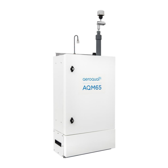
The Aeroqual AQM 65 is a compact air quality station designed for precise measurement of ambient pollution and environmental conditions. The AQM 65 platform is modular, each measurement parameter is selected by the user and added to the platform as an individual measurement module. An AQM 65 can be configured with 1- 6 gas modules as well as particulate and weather sensors. -
Page 8: Gas Modules
1.1 Gas Modules Several gas modules are available for integration in to the AQM 65. A full list of the gas modules which can be included is given in Table 1.1. The following section provides an overview of AQM 65 module design. A full specification of module performance is given in Table 1-1 1.1.1 Gas Module design... - Page 9 Each module contain two RJ-45 connections to allow the module to be connected to the RS-485 communications bus and each module contains a status LED. Figure 1-4 Gas sensor module with key components labelled MRK-D-0034 V2.0 Aeroqual AQM 65 User Guide Page | 8...
- Page 10 Direct none 140 - 160 reading or 10 ppm 0.6 % Table 1-1 Module specification table NOTE: Performance criteria are provided for factory test conditions and may change without notice MRK-D-0034 V2.0 Aeroqual AQM 65 User Guide Page | 9...
-
Page 11: Gas Flow Through Modules
The gas modules are connected in two rows inside the AQM 65 enclosure. There is one main gas inlet for sampling ambient air and one gas exhaust port both shown in Figure 1-6. Each gas module is connected to the pump via the Tygon exhaust manifold. - Page 12 This is discussed in more detail in Section 4.4.3.3. Figure 1-7 The vacuum side of the pump is connected to the exhaust manifold (blue rings). The AQM 65 inlet is connected to the inlet manifold (white rings). The pump has a by-pass valve to control flow rate.
-
Page 13: Particulate Matter (Tsp, Pm10, Pm2.5, Pm1.0) Modules
All of the modules used in the Particle Monitor system are held in the top row of the AQM 65. Figure 1-8 shows an AQM 65 with one Particle Monitor installed (three modules total) and Figure 1-9 shows an AQM 65 with two Particle Monitors installed (six modules total). - Page 14 AQM 65 shown in Figure 1-10. An AQM 65 that has a single Particle Monitor can be configured to measure either of these four size fractions simply by changing the inlet cyclone and making a small change in the software. This is described in Section 4.5 of the online training website.
-
Page 15: Particle Profiler Modules
There is no sharp cut cyclone used in the Particle Profiler; both the concentration and size are measured inside the optical particle counter. The three modules for the Particle Profiler are installed in the top right side of the AQM 65 enclosure. An AQM 65 will only ever have one Particle Profiler installed. -
Page 16: Optional External Sensors And Auxiliary Modules
Table 1-2 Summary of the difference between the Particle Monitor and the Particle Profiler. 1.3 Optional external sensors and auxiliary modules The AQM 65 can integrate a number of external sensors such as weather sensors, solar radiation and noise sensors. These sensors are mounted outside the AQM 65 enclosure. An auxiliary module (AUX) module is used to provide power to the external sensor and to process data from the sensor. -
Page 17: Temperature And Humidity Sensor
The compressor is located on the bottom of the AQM 65 behind a protective shield and can be removed if required. Temperature controlled air is passed into the compressor heat exchanger through vents in the bottom of the enclosure. - Page 18 Figure 1-14 Air conditioned air is constantly circulated in the AQM 65 enclosure. Air comes in to the enclosure at the top and exits through vents at the bottom The system manager module shown in Figure 1-15 is used to measure the internal temperature and control the compressor and heaters to maintain a constant internal temperature.
-
Page 19: Interfacing With The Aqm 65 Using Connect And Cloud
Aeroqual connect is the instrument’s operating system. The AQM 65 is controlled with an embedded PC, (ePC) which is running a webserver. The user connects to the AQM 65 using a web browser such as Firefox, Chrome or Safari. The connection can be over WIFI, Ethernet cable or cellular modem. -
Page 20: Aeroqual Cloud
1.5.2 Aeroqual Cloud Aeroqual Cloud gives you and other trusted users access to all of your instruments via secure third party servers. Use Cloud to: Communicate with your instrument from anywhere in the world at any time Use advanced charting features such as wind roses and pollution roses ... - Page 21 Aeroqual products. Engineers must also maintain regular service records in the Cloud Journal so that the Aeroqual team can evaluate the service and provide certification. See Section 4.7 for full details about the Advanced Engineer certification program.
-
Page 22: Quick Start Guide
With the fuse pulled out you will still hear the internal blower and will be to feel air flow coming from the top, See Figure 1-14. Figure 1-21 The fuse holder next to the 12 V rail can be pulled out to turn off the AQM 65 while mains power is attached. -
Page 23: Set-Up
Key points to consider for assembly and first power up: The AQM 65 runs on single phase mains AC power (90 – 305 VAC, 47 – 63 Hz). A detailed description of the DC power requirements (to assist with solar installations or UPS specifications) is given in the Appendix 3, ... -
Page 24: Unpacking
The AQM 65 is packaged in a rigid galvanised stainless steel shipping container which is lined with protective foam. The dimensions of the shipping container are 103 x 75 x 40 cm. The total weight of the AQM 65 in its shipping container is about 65 kg (150 lbs). -
Page 25: Wire Ac Mains Power And Initial Start-Up
Pull the 12 VDC fuse out from the fuse holder “off position” before testing the mains connection. Figure 2-3 The 12V DC fuse can be pulled out to turn off the AQM or pushed in to power the AQM 65 When you apply mains AC power (and with the 12 DC fuse in the “off”... -
Page 26: Attach Pm Inlet
Figure 2-5. NOTE: If your AQM 65 has two Particle Monitors as shown in Figure 1-9, the PM10.0 inlet is fitted on the right side and the PM2.5 is fitted on the left side. - Page 27 Figure 2-5 Remove the protective tape from the PM inlet Attach an O-ring to the aluminium retaining ring and apply a small amount of lubricant. Figure 2-6 Add the O-ring and a small amount of lubricant. MRK-D-0034 V2.0 Aeroqual AQM 65 User Guide Page | 26...
- Page 28 The inlet is wrapped in a thin film heater which has a white plug on the end. Carefully thread the white plug through the PM inlet port on the roof of the AQM 65. Figure 2-7 Gently feed in the power cable. The aluminium tube must push all the way in to the PM module.
-
Page 29: Attach Gas Inlet
When the AQM 65 is sampling ambient air in the field, a Kynar inlet fitting with mesh is attached to the Swagelok nut at the end of the sample cane. NOTE: Detailed instructions on gas flow measurement are given in Section 4.4.3.1 MRK-D-0034 V2.0... - Page 30 Figure 2-11 Connect inlet to AQM 65 and measure the flow rate to determine if connection is secure MRK-D-0034 V2.0 Aeroqual AQM 65 User Guide Page | 29...
-
Page 31: Wire External Third Party Sensors
If you are happy with the wiring then apply power, and log on to the Aeroqual Connect software. After some minutes you should see the parameters associated with the third party sensor being shown in the software. -
Page 32: Set Up Moxa G3111 Hspa Modem For Remote Communication
Figure 2-13 A SIM card must be inserted in to the modem and the Modem must be configured NOTE: It can take 12 to 24 hours for the AQM 65 to fully warm up and provide stable accurate readings. During this time the readings can be outside of what is expected MRK-D-0034 V2.0... -
Page 33: Re-Packing And Transport
Figure 2-14 The packing create uses retaining bolts which go through the AQM 65 mounting brackets. There is an additional supporting brace shown in the top right image which should be used. Figure 2-1 Shows the AQM 65 fully packed, the packing create has handles which makes carrying the AQM 65 easy. -
Page 34: Connect Software
Figure 3-1 The AQM 65 is controlled by an ePC. A modem can be included under the ePC. On the right is the Aeroqual Connect user interface, Aeroqual Connect is installed on the ePC. -
Page 35: Connecting To The Aqm 65 For The First Time
You must connect successfully to this WIFI network to achieve connection to the AQM 65. Figure 3-2 In WIFI access point mode the AQM 65 appears as a WIFI network in the lit of WIFI networks on your PC. -
Page 36: Options For Connecting To The Aqm 65
3.2 Options for connecting to the AQM 65 There are several options to establish a communication connection to the AQM 65. These require the communication settings to be changed in the Configure Instrument App shown in Figure 3-4. The communications settings are entered in to the third column. Details of each of these communication methods and how to set them up in the Configure App are given in the online training. -
Page 37: Direct Wifi
When this happens the AQM 65 will be automatically be assigned an IP address buy the router. You must find out what this IP address is so you can connect to the AQM 65. The WIFI or wired LAN IP address will likely be in the format: 192.168.XXX.XXX Figure 3-4 shows the Aeroqual Connect software with the assigned IP address in the address bar in the browser. -
Page 38: Connecting Using A Cellular Modem
Section 2.3 Figure 3-6 The MOXA modem uses a SIM card and it must be configured for use with the AQM 65 The Ethernet setting must be set to Auto DHCP client to use the MOXA modem, as shown in Figure 3-7c. - Page 39 AQM 65. The Ethernet mode is set to Direct (DHCP Server). In this configuration a laptop can be directly connected to the ePC using a Ethernet cable. Enter 10.10.0.1 to connect directly to the AQM 65. MRK-D-0034 V2.0...
-
Page 40: Resetting The Communication Settings Back To Factory Settings
WIFI network. The WIFI settings can be set back to Access Point mode and the AQM 65 will again appear as a WIFI network with the SSID name “Aeroqual AQM” and WIFI password “Aeroqual”. -
Page 41: Apps For Instrument Control And Calibration
Download data Connect User or higher Auto Export Connect + FTP Export Engineer or higher Manual sync Connect Engineer or higher Table 3-1 Software tools available to different user permissions MRK-D-0034 V2.0 Aeroqual AQM 65 User Guide Page | 40... -
Page 42: Charts
Figure 3-11 The table tool in the Manage Data app shows the data in a table with user configured date range and averaging MRK-D-0034 V2.0 Aeroqual AQM 65 User Guide Page | 41... -
Page 43: Download Data
(.csv). This file format can easily be opened in Microsoft Excel. Figure 3-12 The download data tool in the Manage Data app allows the data to be downloaded at user configured date range and averaging MRK-D-0034 V2.0 Aeroqual AQM 65 User Guide Page | 42... -
Page 44: Manual Sync
These files are then uploaded one by one using the manual sync upload tool in Cloud. Figure 3-13 The manual sync tool in the Manage Data app allow all data from the AQM 65 to be manually uploaded to the Cloud if a local data connection is not available MRK-D-0034 V2.0... -
Page 45: Service And Calibration App
When a service engineer visits the AQM 65 to perform routine service such as filer changes or flow checks, this can cause the data to read very high or very low. During service activities the AQM 65 can be put in to Service Mode by clicking the service mode button. This will tag the data as “service data”... -
Page 46: Diagnostics And Advanced
3.4.3 Diagnostics and Advanced The Diagnostic and Advanced App provides to instrument and individual module operating parameters and is used by Aeroqual technical support to troubleshoot and diagnose instrument condition. The Diagnostic and Advanced app provides real time information about the status of the modules and also allows operational settings of the modules to be viewed or edited. -
Page 47: Journal
NOTE: maintaining accurate and complete Journal entries is a pre-requisite of achieving Advanced Engineer status, a certification provided by Aeroqual to distributor engineers. Keeping service records is also a requirement under Aeroqual’s factory warranty Figure 3-16 The Journal automatically logs software changes, it also allows manual user entries MRK-D-0034 V2.0... -
Page 48: User Permission Types: Administrator, Engineer, User And Instrument Licences
3.5 User permission types: Administrator, Engineer, User and Instrument licences Each individual user of the AQM 65 may be given an individual username and password to access the AQM 65. There is no limit to the number of users which can be created. -
Page 49: Maintenance And Service
4 Maintenance and service Routine service and maintenance is required to ensure the AQM 65 performs optimally and to fulfil the requirements of the Aeroqual factory warranty. The frequency of some service activities such as filter changes will depend upon local environmental conditions. -
Page 50: Gas Flow Meters And Flow Measurement
Aeroqual measures standard flow; the Aeroqual standard conditions are 21.1 C and 101.3 kPa. Figure 4-1 A high quality flow meter is required for gas flow measurement of the AQM 65. Aeroqual recommends the Bios DryCal or the TSI 4140 (AQM R7) MRK-D-0034 V2.0... -
Page 51: Aqm 65 Service Mode And Using The Journal To Document Service
Figure 4-2 The AQM 65 can be put into Service Mode by clicking the button in the Calibration and Service app. This will label the data as "Service" in the inlet column so the data can be filtered. -
Page 52: List Of Maintenance Procedures
Journal using a manual user entry. See Section 4.3.2 4.4.1 Tools required for regular service and maintenance Service and maintenance of the AQM 65 requires basic tools such as Phillips head screw driver and adjustable spanner, and multimeter for checking electrical connections. -
Page 53: Replace Gas Sample Inlet Filter
Do not turn off the AQM 65; this procedure can be done with the AQM 65 turned on. NOTE: It is very important to check the AQM 65 inlet flow rate is correct after changing the filter to ensure there are no leaks. -
Page 54: Measure And Adjust Aqm 65 Inlet Flowrate And Module Flow Rates
NOTE: The AQM 65 inlet flow rate is equal to the sum of all of the individual flow rates. When the AQM 65 is new, the inlet flow rate is recorded in the instrument log book which is provided from the Aeroqual factory. This might change, especially if modules are added or removed. -
Page 55: Measure The Flow Rate Of The Individual Modules
Figure 4-5 To measure the flow rate, remove the inlet filter and attach the inlet flow adaptor. 4.4.3.2 Measure the flow rate of the individual modules The module flow rates are measured using a high quality flow meter such as the Aeroqual R7 or the Bios Dry Cal. See Section 4.2 ... -
Page 56: Adjust The Aqm 65 Inlet Flow Rate And Replacement Of The Gas Sample Pump
Adjust the AQM 65 inlet flow rate and replacement of the gas sample pump. If the AQM 65 inlet flow rate is found to be lower than expected, it could be because one of the modules has a leak or is blocked. -
Page 57: Replace Filter On Particle Monitor Or Particle Profiler
Recommended Monthly (depends on local conditions) service See Section 4.6 for further discussion on filter change frequencies. Online training.aeroqual.com: AQM 65 technical Training Section 4.3 reference Online video https://vimeo.com/120111907 The filters for the Particle Monitor are located inside the optical module. Use a large flat head screw driver to unscrew the filter housing on the front panel of the optical module. -
Page 58: Flow Check And Flow Adjustment Of The Particle Monitor And Particle Profiler
Frequency of Recommended Monthly. (See Section 4.6) service Online training.aeroqual.com: AQM 65 technical Training Section 4.3 reference Online video https://vimeo.com/75738199 The AQM R56 includes a flow adaptor which is fitted on the inlet, for the Particle Monitor it is fitted above the cyclone as shown in Figure 4-10. -
Page 59: Using The Buffer Chamber When Checking The Flow Of The Particle Profiler
Flow assembly. It is also part of the R20 Service kit. Figure 4-11 shows the buffer chamber installed between the flow meter and the profiler inlet. Figure 4-11 When measuring the flow on the Particle Profiler it is important to use the flow buffer chamber MRK-D-0034 V2.0 Aeroqual AQM 65 User Guide Page | 58... -
Page 60: Flow Adjustment Of Particle Monitor
The final adjustment can be a little tricky, turn the purge valve slowly. If it is not possible to reach 2.2 LPM at step 2 then there may be a leak or the pump might need to be replaced. MRK-D-0034 V2.0 Aeroqual AQM 65 User Guide Page | 59... -
Page 61: Flow Adjustment Of Particle Profiler
Figure 4-13 The flow rate of the Particle Profiler is set by adjusting the flow adjustment valve The flow rate of the Particle Profiler is adjusted to 1.0 LPM ± 0.05 LPM using the flow adjustment valve as shown in Figure 4-13. MRK-D-0034 V2.0 Aeroqual AQM 65 User Guide Page | 60... -
Page 62: Leak Check Particle Monitor And Particle Profiler
Parts required None Frequency of Recommended Every three months (See Section 4.6) service Online training.aeroqual.com: AQM 65 technical Training Section 4.6 reference Online video None 4.4.6.1 Leak check a Particle Monitor 1. Remove the TSP head and install the R23 vacuum gauge above the sharp cut cyclone 2. -
Page 63: Leak Check A Particle Profiler
Figure 4-15 Cap the purge and exhaust lines. Place the vacuum gauge on the inlet. Disconnect the power, observe the change in pressure. NOTE: The pressure change (leak rate) should be no more than 10 kPa in 10 seconds MRK-D-0034 V2.0 Aeroqual AQM 65 User Guide Page | 62... -
Page 64: Zero Calibration Check And Flow Check Of Particle Module
Parts required None Frequency of Recommended Every three months (See Section 4.6) service Online training.aeroqual.com: Dust Monitor technical training Section 4.4 reference Online video https://vimeo.com/ 78669407 checked 4.4.7.1 Check zero baseline of Particle Monitor The Particle Monitor has an automatic zero calibration function which runs every 12 hours. This procedure automatically changes the zero offset of the Particle Monitor. -
Page 65: Check The Auto Zero Calibration Flow Rate Of The Particle Monitor
Measure the positive flow coming out from the inlet and record this in the journal. The zero cycle takes approximately 6 minutes to complete. NOTE: Once the flow has been measured the TIMA parameter must be set back to 720 MRK-D-0034 V2.0 Aeroqual AQM 65 User Guide Page | 64... -
Page 66: Check The Zero Baseline Of The Particle Profiler
None Frequency of Recommended Every three months. (See Section 4.6) service Online training.aeroqual.com: AQM 65 technical Training Section 5.1 reference Online video https://vimeo.com/ 75738200 checked The TSP head, particle trap and cyclone disassemble easily for cleaning Figure 4-18 The TSP head and cyclone can be disassembled for cleaning MRK-D-0034 V2.0... -
Page 67: Replace Pumps In Pump Module
Typically the pumps last between 12 and 18 months. However the pumps should be replaced when the correct flow can no longer be maintained. Figure 4-19 The Particle Monitor contains two pumps; the Particle Profiler has one pump MRK-D-0034 V2.0 Aeroqual AQM 65 User Guide Page | 66... -
Page 68: Leak Check Gas Module
A gas module should be leak tight. Figure 4-20 A gas module can be checked for leaks by using a diaphragm pump and R7 flow meter If the module is found to have a leak, contact Aeroqual technical support technical@aeroqual.com for further support. -
Page 69: Add, Remove Or Replace A Gas Module
Changing the module configuration can be done easily on site at the monitoring location. Module replacement can be done with the AQM 65 power on. A change in the module configuration will result in a change of inlet flow rate. It is important to measure the inlet flow rate after the module change and document this in the instrument journal. -
Page 70: Removing A Module Without Replacing It
4.4.11.1 Removing a module without replacing it This can be done with the AQM 65 power left on. There is a software change required when removing or adding a module. Disconnect the vacuum and sample lines Remove one blue communications cable and one red and black power cable ... -
Page 71: Adding A New Module
4.4.11.3 Adding a new module This can be done with the AQM 65 power left on. There is a software change required when adding a module. You will need one blue communications cable and one black and red power cable. -
Page 72: Thermal Management System, Maintenance And Troubleshooting
The internal temperature set point is controlled by the ITemp H0 parameter in the module settings shown in Figure 4-24. The AQM 65 internal temperature is set to a default set point temperature of C is suitable for most environments. For AQM 65s installed in extreme cold or extreme heat, the set point can be changed to reduce the power demand placed upon the thermal management system. -
Page 73: Loss Of Thermal Control
AQM 65 Technical Training Section 3.3 reference If you observe a loss of thermal management as shown in Figure 4-24 contact Aeroqual technical support for advice technical@aeroqual.com. Figure 4-24 The internal temperature set point is set using the H0 parameter in the ITemp module settings. -
Page 74: Clean Tms Cassette And Condenser Fins
Do not brush against the fins as this can cause the fins to bend out of shape. Figure 4-26 Clean the condenser fins by brushing up and down parallel to the direction of the fins MRK-D-0034 V2.0 Aeroqual AQM 65 User Guide Page | 73... - Page 75 Figure 4-27 The cooling can be removed for cleaning. Make a note of the orientation of the fan and replace back the fan in the same position Carefully clean the blades of the fan with a damp cloth Replace the fan back in the same position. MRK-D-0034 V2.0 Aeroqual AQM 65 User Guide Page | 74...
-
Page 76: Check Tms Compressor Gas Pressure And Re-Fill
You will also need a valve to add to the can or cylinder of gas. Aeroqual can provide a charging hose (AQM R12) to connect the valve to the pressure gauge. Figure 4-29 Parts required for refilling the TMS compressor with coolant gas. The gas and valve must be... - Page 77 Make sure the AQM 65 has been running for at least 1 hour with the door closed before attempting to refill the compressor. Open the door to the AQM 65 and leave the door open during this process. Find the internal temperature sensor which is plugged into the side wall of the TMS module.
- Page 78 Attach one end of the hose to the pressure gauge and the other to the can or cylinder of R134a DO NOT open the valve on the cylinder yet. MRK-D-0034 V2.0 Aeroqual AQM 65 User Guide Page | 77...
- Page 79 The pressure variation is only a few PSI. It is important to try to achieve the target pressure point. The risk of UNDER pressurising is that the AQM 65 will not be able to control the internal temperature in hot outdoor conditions.
- Page 80 1. Use a pen or similar to press in the valve pin. Do this for a short time 2 seconds only. Watch the needle on the gauge. Wait (2 to 3 minutes) for the pressure to stabilise. 2. Repeat the process until the pressure reaches the target level. MRK-D-0034 V2.0 Aeroqual AQM 65 User Guide Page | 79...
- Page 81 Gently detach the valve connection. You will lose a very small amount of gas during this process. Remember to replace the protection cap after you remove the valve. Figure 4-37 Replace the protection cap once you have finished the process MRK-D-0034 V2.0 Aeroqual AQM 65 User Guide Page | 80...
-
Page 82: Factory Calibration Of Particle Monitor And Particle Profiler
It is recommended that the instrument engineer, over time, develops an appropriate servicing schedule for a particular site. Table 4.1 provides guidelines for service frequencies for the service activities documented in this user guide. MRK-D-0034 V2.0 Aeroqual AQM 65 User Guide Page | 81... - Page 83 Section 4.4.10 As required following module flow check Recharge compressor with gas Section 4.4.12.4 As required or when directed by Aeroqual technical support Add, remove, replace gas module Section 4.4.11 As required Table 4-1 Service frequency guidelines for various service activities MRK-D-0034 V2.0...
-
Page 84: Aeroqual Advanced Engineer Certification
How to achieve and maintain Aeroqual Advanced Engineer Certification 1. In-person training Aeroqual trainers regularly travel to train engineers at their office or laboratory. In-person training usually lasts between three to four days and may also include a field installation and/or commissioning. - Page 85 AQM 65 and Dust Monitor operation, maintenance and calibration. The training website contains detailed step by step procedures in video format for all common AQM 65 and Dust Monitor procedures. The training website is regularly updated with new material when the products and software are updated.
-
Page 86: Gas Module Calibration
The AQM 65 is calibrated using a two-point calibration procedure, first by delivering zero air to the AQM 65 inlet and adjusting the offset, and then delivering span gas to the AQM 65 inlet and adjusting the gain. Occasionally a multipoint calibration may be required. -
Page 87: Calibration Frequency
In the absence of a prescribed calibration schedule, which may be given if the AQM 65 is used under a compliance monitoring framework, the decision to calibrate should be made following a careful analysis of the data. -
Page 88: Guidelines For Purchasing Calibration Gas Cylinders And Gas Regulators
Aeroqual recommends is given in Table 5-1. The Calgaz cylinders have a C10 (5/8 – 18 UNF) thread (C10 fitting) which easily fits the Aeroqual two stage pressure gas regulator (Aeroqual part number AIC GASREG01), also shown in Figure 5-2 Note that two different cylinder types are specified;... -
Page 89: Cylinder Of Certified Zero Air And Certified Co2 For Co2 Calibration
5.2.3 Considerations for gas cylinder size Any gas cylinder size can be used with the Aeroqual AirCal systems, Figure 5-1 shows a range of cylinder sizes which can be used successfully with the AirCal 1000. Any of the cylinders in Figure 5-1... - Page 90 AirCal 1000 or AirCal 8000. On the right hand side are small size cylinders from Linde and Calgaz. These are more convenient and easy to transport. Figure 5-2 See the Aeroqual online training on connecting your gas regulator to your cylinder MRK-D-0034 V2.0...
-
Page 91: Calibration Safety
The AirCal 1000 is a stand-alone portable calibrator which is transported to the AQM 65 along with gas cylinders and set up on site and then removed from site following the calibration. The AQM O3CAL is a portable Ozone calibrator which can easily be carried to an AQM 65 for Ozone calibration. - Page 92 The outlet flow rate of the AirCal 1000 is fixed at approximately 2.5 LPM which means that it can be used to calibrate more than one AQM 65 simultaneously as shown in Figure 5-4. On the AirCal 1000 there are two gas inlet ports (1/8 Swagelok compression) and one gas outlet port (1/4 Swagelok compression).
-
Page 93: Aeroqual Integrated Calibration System Aircal 8000
The AirCal 8000 is an integrated calibration system whereby the gas cylinders and calibration system are installed inside the AQM 65 and permanently left in place. The AirCal 8000 can be scheduled to deliver calibration gas automatically or can be manually triggered remotely using Aeroqual Cloud without the need for a calibration engineer to visit the AQM 65. -
Page 94: Calibration Accessories: Tubing, Fittings, Gas Regulator
Aeroqual in meter quantities: part number CS TUBE27. These are shown in Figure 5-7. Figure 5-6 The AQM CALKIT connects the output of the AirCal 1000 to the input of the AQM 65 via a tee. MRK-D-0034 V2.0... - Page 95 Figure 5-7 The Aeroqual gas regulator is fitted with a 1/8 inch Swagelok compression fitting. Additional tubing for calibration can be purchased from Aeroqual: 1/8 OD tube Aeroqual part number CS Tube 27 and 1/4 OD Tube Aeroqual part number AS R66.
-
Page 96: Calibration Procedure
5.7.2 Using the AQM 65 Journal to log calibration details The AQM 65 journal will automatically record any changes to the offset or gain that is applied. You must log in the journal when you applied the zero air as this is not automatically recorded unless you are using the AirCal 8000. -
Page 97: Overall Calibration Workflow
4. Then performing a span calibration module by module. 5. Documenting all stages of the process in the instrument journal. 6. Final checks before leaving site and scheduling the next calibration. Figure 5-8 Flow schematic for calibration MRK-D-0034 V2.0 Aeroqual AQM 65 User Guide Page | 96... -
Page 98: Instrument Checks Before Starting Calibration
See Section 4.4.12 for a discussion on troubleshooting the thermal management system. Before you open the door, check the flow rate at the AQM 65 gas inlet and record the flow rate you measured in the journal. If the flow rate is outside of the expected range then you must find the cause. -
Page 99: Setting Up Calibration Equipment
Zero calibration using the AirCal 1000. Figure 5-9 Setup to perform zero calibration with AirCal 1000 The outlet of the AirCal 1000 is connected to the inlet of the AQM 65 using the tee fitting at the end of the AQM 65 CALKIT. ... -
Page 100: Span Calibration Using The Aircal 1000
Span calibration using the AirCal 1000. Figure 5-10 Setup to perform span calibration with AirCal 1000 The outlet of the AirCal 1000 is connected to the inlet of the AQM 65 using the tee fitting at the end of the AQM 65 CalKit. ... -
Page 101: Span Calibration Using The Aqm O3Cal Ozone Calibrator
Aeroqual with part number AQM O3CAL. Figure 5-11 Setup to perform span calibration with Ozone calibrator The outlet of the Ozone calibrator is connected to the inlet of the AQM 65 using the tee fitting at the end of the AQM 65 CALKITt ... -
Page 102: Zero And Span Calibration Using The Aircal 8000
When you are delivering zero or span gas you should measure excess flow out from the tee. The AirCal 8000 is controlled using the Connect/Cloud software. The AQM 65 calibration (Connect or Cloud) is used to change offset and gain. MRK-D-0034 V2.0 Aeroqual AQM 65 User Guide Page | 101... -
Page 103: Perform The Zero Calibration
NOx sensor module is stable. This module is ready to be assessed, for an offset adjustment. The SO2 value are neither drifting upward or downward but the values are noisy which has led to a high standard deviation, this module might be faulty. MRK-D-0034 V2.0 Aeroqual AQM 65 User Guide Page | 102... -
Page 104: Decide If A Zero Offset Adjustment Is Required
Make a note of this in the journal, and then carry on with the rest of the zero calibration and span calibration. This is because opening the door will cause instabilities in the internal temperature which will mean you’ll need to wait before continuing. MRK-D-0034 V2.0 Aeroqual AQM 65 User Guide Page | 103... -
Page 105: Perform The Span Calibration
20 and 40 minutes to calibrate. NOTE: The AQM 65 journal will automatically record any changes to the offset or gain that is applied. You must log in the journal when you applied the span gas as this is not automatically recorded 5.7.7.1... -
Page 106: Wait For The Module Response To Stabilise Towards The Span Gas
In the example given in Figure 5-15, the CO sensor module is being calibrated at a span point of 10.00 ppm CO. After 30 minutes the readings have stabilised at 9.017 ppm. Figure 5-16 Response of the O3 module towards 0.1 ppm Ozone MRK-D-0034 V2.0 Aeroqual AQM 65 User Guide Page | 105... -
Page 107: Decide If A Gain Adjustment Is Required
Current Gain Module reading and then use the equation to calculate the new gain. These values can all be found in the Calibration and Service Screen, shown in Figure 5-14 MRK-D-0034 V2.0 Aeroqual AQM 65 User Guide Page | 106... -
Page 108: Record Your Results In The Journal
Figure 5-17 is an example of a journal entry for an AQM 65 gas calibration. Figure 5-17 Use the journal to record details about the calibration that are not automatically captured by the instrument software 5.7.9 Pack up and final instrument checks, schedule the next calibration... -
Page 109: Particle Monitor Calibration
‘health’ of the internal components. 6.2 Field Calibration In order to perform a field calibration, your Aeroqual instrument must be located at the same site as a Reference PM instrument. This is called ‘Co-location’ and is widely performed in ambient air quality monitoring to assess the performance of a new instrument. -
Page 110: Steps To Perform A K Factor Correction
PM concentration. BAM and TEOM instruments run continuously and data is available at as low as 10 minute averages. This data can be noisy, so Aeroqual recommend that 1 hour or 24hr averages are used to minimise this noise. - Page 111 The goal is to create an excel spreadsheet, with 1 column of reference data, and 1 column of Aeroqual data, in the averaging period you have selected, for instance 1 hour or 24 hour or 24hr averages for the period of your co location.
-
Page 112: Appendices
Error conditions reported by Aeroqual Connect and Aeroqual Cloud software Connect and Cloud software will report two different types of error condition in the banner at the top of the page, these are ‘sensor offline” and “sensor failed” The error will also be listed in the AQM 65 journal. - Page 113 1. Failure to see the WIFI network broadcast by the AQM 65 If you cannot see the AQM 65 in your list of WIFI networks it is most likely because the WIFI setting is set to “Client Mode” and is not broadcasting. See Section 0.
- Page 114 Have optical module Section 4.5 serviced Failed laser Have optical module Section 4.5 serviced Dirty sample filters Change filter Section 4.4.4gentley Table 7-1 Common troubleshooting tasks and how to solve them MRK-D-0034 V2.0 Aeroqual AQM 65 User Guide Page | 113...
-
Page 115: Appendix 2 Aqm 65 Dimensions And Weight
Appendix 2 AQM 65 dimensions and weight The weight of the AQM 65 is approximately 40 kg (90 lbs). See Appendix 5 for mounting guidelines. MRK-D-0034 V2.0 Aeroqual AQM 65 User Guide Page | 114... -
Page 116: Appendix 3 Dc Power Consumption Of The Aqm 65
Appendix 3 DC Power consumption of the AQM 65 Occasionally mains AC power is not available at the site where the AQM 65 is installed and an alternative power solution is required. There are two variables which determine the power requirements in Watts (W) for an AQM 65. - Page 117 48.9 70.6 To use the calculator type “YES” in the cell next to the module installed in your AQM 65. All AQM 65s will have the Embedded PC, Sample Pump, and System manager. We recommend to include the Moxa modem, the other modules are optional and will be unique to your AQM 65.
-
Page 118: Appendix 4 Co2 Module Calibration
Demand flow regulator for CO2 zero and span calibration A demand flow regulator will allow the AQM 65 to control the flow rate. Eg if the AQM inlet flow rate is 0.45 LPM then the demand flow regulator will deliver exactly 0.45 LPM. The calgaz.com demand flow regulator part number (DFR) 2001 is suitable for use with the zero grade air and CO2 calibration gas. - Page 119 Figure 7-1 Calibration setup for calibrating CO2 Figure 7-2 Left: Closed tee used with demand flow regulator. Right: Open tee used with fixed flow regulator. MRK-D-0034 V2.0 Aeroqual AQM 65 User Guide Page | 118...
-
Page 120: Appendix 5 Aqm 65 Site Installation And Commissioning With Mounting Examples
See Appendix 2 for AQM 65 dimensions and weight. Most sites will require a way of securely mounting the AQM 65. Pole Brackets (89 mm / 3 ½ “304 Stainless U-Bolt) are included to mount the instrument on a pole, anchored to the ground. (Figure 3) Small platforms have also been used successfully too (Figure 1). - Page 121 Figure 1: The AQM 65 is mounted on a stand and is secured to a pole. A wind sensor (Gill) is mounted to the top of the pole. Figure 2: It is very important to maintain good air flow underneath the AQM 65. The...
- Page 122 Figure 3 The AQM 65 is mounted to a pole, an additional power point is added to allow a laptop or Aircal 1000 calibrator to be plugged in. The two images below illustrate some potential installation problems which will cause problems.
- Page 123 Design concept for AQM 65 stand with extended pole for mounting metrology sensor Figure 5 A stand with an open base allows air flow around the Temp/RH sensor. The stand is held on a concrete base. MRK-D-0034 V2.0 Aeroqual AQM 65 User Guide...
- Page 124 Write a comment in the Journal that commissioning is complete. Exit Service mode. NOTE: It can take many hours (up to one day) for the AQM 65 to fully warm up and provide stable readings. During this time the readings can be negative or outside of what is expected Complete the Commissioning report and provide to customer This report details the settings of the instrument at the time of commissioning.
-
Page 125: Appendix 6 Gas Calibration Systems From Other Suppliers
Teledyne, Thermo Fisher or Ecotech. An example of a Teledyne gas dilution calibration system is shown in Figure 7-3. A disadvantage of these systems is they are not as portable as the Aeroqual AirCal 1000, however some gas dilution calibration do include an Ozone generator and have the ability to perform gas phase titrations (GTP). - Page 126 Figure 7-3 Left: Ecotech and Teledyne calibration system. Top Right: Drying agent molecular Sieves. Bottom right: Aeroqual R41 humidifier. Figure 7-4 The Aeroqual R41 humidifier is placed between the outlet of the calibrator and the inlet of the AQM 65 MRK-D-0034 V2.0...
-
Page 127: Copyright
2. The Aeroqual AQM 65 Monitor complies with EN 61000-6-3:2001 3. The Aeroqual AQM 65 Monitor complies with Part 15 of the FCC Rules. Operation is subject to the following two conditions: (1) these devices may not cause harmful interference, and (2) these devices must accept any interference received, including interference that may cause undesired operation.
Need help?
Do you have a question about the AQM 65 and is the answer not in the manual?
Questions and answers