
Related Manuals for FARMSCAN Jackal


Summary of Contents for FARMSCAN Jackal
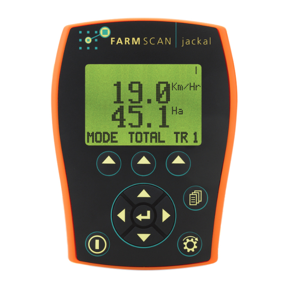
- Page 1 FA R M S C A N one monitor, many possibilities area meter batch meter tacho meter rate monitor spray monitor pressure monitor surveillance monitor...
- Page 3 DISCLAIMER The warranty offered on Farmscan product is limited to the re- pair or replacement of the faulty goods. No liability will be ac- WARRANTY IS VOID cepted for loss of profit or productivity. power is not connected as described in section 2.4.
-
Page 4: Table Of Contents
Depth ..........17 Part Number: AM-Jackal Version 1.0... - Page 5 Remote Run/Hold Kit ........30 Part Number: AM-Jackal Version 1.0...
-
Page 6: General Description
There are 10 trip counters as well as an overall total allowing the operator to track numerous jobs in a period of work. The Jackal can be put ‘on hold’ by the operator or by a suitable signal from the machinery, so that periods of machine operation that should not accumulate as a work total can be excluded from trip totals. -
Page 7: Installation
Parts pictorial with parts numbered as per Section 2.1. 2.3. MOuNTING AND INSTALLATION The Jackal is provided with a suction window mount. (Figure 1) Slide mount onto unit and push sideways to lock into place. Make sure you hear a click of the mount locking into place. -
Page 8: Connections
J a c k a l 2.4. CONNECTIONS The connector on the rear of the Jackal has the following function: GND (Ground/Earth/0V) IN1 (Coil/Prox/Reed sensor) IN13 (Run hold) IN2 (Prox/Reed sensor) IN12 (Alarm/Switching sensor) IN3 (Prox/Reed sensor) IN11 (Alarm/Switching sensor) -
Page 9: Sensor Compatibility
BATT GND BATTERIES (BLACK) Figure 3: Correct battery connection for possible battery configurations 2.4.2. SENSOR COMPATIbILITY The Farmscan sensors that are compatible with these inputs are shown in the table below. For Sensor Options Name Terminal Inputs • • •... -
Page 10: Operation
RuN mode, a little bar rotates in the top right corner to signify that the monitor is active. When the monitor is in hOLD mode this bar is not visible and “ON HOLD” is displayed at the top of the screen. Part Number: AM-Jackal Version 1.0 Published: June 1, 2009... -
Page 11: Soft Keys
3.1.4. SOFT kEYS The Jackal has 3 soft keys placed directly under the LCD. These keys will change function in different menus. The current function of the soft key is indicated at the bottom of the screen directly above the button. In the main menu the soft keys provide access to information display MoDE, ToTAL and TRIP memories as described in subsequent sections. -
Page 12: Trip
3.2.2. TRIP The Jackal features 10 trip counters as well as totals counters. The counters accumulate whenever the monitor is off hold. The TRIP menu is entered into from the main screen using the soft- key under the TRIP legend. -
Page 13: System Menu
To enter the system menu: Ensure the Jackal is turned off Turn On device When the Jackal ‘Splash Screen’ is displayed, press and release the MEnU button. System Menu Should Appear, as shown in Figure 6. nAV keys to change the user selectable options. -
Page 14: Input Setup
Only INPuT 1 can accept coil sensor inputs. If the desired setup uses a coil sensor do not use INPuT 1 for any other sensors. 4.1.1. SPEED The Jackal can use and display speed information, as shown in Figure 12, from: a wheel sensor; GPS input; or Radar Speed input. 4.1.1.1. WhEEL AND RADAR SPEED 4.1.1.1.1. - Page 15 WILL RESuLT IN INCORRECT INFORMATION. 4.1.1.2. GPS SPEED The Jackal is capable of using any GPS that produces NEMA GPS strings containing VTG in- formation, communicated using the RS-232 Port. GPS SPEED is enabled through the System Menu. Setting Up GPS SPEED : Enter the System Menu as described in section 3.2.4.
-
Page 16: Rpm (Shaft Speed)
RPM option. nAV keys to set DIVIDE value ( DIVIDE value is the number of magnets or teeth on the shaft, and therefore the number of pulses received by the Jackal per shaft rotation). NAV keys to set alarm points. - Page 17 Any excess to the batch AMOuNT is recorded in LTS OVER ( GAL OVER ) as shown in Figure 19. Press and hold oVER until the Jackal beeps to update the compensation for valve turn off time.
-
Page 18: Rate
Jackal counts the pulses Enter the known amount of product run through the flow sensor in liters and press EnTER. Hold SET for approximately 1 second and the Jackal will calculate the calibration FACTOR . FACTOR is known, enter this FACTOR •... -
Page 19: Analogue Inputs
Calibration requires two values. The low value sets the zero point. If the sensor ever produces a lower output that the low point used for calibration the Jackal will display zero not a negative number. Therefore the Jackal must be calibrated using the lowest value expected in operation. -
Page 20: Pressure
= P2 – P1 = 250 – 0 = 250 P2 – P1 ) The Jackal will calculate A/D counts per unit of pressure. ALM LO and ALM hI alarm values in the indicated units using the nAV Enter the keys. - Page 21 Maximum values are determined by which ever is lowest of either the voltage input limit (5V), or the sensor output limit. The Jackal does not calculate an offset for the sensor. Therefore if the lowest pressure measured by the sensor is 1 Atmosphere (14.7 PSI, 101 kPa) the absolute pressure measurement will be e.g.
-
Page 22: Depth
P1 and P2 will provide a more accurate calibration. The Jackal assumes that the Pressure Sensor output changes linearly with a change in pressure, as shown in Figure 21. In practice sensors may not be perfectly linear. It is recommended that pressure sensors used are operated in the linear region of sensor output. - Page 23 High and Low depths used should be representative of highest and lowest depths expected during operation. A/D LO value used for calibration defines what the Jackal considers 0. Therefore all have a higher A/D value than the A/D LO value used in calibration.
-
Page 24: Tank / Bin Level Alarm Inputs
12 volt is applied to input. NOTES: There is an internal pull up resistor so a floating or 12 volt input is not differentiated. Therefore, if the alarm Polarity is set LOW and the sensor is disconnected from the Jackal ALARM WILL NOT TRIGGER. -
Page 25: Run Hold Input
IS NOT LOW and the sensor or external switch is disconnected from the Jackal (either by the user or via connector or cable failure) the jackal will remain in RUN mode irrespective of a change in machinery or switch state. -
Page 26: Example Configurations
The main screen should display as shown in Figure 31 and each input will display ‘NOT USED’ when cycled through using the MEnU key. If the Jackal does not display as shown in Figure 31, use the MEnU and nAV keys to inactivate inputs. -
Page 27: Tacho Meter
C O N f I G u R A T I O N S 5.2. TAChO METER The Jackal can monitor up to 6 shafts, displayed as shown in Figure 29. Shaft RPM is displayed in order of input number. RPM monitoring can be used in conjunction with SPEED monitor- ing, RATE information, bin / tank level ALARMS and PRESSuRE or DEPTh monitoring. -
Page 28: Flow Meter
5.4. BATCh METER When configured as a Batch Meter, as shown in Figure 37, the Jackal uses a flow sensor and solenoid valve to accurately meter liquid vol- umes. The output of the Jackal (Terminal B8 and B9) is suitable for direct connection to a 12 volt solenoid valve. -
Page 29: Airseeder Surveillance Monitor
Any excess to the batch AMOuNT is recorded in LTS OVER ( GAL OVER ) as shown in figure 38. Press and hold oVER until the Jackal beeps to update the compensation for valve turn off time. - Page 30 Airseeder monitor as described in this section ToTAL (A), TRIP 1 (B) and TRIP 2 (C) (currently active trip, indicated by the X) screens for the Figure 42: Example of the Example Airseeder configuration Part Number: AM-Jackal Version 1.0 Published: June 1, 2009...
-
Page 31: Sensor Installation
Other sensors that require +12 volts as well as signal and ground/earth will have 3 wires, such as flow sensors, bin level sensors and pressure sensors. All connections to the Jackal are provided via two 11 way terminals. The terminals are described in section 2.4. -
Page 32: Compatible Sensor Kits
I N S T A L L A T I O N 6.2. COMPATIBLE SENSOR kITS There are a range of separate sensor kits available for the Jackal. Below is a list and brief descrip- tion of these kits. Possible... -
Page 33: Installing Sensor Kits
If you are intending to use a ‘Coil’ sensor do not use port B1 DO NOT PIGGY bACk WhITE SIGNAL WIRES INTO SAME PORT It is highly recommended that the ferrules, supplied with the Jackal kit, should be crimped to bare wire ends. This minimises chance of any stray wires bridging. -
Page 34: Two Wire 'Coil' Sensor Kits
1 coil port. sensor inputs. Black is GROuND and white is SIGNAL . NOTE: do not use any other Ground on the Jackal or ve- See Section 4 for how to setup an input and hicle for sensors calibrate a sensor once installed. -
Page 35: Bin / Tank Level Sensor Kits
Figure 47: Jackal ports capable of accepting Bin / Tank Lev- move to one of the ports shown that is free. el sensor inputs. Black is GROuND , Red is POWER and white is SIGNAL . - Page 36 S C A N one monitor, many possibilities B1 / 6 Tarlton Crescent | Perth Airport Western Australia 6105 E: service@farmscan.net W: www.farmscan.net.au FARMSCAN is a registred Trademark of Computronics Corporation Ltd | ABN 58 009 089 025 | ASX : CPS...
Need help?
Do you have a question about the Jackal and is the answer not in the manual?
Questions and answers