Table of Contents
Advertisement
Quick Links
Advertisement
Table of Contents

Related Manuals for FARMSCAN 74V1


Summary of Contents for FARMSCAN 74V1
-
Page 2: Table Of Contents
Screen & Layout Setup ............................85 Display ..................................90 Front Screen Control ............................. 93 Spray Section Control Operation .......................... 94 74V1 Menu Layout (Tank) ............................. 97 74V1 Menu Layout (Machine) ..........................98 74V1 Menu Layout (Display) ..........................99 UniPOD Pinout ..............................100... -
Page 3: Introduction
The 7000 terminal can be used in many agricultural applications including but not limited to: Spray Controller Model 74V1 Variable Rate Controller Model 7500 Spreader Rate Controller Model 7300 ... -
Page 4: Technical Specifications
All details are without guarantee. Errors and omissions excepted. CANopen® is a registered community trade mark of CAN in Automation e.V. Linux® is a registered trademark of Linus Torvalds in the United States and other countries. February 2017 www.farmscanag.com AM-74V1-4... -
Page 5: 74V1 Spray Controller
The 74V1 cab module is connected via CANbus to the flow sensor/ flow control valve and section valves on the sprayer by our UniPOD to provide section controls, a second spray line or dump valve control. -
Page 6: Parts List
** Item D (CANbus Terminator) – Normally this will have an extension cable connected to this port that runs down to the UniPOD or a “Y” style cable for the Smart switch. The CANbus terminator will then plug into the harness at the UniPOD end. – CANbus OUT February 2017 www.farmscanag.com AM-74V1-4... - Page 7 (2 Pin Deutsch Style) CANbus extension cables (optional): Part Number Description AC-2012 2m CANbus extension Cable AC-2012-5 5m CANbus extension Cable AC-2012-10 10m CANbus extension Cable Smart Switch (optional): Part Number Description 7000SS-SPR Smart Switch with Splitter cable February 2017 www.farmscanag.com AM-74V1-4...
- Page 8 The mounting position should not subject the 7000 terminal to high levels of vibration. MOUNTING HARDWARE Assemble the backing plate to the rear of the 74V1 terminal as described below: NOTE: A size 4 Allen key is required to attach the mounting plate & RAM mount.
- Page 9 Use cable ties to secure the power cable safely away from hot or moving parts. Connection to battery terminal bolts must be kept clean and tight. See the diagram below for typical battery connection schemes. February 2017 www.farmscanag.com AM-74V1-4...
- Page 10 NOTE: As a precaution, avoid running the controller harness alongside other electrical cables in the cab. Use cable ties to secure cable away from risk of damage. 74V1 Monitor UniPOD to control bank Run CANbus cable from Monitor to UniPOD.
- Page 11 The UniPOD has two (2) status indicator lights located at the top right hand side of the UniPOD mainboard (inside the enclosure). This should be left visible at all times for troubleshooting. (SOLID): 12v Power is connected to the UniPOD GREEN (SOLID): Fixed CANbus communications to 7000 RED/GREEN (FLASHING): Run Mode February 2017 www.farmscanag.com AM-74V1-4...
-
Page 12: Installation Of Terminal - Smart Switch - Unipod
AC-7722 : Flow Control Adapter Plug ONLY 3 WIRE SECTION VALVES CAN BE USED Connect sections as per labels WITH THE 74V1. 3 TO 2 WIRE VALVE ADAPTERS AC-7721 : Section ARE AVAILABE FOR PURCHASE Valve Adapter Plugs... -
Page 13: Installation (Sensors)
5. A 5m-extension cable can be purchased to connect the sensor to the sprayer loom connector marked ‘wheel’. (Farmscan Ag Part # AC-205/5m or AC-210/10m) 6. Use cable ties to secure sensor cable away from risk of damage or chaffing. - Page 14 Installation (Sensors) GPS SPEED INSTALLATION (Farmscan Ag Part # T-185) In applications where a non-driven ground wheel is not available, a GPS antenna may be used. An optional GPS Sensor kit is available or if you have existing GPS system that can output NMEA strings this can be used also.
- Page 15 AH-630 1” Hose tail The 74V1 is designed to work with almost any spray valve on the market today. If you do not wish to use our preferred option please contact us for compatibility. Valve adapters maybe required. February 2017 www.farmscanag.com...
-
Page 16: Control Bank Installation
Suitable for broad acre boom sprays and high volume air blast sprayers. DIRECT CONTROL Used to throttle (restrict) the main delivery line thereby regulating the volume of material delivered to the section controls. NOTE: Suitable for ultra-low volume applications from 1 L/min – 80L/min. February 2017 www.farmscanag.com AM-74V1-4... -
Page 17: Explanation Of Components
FLOW SENSOR (Farmscan Ag Part # AA-230/A | 10-100L/min) The flow sensor provides continuous feedback to the spray controller, which regulates the flow control valve to maintain the required volume of liquid delivered to the section valves. - Page 18 NOTE: When choosing to use 2 Line control you must purchase the AC-7410 (10 section harness) to ensure enough outputs are available. Please contact Farmscan Ag Support to discuss your options. February 2017 www.farmscanag.com AM-74V1-4...
- Page 19 The second spray line section valve must tee off the main delivery line after the flow sensor and flow control valve. 3 wire motorised valves: Red = +12V Black = Negative Colour = Trigger February 2017 www.farmscanag.com AM-74V1-4...
- Page 20 The first and second spray line section valves should be plumbed onto a common manifold and must tee off the main delivery line after the flow sensor and flow control valve. 3 wire motorised valves: Red = +12V Black = Negative Colour = Trigger February 2017 www.farmscanag.com AM-74V1-4...
- Page 21 CONNECTIONS (Farmscan Ag Part # AC-7405 “5 Section” or AC-7410 “10 Section”) A CANbus loom connects the 74V1 to the UniPOD. The UniPOD connects to the controlled elements (flow control valve, section valves, dump valve etc.) Connect the labelled connectors on the loom to their respective sensors (flow, wheel and pressure) or equipment (section valves and control valve).
-
Page 22: Start Guide
The 74V1 will be set up with basic screens and layouts provided by factory defaults. Factory defaults may differ if the 74V1 is setup OEM specific. For optimal setup of the 74V1, the steps below should be performed in the following order: Set up CANbus/UniPOD... -
Page 23: 74V1 General Overview
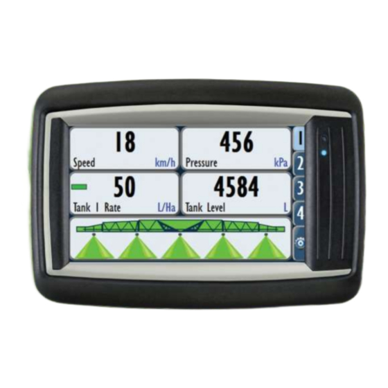
74V1 General Overview 74V1 GENERAL OVERVIEW The following pages are intended to provide a brief overview only. Setup instructions can be found by following the page numbers as described on the previous page. LED STATUS LIGHTS - OVERVIEW The 7000 has two (2) status indicators on the right hand side of the screen. - Page 24 74V1 General Overview FRONT SCREEN - OVERVIEW 1. Settings Menu a. Select the Settings tab (represented by the Settings icon which looks like a gearwheel) once to display the Settings menu. b. Select an option by pressing one of the icons in the Settings menu.
- Page 25 74V1 General Overview SETTINGS MENU - OVERVIEW The Settings menu allows for the setup of the 74V1. Select the Settings tab (5 tab) from the Front Screen (it looks like a cog). 1. Setup Menu Select the Setup Menu icon to open the Setup & Settings menu.
-
Page 26: Device Menu Overview
Select the Tank tab to display it. b. This tab contains settings for the tank, any products associated with the tank and enables product calibration. This also defines the number of tanks the 74V1 is controlling. 2. Machine Tab a. - Page 27 7000 terminal. A widget can be setup on Tab or Tile. By default the 74V1 will display the MAP widget on TAB 3. Only one active job & coverage can be displayed at any time.
- Page 28 Select this button to open a menu allowing the user to change in which units Job details are displayed. 10. Export to CSV a. Allows the operator to export the selected Jobs via CSV (text) onto a USB memory stick. February 2017 www.farmscanag.com AM-74V1-4...
- Page 29 These buttons will be visible if multiple Alarms exist and cannot be displayed on one screen. a. If more than 5 Alarms are listed in the table then the Up/ Down buttons will allow the user to scroll through the table to display all Alarms. February 2017 www.farmscanag.com AM-74V1-4...
- Page 30 If an Alarm is tripped and the state is in Alarm then the reset button will NOT reset the Alarm. NOTE: Making the Alarm inactive will turn off Alarm indicators, the Alarm will no longer be monitored when Inactive though. February 2017 www.farmscanag.com AM-74V1-4...
- Page 31 Allows for lockout facility if the multiple users option is activated. 3. About Lists the details of the current 7000 series device including version numbers & unlock codes 4. Test Used for diagnostic purposes only. THIS COMPLETES THE DEVICE OVERVIEW February 2017 www.farmscanag.com AM-74V1-4...
- Page 32 Machine Setup MACHINE SETUP The Machine tab allows setup of the master control features on the 74V1 used for boom spray operation. Control (1) A. Control Speeds (Minimum, Slow Hold, Prime) B. Auxiliary Setup (Dump, Output) NOTE: Will only display when UniPOD is attached.
- Page 33 If the implement drops below this speed then the spray valves will shut off; if a dump valve is fitted to the system it will open. NOTE: Dump valve must be set up in Auxiliary Setup. February 2017 www.farmscanag.com AM-74V1-4...
-
Page 34: Machine Setup
3. Navigate back to this menu and highlight Slow Hold Speed. 4. Adjust to set the desired hold speed (km/h). Operating with Slow Hold active will mean the product is being over applied and may cause damage to crop! February 2017 www.farmscanag.com AM-74V1-4... - Page 35 When in Prime Mode, the flow control is regulated as if the implement was travelling at the Prime Speed. b. If the implement exceeds the Prime Speed, Spray Section Control will revert to Run Mode. Control Rate Revert Rate @ to Run Prime Mode Speed Speed Prime Speed February 2017 www.farmscanag.com AM-74V1-4...
- Page 36 Machine Setup AUXILIARY SETUP / DUMP VALVE (1B) By default, the 74V1 will select the output/ valve configuration depending on what number of sections (available outputs) the UniPOD was purchased with. However, Auxiliary Setup allows the user to customise which output control goes to which valve or sensor. This is required to be setup when using a DUMP Valve.
- Page 37 The pressure sensor measures spray line pressure at the section manifold to provide a pressure readout and to control the slow hold and second spray line functions (if used). The 74V1 has the ability to monitor 2 pressure sensors when 2 tanks & 2 UniPOD’s are connected.
- Page 38 1. Manually add the Voltage High (as per manufacture specifications), or 2. Adjust your pressure manually to the High point and select SET VOLT. This will take the value from the input voltage and automatically insert. (Refer to manual pressure gauge if fitted.) February 2017 www.farmscanag.com AM-74V1-4...
- Page 39 Normally that would be ON = 300-350kpa (44-51 psi), OFF = 100-150kPa (15-22 psi) for any size nozzle. Spray line is only compatible when purchased with the AC-7410 (10 Section Harness) Please refer to the Auxiliary Setup on PAGE 35 to specify your second line valve. February 2017 www.farmscanag.com AM-74V1-4...
- Page 40 Machine Setup MEASUREMENTS (2) For the 74V1 to correctly display and control the desired application rate, an implement width needs to be entered. SECTION WIDTH – SINGLE (2A) 1. Deselect (untick) the Use Section Control checkbox. 2. Select the Width button.
- Page 41 5. Select the + button to add sections with a width entered in the previous step. 6. Select the – button to remove sections. 7. Select individual sections to modify individual section widths. 8. Select the green Tick button. 3 / 4 THIS COMPLETES THE MACHINE MEASUREMENTS SETUP February 2017 www.farmscanag.com AM-74V1-4...
- Page 42 Machine Setup SPEED-GPS (3) The 74V1 has the ability to use a GPS as Speed input or a standard magnet/ sensor input for ground speed. Setup options are described below: WHEEL SENSOR (3A) 1. Navigate to Wheel. 2. Select the Use Wheel Sensor checkbox 3.
- Page 43 2. Mark a point at the bottom of the tyre and on the ground (normally bottom centre). 3. Drive one full rotation of the wheel and stop when marked point on tyre is centre bottom. 4. Measure between the two points. 5. Insert the measurement on the m/Pulse button. February 2017 www.farmscanag.com AM-74V1-4...
- Page 44 Baud rate is selected. If no data is being received, refer to SERIAL INPUT at the bottom of the page to ensure data is being received and the correct BAUD rate is selected. February 2017 www.farmscanag.com AM-74V1-4...
- Page 45 Tracmap NZ for spreaders & sprayers or the Trimble Universal Variable Rate Protocol (TUVR). The TUVR protocol can communicate both the automatic rate and section control to our 74V1. Please note that the TUVR protocol must be unlocked on your Trimble display. Contact your local Trimble dealer for further information.
- Page 46 5. Select the UniPOD ID of the UniPOD connected first on the physical wiring harness 6. Select the green Tick button to save changes. If more than one UniPOD is installed then repeat this procedure for each extra UniPOD. February 2017 www.farmscanag.com AM-74V1-4...
- Page 47 If more than one UniPOD is installed then repeat this procedure for each extra UniPOD. NOTE: A minimum voltage of 12.1v is required for the UniPOD to operate correctly. Before calling the Farmscan Ag Service department please ensure the minimum voltage requirements are met. February 2017 www.farmscanag.com...
- Page 48 If an external switch box is or is not connected on the CANbus this will be indicated as OK or None. RUN/HOLD SWITCH (4D) If an external Run/Hold is or is not connected on the CANbus this will be indicated as OK or None. When connected, the current state of the switch will also be displayed. February 2017 www.farmscanag.com AM-74V1-4...
- Page 49 MAPPING – VRC PRESCRIPTION FILE (6) The 74V1, when connected to a GPS has the ability to control to a prescription file. 74V1 Prescription files are a standard SHAPE file format and loaded via a USB drive. Talk to your agronomist or GIS expert to create your files.
- Page 50 The main working screen that displays the application rate tile will now be displayed with a GREEN DOT indicating the 74V1 is controlling to the VRA file. As you drive over the field. Pressing on the APP RATE Tile will reveal the LIVE Rate.
- Page 51 Select to change flow meter calibrations for a different product.. 7. Add/Remove Tank a. Use this to add a second tank to your setup. NOTE: Please note that your UNIPOD must be programmed & setup for this type of dual rate application. February 2017 www.farmscanag.com AM-74V1-4...
-
Page 52: Tank Setup
Select the Level Alarm button to input the tank level as either an estimated (computed) or external (tank level sensor) value. If unsure, leave option as ESTIMATED 5. Select the green Tick button to save your changes. February 2017 www.farmscanag.com AM-74V1-4... - Page 53 Enter your desired application rate step for the tank. NOTE: The step size that the application rate will change by when being adjusted from the Front Screen rate tile. 4. Select the green Tick button. February 2017 www.farmscanag.com AM-74V1-4...
- Page 54 SETUP (CONTROL VALVE / PROPORTIONAL VALVE) (4) It’s important to set up your flow control/ proportional valve correctly to maintain regulated flow while changing speeds. Under Control Valve we have some pre-defined valves common to standard Farmscan Ag setups. Custom (define your own settings) ...
- Page 55 Warning: Changing these values can be detrimental to your valve if not done correctly. Proceed with caution! Type: The operational type of the valve, in a 74v1 this will always be a Motor +/– Valve. Maximum: The maximum voltage to apply to the valve. 12v is the maximum and default value Minimum: The minimum voltage to apply to the valve.
- Page 56 (i.e. when changing rates).The lower the time, the quicker the rate will change. The higher the value, the longer the rate will take to change to the new desired application rate. Suggest 0.5 as a good starting point. February 2017 www.farmscanag.com AM-74V1-4...
- Page 57 3. Ensure that the Sensor reading is display a value in L/s or RPM – This ensures you are getting a reading from your flow meter. 4. Select the red Tank 1 button to disable it. 5. Select the red CROSS button to exit the test screen. February 2017 www.farmscanag.com AM-74V1-4...
- Page 58 FLOW CALIBRATION (FLOW METER) (6) Each tank must be calibrated to a flow meter to allow the 74V1 to achieve the correct applied rate. The 74V1 has the ability to recall multiple pulse per litre (PPL) calibration factors for multiple machine & flow meter setups.
- Page 59 Enter a name for the calibration. Polmac is used in the example above b. Select the green Tick button. 2. To remove a flow meter calibration: a. Select the desired line. b. Select the – button. 3. Select the green Tick button. February 2017 www.farmscanag.com AM-74V1-4...
- Page 60 2. Cal Unit will be default to L. There is no need to adjust this. 3. Select the Calibrate button (refer to the next page). You will need to choose your calibration method from the next 2 sections. February 2017 www.farmscanag.com AM-74V1-4...
- Page 61 If the value is known, insert the value in the Pulse/L window as shown below. Even though on the tag attached to the flow sensor included in the kit there is a base calibration factor, this factor should be checked. Refer to Method 2 (in the next section). February 2017 www.farmscanag.com AM-74V1-4...
- Page 62 3. Enter the Calibration Rate in Percentage at 50%. (This will open the control valve to half rate as not to cause any damage to your pump) 4. Select the green Tick button to return to the previous screen. February 2017 www.farmscanag.com AM-74V1-4...
- Page 63 PPL Method. If the calculated FLOW CAL (Pulses/L) differs greatly from the sensor calibration tag attached to the flow meter, repeat the test. Sometimes it’s best to do this 3 times to obtain a better average. February 2017 www.farmscanag.com AM-74V1-4...
-
Page 64: Jobs (2)
Replace the front screen data related to this job (As below) Simply select the new Job that you wish to display on the Front Screen Tile to record the new job details. February 2017 www.farmscanag.com AM-74V1-4... - Page 65 AC-7000 harness. It is recommended that only one job is active and coverage is recorded at one time. Farmscan Ag recommends placing the live coverage map on Tab 4 as it displays in a whole screen format. Refer to PAGE 91 for example view.
- Page 66 2. Select the Job you want to view the details of (the Job will be highlighted blue). 3. Select the Job details button. RESETTING JOB DETAILS You can reset the job details by selecting the RESET icon (see below). This will reset all totals. February 2017 www.farmscanag.com AM-74V1-4...
- Page 67 1. Navigate to the Job page. 2. Select the Edit Job Units button. 3. Select the <- and -> buttons to change the units used for duration, distance and area. 4. Select the green Tick button to accept these changes. February 2017 www.farmscanag.com AM-74V1-4...
- Page 68 2. Select the Job you want to delete (it will be highlighted blue). 3. Select the – button WARNING: You will lose all of the information stored in this Job if you delete it. 4. Select Remove in the Warning screen. February 2017 www.farmscanag.com AM-74V1-4...
- Page 69 If successful, ALL job data will be exported to the USB stick for viewing in any Farm software that can import a CSV file or standard SHAPE file. Example below of the exported Shape file being viewed in QGIS. Other file formats will be coming in further releases. February 2017 www.farmscanag.com AM-74V1-4...
-
Page 70: Alarms (3)
3. In the Alarm setup page, set up the Alarm according to your preferences. NOTE: The Alarm options are listed below. NOTE: Alarms are available for ALL inputs/Rates/Jobs. 4. Refer to the Alarm options on the next page before selecting the green Tick button. February 2017 www.farmscanag.com AM-74V1-4... - Page 71 Hold Mode. These should be considered for safety and also as risk reduction/ 3. Alarm On: Select to toggle between Always and Run only. a. Always: The Alarm is always active. b. Run only: The Alarm will only activate when the implement is running. February 2017 www.farmscanag.com AM-74V1-4...
- Page 72 Off: When the value of the Alarm goes above the given Max Value it will not go into the Alarm state. 9. Max Value: Select to input a numerical value. a. Input the maximum value for the Alarm. February 2017 www.farmscanag.com AM-74V1-4...
- Page 73 2. Select an Alarm in the alarm list. NOTE: the selected Alarm will be highlighted blue). 3. Select the Edit Alarm button. 4. Edit the Alarm to your preferences. NOTE: The Alarm options are listed above. 5. Select the green Tick button. February 2017 www.farmscanag.com AM-74V1-4...
- Page 74 DELETING AN ALARM 1. Navigate to the Alarm page 2. Select an Alarm in the Alarm list . NOTE: the selected Alarm will highlighted blue. 3. Select the – button. WARNING: All the Alarm settings will be lost. February 2017 www.farmscanag.com AM-74V1-4...
- Page 75 Check your BSP/Hardware Version before updating. (Toolbox > About > BSP Version) o You MUST download the correct Update for your Device. The 7000 update can be retrieved via the following direct links from the Farmscan Ag Website. BSP Version 1 : http://www.farmscanag.com/exe/7000/BSP1/7000_1.zip...
-
Page 76: Maintenance > System (4-1)
30% - Copy failed – instructions not followed – try again. OR change USB brand iv. 60% - Update settings failed – retry update v. 70% - Old version clearing failed – retry update vi. 80% - Update naming failed – retry update February 2017 www.farmscanag.com AM-74V1-4... - Page 77 Maintenance > System (4-1) 15. If the unit completes to 100%, the update has been successful and the unit will reboot. Any problems regarding the above upgrade should be directed to a Farmscan Ag team member for assistance. Note : Some USB drives may not work with the 7000 device. Known tested USB drives include Sandisk, Kingston, Toshiba, Strontium.
- Page 78 Insert a USB drive into the AC-7000 cable and follow the prompts. 5. Export settings to USB a. You can back up the BIN file (settings) of the 74V1. This contains the calibrations and complete setup. (Refer steps above) b.
- Page 79 2. Select the green Tick button. LANG (4-1-5) 1. The LANG button allows you to change the language used. 2. Select local language as required. 3. Select the green Tick button. (The device will be restarted after new language is selected) February 2017 www.farmscanag.com AM-74V1-4...
- Page 80 Maintenance > System (4-1) MODEL (4-1-6) The model swap button allows you to change from a 74V1 Spray Controller to a 7500 Seed Rate Controller or 7300 Spreader Controller if you have purchased the necessary unlock codes and hardware to suit.
-
Page 81: Maintenance > Users (4-2)
3. Log off a. When any changes are made by an administrator, selecting Log off will reboot the 7000 and return to the Login screen for the user to select their name and enter their password. February 2017 www.farmscanag.com AM-74V1-4... - Page 82 3. Select the Edit button if you wish to change a username or password of the selected user. NOTE: You will need to be logged in as an administrator to do this. If you are not an administrator, select Log off in the previous screen and enter your password to make any changes. February 2017 www.farmscanag.com AM-74V1-4...
- Page 83 Allows or denies the logged in user to change working widths, calibrations, screens, etc. 4. Administrator Allows or denies the logged in user to have complete administrator rights with no restrictions in place. Examples of restricted fields that need permissions to be changed are shown below: February 2017 www.farmscanag.com AM-74V1-4...
-
Page 84: Maintenance > About (4-3)
MAINTENANCE > ABOUT (4-3) The About menu provides an overview of the software installed, version & build number and unlock codes installed. You may be directed to this screen by a Farmscan Ag technician for diagnostic purposes. Version a. Displays version of software installed on the 7000. -
Page 85: Maintenance > Test (4-4)
Maintenance > Test (4-4) MAINTENANCE > TEST (4-4) The Test menu is used for diagnostic purposes only. You may be directed to this screen by a Farmscan Ag technician for diagnostic purposes. February 2017 www.farmscanag.com AM-74V1-4... -
Page 86: Screen & Layout Setup
A 3 tab setup with 6 tiles is displayed above. CHANGE TILE VALUE 1. Hold a finger on the tile you desire to change for ~1 second and then release. A 2 tab setup with 6 tiles is displayed above. February 2017 www.farmscanag.com AM-74V1-4... - Page 87 NOTE: Only ONE tile has the ability to control. 6. Select the green Tick button (7) to accept these changes and modify the tile, or select the red Cross button (6) to cancel these changes. February 2017 www.farmscanag.com AM-74V1-4...
- Page 88 Allows for quick On/ Off of Left/ Right foam marker if fitted. Manual Control Allows for manual rate adjustment of the flow control valve: Close/ Go/ Open. Blank Tile Allows for a blank tile on any page, February 2017 www.farmscanag.com AM-74V1-4...
- Page 89 3. Repeat step 2 to join up as many adjacent tiles as you wish. NOTE: Tiles can only be turned into rectangular or square shapes; they cannot be ‘L’ shaped. 4. Change the name and decimal places of the bigger tile if you so wish. February 2017 www.farmscanag.com AM-74V1-4...
- Page 90 Refer to PAGE 91 for setup instructions. Example Above : The COVERAGE Tile is displayed on TAB 4 Example Above : The MAP Tile is displayed on TAB 3 More features will be added to this function in further upgrades. February 2017 www.farmscanag.com AM-74V1-4...
-
Page 91: Display
1. Navigate to the Display tab from the Setup menu Select the + or – button for the Number of Tabs you wish to be displayed on the Front Screen. WARNING: If you remove a tab then any configured tiles will be lost. February 2017 www.farmscanag.com AM-74V1-4... - Page 92 We recommend placing this on TAB 4. 5. Select the green Tick button & Warning Screen if prompted WARNING: If you change a tab screen layout then any display configurations for it will be lost. February 2017 www.farmscanag.com AM-74V1-4...
- Page 93 This changes the display view of the 7000 for night time or daytime viewing as below. WARNING: The 7000 will restart. BEEP ON PRESS This allows for an audible “Beep” each time you press anywhere on the touchscreen February 2017 www.farmscanag.com AM-74V1-4...
-
Page 94: Front Screen Control
3. Select the + button to increment the desired application rate by the desired application rate step (Step Size option). 4. Select the – button to decrement the desired application rate by the desired application rate step (Step Size option). 5. Select the tile again to return it to its normal state. February 2017 www.farmscanag.com AM-74V1-4... -
Page 95: Spray Section Control Operation
If the Master On/ Off button is greyed out then the all of the Spray Sections will be turned OFF. b. If the Master On/ Off button is green/on (shown) then the Spray Sections will all operate normally. February 2017 www.farmscanag.com AM-74V1-4... - Page 96 If an individual Spray Section button is red then that section will be OFF. Section Off Section Off Master On/ Off The Smart Switch Quick Rate Individual Section has a MASTER Shutoff On/OFF Change on/OFF February 2017 www.farmscanag.com AM-74V1-4...
- Page 97 3. Use the Plus/ Minus buttons to manually adjust the rate or flush individual sections. Individual sections can also be turned on/ off. For instant L/Min ensure one tile has been selected to display this value. 1/2/3 February 2017 www.farmscanag.com AM-74V1-4...
-
Page 98: 74V1 Menu Layout (Tank)
74V1 Menu Layout (Settings > Tank) 74V1 MENU LAYOUT (SETTINGS > TANK) Capacity Level Tank 1 Set Full Set Empty Level Sensor App Rate Rate Step Size Custom Control Valve Setup Pre Defined Setup Control Valve Tank 1 Test Sensor... -
Page 99: 74V1 Menu Layout (Display)
74V1 Menu Layout (Settings > Machine) 74V1 MENU LAYOUT (SETTINGS > MACHINE) Control Speeds Auxiliary Setup Control Pressure Sensor Second Line Use Section Control Measurements Set Section Widths Wheel Use Wheel Sensor Use GPSfor speed Speed Source Use TracMap External... - Page 100 74V1 Menu Layout (Settings > Display) 74V1 MENU LAYOUT (SETTINGS > DISPLAY) Tab 1 Number of Tabs (1-4) Tab 2 Tab Style Tab 3 Tab 4 Auto Brightness Manual/Auto Brightness Level Unit Type Metric/Imperial Day/Night Mode Day/Night Beep on press February 2017 www.farmscanag.com...
-
Page 101: Unipod Pinout
UniPOD Pinout UNIPOD PINOUT The Farmscan Ag UniPOD is a versatile & compact ECU to suit many different requirements. The UniPOD series is a truly flexible solution for any control application. GREY PLUG (A) BLACK PLUG (B) GROUND | BLACK... - Page 103 Fax +61 (7) 4602 4151 sales@farmscanag.com © Copyright Farmscan Ag Pty Ltd 2010-2015. All contents in this manual are copyrighted by Farmscan Ag. All rights reserved. The information contained herein may not be used, accessed, copied, stored, displayed, sold, modified, published or distributed, or otherwise reproduced without express written consent from Farmscan Ag.
Need help?
Do you have a question about the 74V1 and is the answer not in the manual?
Questions and answers