Sign In
Upload
Download
Table of Contents
Contents
Add to my manuals
Delete from my manuals
Share
URL of this page:
HTML Link:
Bookmark this page
Add
Manual will be automatically added to "My Manuals"
Print this page
×
Bookmark added
×
Added to my manuals
Manuals
Brands
Swagelok Manuals
Power Tool
MS-TBE-2 series
User manual
Swagelok MS-TBE-2 series User Manual
Bench top tube bender
Hide thumbs
Also See for MS-TBE-2 series
:
User manual
(16 pages)
1
2
3
4
5
6
7
8
9
10
11
12
13
14
15
16
17
18
19
20
21
22
23
24
25
26
27
28
29
30
31
32
33
34
35
36
37
38
39
40
41
42
43
44
page
of
44
Go
/
44
Contents
Table of Contents
Troubleshooting
Bookmarks
Table of Contents
Bench Top Tube Bender
Table of Contents
Safety Instructions
Technical Data
Tubing Data
Bend Layout
Manual Bender
Product Information
Setup
Calibration
Unloading the Bender
Operation
Electric Bender
Product Information
Setup
Calibration
Unloading the Bender
Operation
Measuring the Bend Angle
Bend Data Tables
Fractional Tubing
5/8 In. OD, 46 MM Radius Bend Shoe
Metric Tubing
Bend Aluminum Bend Shoe Angle Bend Bend Degrees Allowance Deduction 15 6
Bend Aluminum Bend Shoe Angle Bend Bend Degrees Allowance Deduction 15 9
Fractional Tubing with Metric Dimensions
Fractional Tubing with Metric Dimensions Continued
Bend Bend Bend Bend
Bend Bend Bend Bend Length Allowance Deduction Length
Carbon Steel and Stainless Steel Tubing
Length Allowance Deduction Length
Steel Bend Shoe
Bend
Bend Angle
Carbon Steel and Stainless Steel Tubing
Degrees Allowance
Fractional Tubing with Metric Dimensions Continued
Minimum Length of Last Leg
Fractional Tubing
Aluminum Bend Shoe
Metric Tubing
Fractional Tubing with Metric Dimensions
Maintenance
Replacement Parts
Accessories
Troubleshooting
Warranty
Advertisement
Quick Links
1
Technical Data
2
Bench Top Tube Bender
3
Product Information
4
Setup
5
Replacement Parts
Download this manual
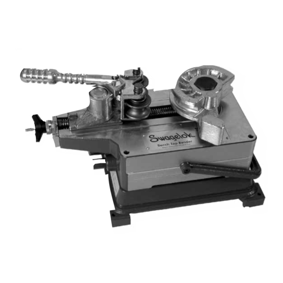
Bench Top Tube Bender
User's Manual
Electric and manual units
■
Bends fractional and metric tubing
■
CE compliant
■
Table of
Contents
Previous
Page
Next
Page
1
2
3
4
5
Advertisement
Chapters
Bench Top Tube Bender
2
Fractional Tubing with Metric Dimensions Continued
34
Table of Contents
Need help?
Do you have a question about the MS-TBE-2 series and is the answer not in the manual?
Ask a question
Questions and answers
Related Manuals for Swagelok MS-TBE-2 series
Construction Equipment Swagelok MS-TBE-1 User Manual
Electric tube bender (16 pages)
Power Tool Swagelok MS-BTB-M series User Manual
Bench top tube bender (44 pages)
Power Tool Swagelok MS-BTB-2 series User Manual
Bench top tube bender (44 pages)
Power Tool Swagelok MS-BTB-1 series User Manual
Bench top tube bender (44 pages)
Power Tool Swagelok TUBE FACING TOOL User Manual
Tube facing tool (21 pages)
Power Tool Swagelok TF72 User Manual
Tube facing tool (20 pages)
Power Tool Swagelok TF16 User Manual
Tube facing tools (28 pages)
This manual is also suitable for:
Ms-btb-m series
Ms-tbe-1 series
Ms-btb-2 series
Ms-btb-1 series
Table of Contents
Print
Rename the bookmark
Delete bookmark?
Delete from my manuals?
Login
Sign In
OR
Sign in with Facebook
Sign in with Google
Upload manual
Upload from disk
Upload from URL


Need help?
Do you have a question about the MS-TBE-2 series and is the answer not in the manual?
Questions and answers