Table of Contents
Advertisement
Quick Links
Advertisement
Table of Contents

Subscribe to Our Youtube Channel
Related Manuals for Swagelok MS-TBE-1


Summary of Contents for Swagelok MS-TBE-1
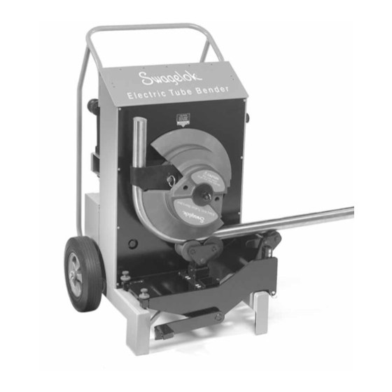
- Page 1 Ele ctr ic Tub e B e n de r Us er ’s M a n u al...
-
Page 2: Table Of Contents
Table of Contents Operator’s Safety Summary............... .3 Grounding and Extension Cord Information . -
Page 3: Operator's Safety Summary
Operator’s Safety Summary READ AND UNDERSTAND THIS MANUAL BEFORE USING BENDER. This device is electrically powered and must be operated in a safe environment to avoid risk of fire, explosion, or electric shock. Grounding and Extension Cord Information • Bender MUST be grounded to guard against electrical shock. It is equipped with a three-wire conductor and three-prong plug to fit a grounded receptacle. -
Page 4: Safety Features
Safety Features Emergency Stop Button Stops rotation of bend shoe andclears all settings. Auto bend function will require reprogramming. Circuit Breaker Disconnects power from outside source. Clears all settings. Receptacle with Cord/Socket Lock Plug in power cord. Tighten screw on cord/ socket lock to secure power cord. -
Page 5: Tube Bender Technical Data
0.095/0.220 0.109/0.188 — 3.0/5.0 ➀ See the Swagelok Tubing Data catalog for suggested tubing wall thickness for use with Swagelok tube fittings. READ AND BECOME FAMILIAR WITH OPERATING INSTRUCTIONS BEFORE BENDING TUBING! This bender can be used in the vertical or horizontal position. -
Page 6: Tube Bender Components
Tube Bender Components Roller Towers Tube Clamps Bend Shoe Removable Tail Roller Bend Shoe Retaining Pin Roller Tower Fixed Tail Roller Roller Bridge Opening Adjustment Screws Handle Lock Bridge Error Message Digital Display Pendant An “E1” in pendant display indicates that the motor has stopped. -
Page 7: Assembling Components
Assembling Components Up Position 1. Select and install proper tail rollers. To bend 1 1/2 in. (38 mm) OD 1 1/2 in. (38 mm) tubing, use the fixed tail roller in the up position. For 2 in. (50 mm) OD tubing, use the fixed tail roller in the down position. -
Page 8: Tubing Layout
Tubing Layout With this bender, you can form single, offset, and other bends. This section contains information for measuring and First 90 Bend.eps NOTE: Make all marks 360° around the tubing. marking the tubing prior to bending. Measurement Length Measurement Mark Reference Bend... -
Page 9: Multiple 90° Bends (Premeasure Method)
Multiple 90° Bends The Premeasure Method 1. Follow Steps 1 to 3 for a Single 90° Bend. (See page 8.) 2. From the reference mark at the end of the tubing, measure the desired length for the second bend and make a measurement mark. -
Page 10: Making Offset Bends
Making Offset Bends NOTE: Make all marks 360° around the tubing. 1. Make a reference mark at the end of the tubing from which your measurement begins. 2. From the reference mark at the end of the tubing, measure the desired length for the bend. Make a measurement mark on the tubing. -
Page 11: Springback
Springback Bending the tubing approximately 3° beyond the desired angle is necessary to compensate for tubing springback. NOTE: This is an approximate value. Tubing springback characteristics differ due to size, wall thickness, and material. WARNING! MOVING PARTS. Bending Figure 5 1 1/4 and 2 in. (32 and 50 mm) Reference Notch 1. Press the BEND or UNLOAD function key. Rotate the bend shoe until the proper reference notch on the bend shoe is aligned with the pointer on the faceplate. (See Figures 5 and 6.) Note the difference in appearance of the bend shoe in each figure. -
Page 12: Bending Using Auto Bend
Bending Using Auto Bend Use the auto bend feature to program a bend angle into the bender’s memory for applications where a single bend angle must be repeated. NOTE: A bend setting will be stored in memory until power is disconnected or a new bend is set. -
Page 13: Roller Adjustment Screws
Roller Adjustment Screws The two roller adjustment screws on the left side of the bender (see Figure 10) change the pressure applied to the tubing. The factory setting (as viewed from the front) for these screws is the gap measured between the top of the bender frame leg and the bottom of the screw blocks. -
Page 14: Maintenance
Maintenance If this bender is subjected to flooding, severe impact, fire, or other extreme conditions, it should be inspected thoroughly by a trained technician before use. Front Chain The front chain requires no routine adjustment. However, it will stretch slightly after making the first 10 to 20 bends of 1 1/2 or 2 in.; or 38 or 50 mm OD heavy wall tubing. If there is any slack in the chain: Figure 12 1. - Page 15 – 15 –...
-
Page 16: Warranty Information
Warranty Information Swagelok products are backed by The Swagelok Limited Lifetime Warranty. For a copy, visit swagelok.com or contact your authorized Swagelok representative. Swagelok—TM Swagelok Company ©1999, 2002, 2004 Swagelok Company Printed in U.S.A. December 2004, R5 MS-13-138...
Need help?
Do you have a question about the MS-TBE-1 and is the answer not in the manual?
Questions and answers