Table of Contents
Advertisement
Installation & Instruction Manual
Installation & Instruction Manual
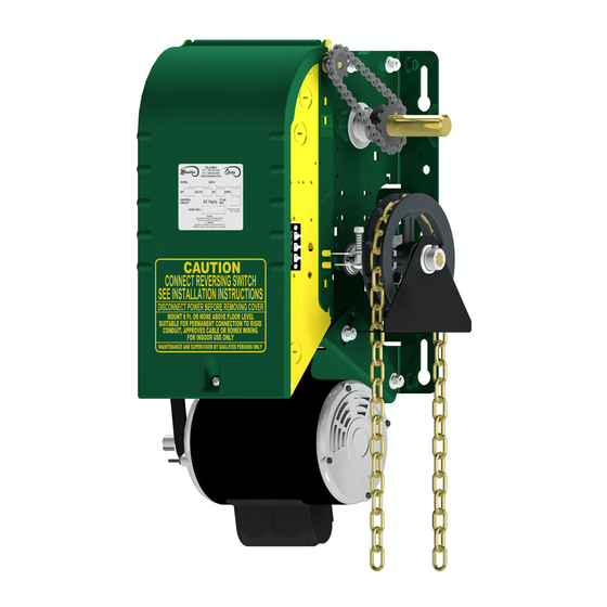
Commercial & Industrial Heavy Duty Jackshaft Operator
Commercial & Industrial Heavy Duty Jackshaft Operator
(For sectional doors, rolling doors and grilles)
(For sectional doors, rolling doors and grilles)
Opera-H
Opera-H
Opera-HJ
Opera-HJ
Opera-J
Opera-J
Opera-SH
Opera-SH
(OPH)
(OPH)
(OHJ)
(OHJ)
(OPJ)
(OPJ)
(OSH)
(OSH)
Electro-Mechanical Control
Electro-Mechanical Control
READ AND FOLLOW ALL INSTRUCTIONS.
SAVE THESE INSTRUCTIONS.
GIVE TO END-USER.
Serial #
Model #
Wiring Diagram #
Project #/Name
Door #/Name
For technical support, please call 1-800-361-2260 or visit
www.manaras.com
for more information
Advertisement
Table of Contents


Need help?
Do you have a question about the Opera-H and is the answer not in the manual?
Questions and answers