Table of Contents
Advertisement
I
n
s
t
a
l
l
a
t
i
o
n
&
I
n
s
t
r
u
c
t
i
o
n
M
a
n
u
a
l
I
n
s
t
a
l
l
a
t
i
o
n
&
I
n
s
t
r
u
c
t
i
o
n
M
a
n
u
a
l
O
p
e
r
a
-
M
J
O
p
e
r
a
-
M
J
O
p
e
r
a
-
M
H
O
p
e
r
a
-
M
H
Note: Read this manual carefully before
installing the operator and place this installation
manual in an accessible place near the
operator. For future reference record:
Model #
Date
Wiring Diagram #
Serial #
®
Project No.
Project Name
Door No. #
TM
Advertisement
Table of Contents

Related Manuals for Manaras Opera-MH


Summary of Contents for Manaras Opera-MH
- Page 1 & & Note: Read this manual carefully before installing the operator and place this installation manual in an accessible place near the operator. For future reference record: Model # Date Wiring Diagram # Serial # ® Project No. Project Name Door No.
- Page 2 IMPORTANT SAFETY INSTRUCTIONS WARNING TO REDUCE THE RISK OF SEVERE INJURY OR DEATH, READ AND FOLLOW ALL INSTRUCTIONS 1. Never allow children to operate or play with or near door. 2. Check to see that the operator is correct for the type, size of door and frequency of use per the operator specifications.
-
Page 3: Table Of Contents
OPTIONAL CONTROL ACCESSORIES ....................15 CONNECTION OF SAFETY EDGE......................16 CLUTCH ADJUSTMENT .........................16 OPERATOR START-UP AND TESTING GUIDE ..................18 TROUBLESHOOTING GUIDE ......................18-20 SCHEDULED MAINTENANCE........................21 Opera-MH exploded view.........................22 Opera-MJ exploded view .........................23 Opera-MH/MJ STANDARD ELECTRICAL DIAGRAM ................24 Opera-MH/MJ STANDARD ELECTRICAL DIAGRAM………………………………………………………..25 WARRANTY……………………………………………………………………………………………………….26 NOTES ..............................27... -
Page 4: General Parts & Specifications
Intermittent duty ½ Horsepower OPERATOR OUTPUT SPEED……… 39 RPM NET WEIGHT Operator only)……… 71 Lbs (33 Kg) for Opera-MH and 61lbs (28 Kg) for Opera-MJ STANDARD WIRING TYPE………… C2-momentary contact to open and stop and constant pressure to close DIMENSIONS (Opera-MH) -
Page 5: Product Application
TABLE 1 STANDARD PARTS LIST FOR OPERA JACKSHAFT OPERATOR PART # DESCRIPTION Pocket wheel hand chain (2X door shaft less 4 ft. (1.2m)) for Opera-MH or disconnect chain (14’) for Opera-MJ 3-button open/close/stop push-button station #41 connecting link #41 roller chain x 4'(1.2m) or x 5’ when sprocket is 42 teeth or more. -
Page 6: Installation
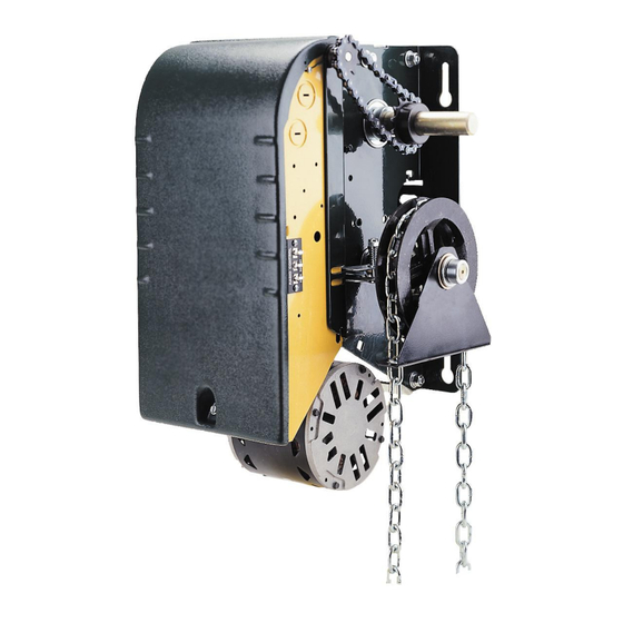
The Opera-MH comes with a chain hoist located on the right of the operator. If handing requires the chain hoist to be on the left (rolling doors, left operator hood mounting for ex.), it must be requested at the time of ordering. - Page 7 INSTALLATION OF OPERA OPERATOR IMPORTANT NOTE: THIS OPERATOR MUST BE INSTALLED A MINIMUM OF 8 FT. (2.4 m) ABOVE FLOOR. The OPERA has two sets of mounting holes: outside the frame for wall mounting and inside the frame for hood mounting. To open the control box cover, loosen the screw at the base of the cover.
- Page 8 Figure 6 Mounting dimensions for wall or hood CAUTION MAKE CERTAIN THAT OPERATOR IS PERFECTLY ALIGNED WITH DOOR SHAFT OTHERWISE DAMAGE CAN OCCUR Place the driven sprocket on the door shaft loosely and align it with the drive sprocket of the operator.
- Page 9 Opera-MH: run hand chain through the pocket wheel and through the chain guide outside the frame (Figure 10A), allow both ends to hang down toward the ground and cut hand chain, if necessary, so that both ends are approximately 2 feet (0.6 m) from floor.
-
Page 10: Limit Switches
LIMIT SWITCHES WARNING TO AVOID THE DANGER OF POSSIBLE DAMAGE TO THE DOOR AND OPERATOR, TRAVELLING CAMS MUST BE ADJUSTED TO THEIR APPROXIMATE POSITIONS BEFORE MANUALLY OPERATING THE DOOR OR BEFORE APPLYING POWER TO THE OPERATOR. There are 4 limit switches. Two are used as end of travel, one is for radio-control or one-button operation and one is for reversing devices. -
Page 11: Suggested Wire Size
ADJUSTMENT OF LIMIT SWITCHES This unit is provided with ACCU-CAM ® for precise and quick one-handed adjustment feature. Pull the traveling cam retaining bracket on desired side to adjust cam position Figure 12 Adjusting the limit cams MINIMUM SUGGESTED WIRE SIZE FOR CONTROL CIRCUIT The control circuit operates at 24 VAC. -
Page 12: Wiring Of An Opera
4.5 WIRING OF THE OPERA OPERATOR Do NOT connect any accessory controls until the limit switch adjustments have been completed and the operator is functioning properly. Refer to the electrical diagrams on pages 24, the wiring specifications in TABLE 2 and the terminal input connections of Figure 19. - Page 13 A 3 button push-button station (open/close/stop) can be wired to terminals 2, 3, 4 and 5. Two push-button stations can be wired to these same terminals by following the wiring diagrams on pages 24. Stop Open Close Figure 15 Three button push-button station 3.
-
Page 14: B2/C2 Wiring
B2 AND C2 WIRING For Safety reasons Manaras has decided to propose its standard operators with C2 wiring. B2 can be set very easily by moving wires. This operation can be performed by the installer as shown below or by Manaras when requested on the order. -
Page 15: Optional Control Accessories
5.1. OPTIONAL CONTROL ACCESSORIES Radio Controls: Consists of a radio receiver unit and remote transmitters. These controls consist of an RF signal being emitted on a "pulse" basis to a mated receiver tuned to the same "pulse" rate. Once the receiver accepts the code, a relay is activated closing a set of contacts. -
Page 16: Connection Of Safety Edge
5.2. CONNECTION OF A REVERSING EDGE DEVICE IMPORTANT NOTE: If the door is controlled by any device other than a constant pressure push- button station, a reversing edge must be connected. CAUTION Connect reversing device appropriate to installation. Connection and installation of a reversing edge device is provided with the edge (see also Figure 20). Any such device that uses a normally open contact may be connected to terminals 3 and 6 on the low voltage terminal block (Figure 18). - Page 17 ADJUSTMENT AND MANUAL OPERATION OF OPERA-MH OPERATOR Opera-MH (designed with Hoist-a-Matic ® self engaging hoist system) The Opera-MH operator is equipped with an automatic emergency chain hoist disconnect mechanism to operate the door manually, no floor disconnect is required. In one simple step Control circuit interrupted.
-
Page 18: Operator Start-Up And Testing Guide
5.5. MANUAL OPERATION OF OPERA-MJ Pull on the disconnect chain until feel a resistance. Engage the chain in the chain keeper. The door is disconnected from the electrical motor and ready to be manually operated. Just make free the disconnect chain from the chain keeper to ‘’reconnect’’ the operator and return the standard electrical operation. -
Page 19: Troubleshooting Guide
Pull on chain slightly in each direction in order to activated the disconnect switch disengage the chain hoist and return the operator to (Opera-MH) electrical operation. Check switch otherwise Allow the operator to cool for 20 minutes before using it Motor has overheated and the again. - Page 20 SYMPTOM PROBABLE CAUSE SUGGESTED ACTION “advanced close” limit switch is not When door closes it The "advanced close" limit switch needs to be adjusted sufficiently advanced. Reversing reverses to fully just slightly ahead of the end of travel "closed" limit edge is not disabled causing door open.
-
Page 21: Scheduled Maintenance
7. SCHEDULED MAINTENANCE Maintenance and supervision should be performed by qualified persons only. Inspection and service should be performed anytime a malfunction is observed or suspected. WARNING WHEN SERVICING - ALWAYS DISCONNECT OPERATOR FROM POWER SUPPLY 7.1 MECHANICAL The door area should always be kept clear of dirt, rocks or any other substance to insure proper operation. EVERY 3 - Check and adjust the clutch, if necessary. -
Page 24: Opera-Mh/Mj Standard Electrical Diagram
8.3. Opera-MH/MJ standard wiring diagram... -
Page 25: Opera-Mh/Mj Standard Electrical Diagram
8.4. Opera-MJ wiring diagram with solenoid brake... -
Page 26: Warranty
Manaras’ only obligation shall be to repair or replace defective equipment which does not conform to the warranty. Manaras shall not be liable for any injury, loss or damage, direct or consequential, arising out of the inability to use the equipment. Before using, Buyer and/or the ultimate User shall determine the suitability of the product for its intended use, and User assumes all risks and liability in connection therewith. -
Page 27: Notes
NOTES... - Page 28 OPERA Reg. T.M. of 9141-0720 Québec Inc. BOOK057 REV 4 - 2010/08/29...
Need help?
Do you have a question about the Opera-MH and is the answer not in the manual?
Questions and answers