Table of Contents
Advertisement
Quick Links
Advertisement
Table of Contents

Subscribe to Our Youtube Channel
Related Manuals for Smart Tweezers ST5


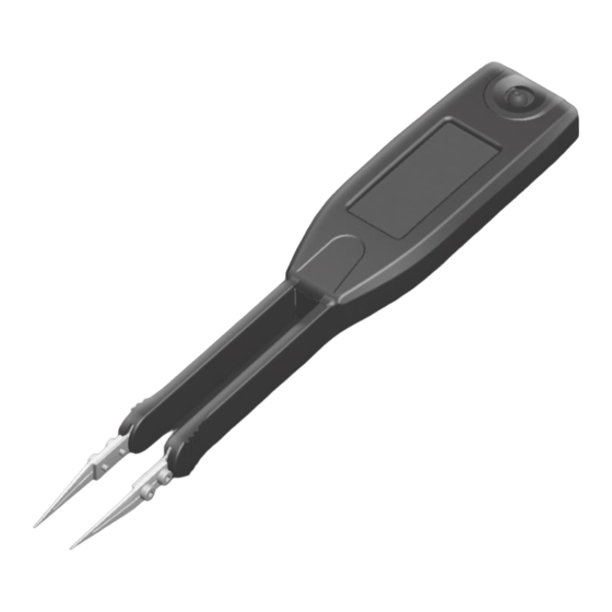
Summary of Contents for Smart Tweezers ST5
- Page 1 SmartTweezers_Manual_03.8.indd 2-3 10/14/2011 2:04:07 PM...
-
Page 2: Table Of Contents
TABLE OF CONTENTS Notice Warranty Safety Precautions Getting Started Overview Controls Power On Menu Structures And Functions Measurement Features Measuring Resistance Measuring Capacitance Measuring Inductance Maintenance Labelling & Verification Requirements Appendix A. Specifications Appendix B. Default Settings Appendix C. Accuracy Specification SmartTweezers_Manual_03.8.indd 5 10/14/2011 2:04:07 PM... -
Page 3: Notice
To The Jog dial buTTon, slide swiTch and reseT swiTch; elecTrical damage of The producT due To high volTage or improper baTTery Type. To avoid possible damage to Smart Tweezers or to the equipment under test, follow these guidelines: The design and implemenTaTion of any circuiT based on This producT is The sole responsibiliTy of The cusTomer. -
Page 4: Getting Started
SMT components with size down to 0201. output of AI provides a signal proportional to the current, I*Ri. In actual use Smart Tweezers provides more accurate results than Voltage across the DUT is measured by a separate signal path most of the benchtop LCR meters due to small and very predictable (amplifier AU), thus providing a pseudo 4-wire Kelvin connection. -
Page 5: Controls
25V parts and 1.0V for < 16V parts). Note: Use the largest voltage possible for the best SNR and accuracy. The ST5 provides three measurement ranges (R1-R3). Each of the three ranges has the source impedance of approximately the mid-scale impedance. The table below specifies the Quick Controls impedance ranges for each of the measurement ranges. -
Page 6: Power On
It shows the dominant impedance parameter reading typically with 5 digits displayed. POWER-ON - To turn the Smart Tweezers ON, SECONDARY DISPLAY: The Secondary Display is located just above the press the Navigation Controller. - Page 7 SmartTweezers_Manual_03.8.indd 7-8 10/14/2011 2:04:08 PM...
-
Page 8: Menu Structures And Functions
This section describes menu structure and device parameters restore measurement parameters to the default state using Autoset. setting. Smart Tweezers menu system contains • Select AUTOSET to reset parameters to the default settings. • Main menu — main menu items •... - Page 9 The mode could be used for locating shorted part of a circuit e.g. on a PCB. SYSTEM MENU System menu is used to access system settings and functions. DISPLAY MENU SOUNd mENU Display menu is used to change display’s set tings •...
- Page 10 BATTERY The Mode menu is used to set the measurement mode. Select RES, IND, CAP, IMP or ESR menu items to measure desirable component or parameter as Resistance, Inductance, Capacitance, Impedance and ESR accordingly. For automatic measurement select AUTO (default).. AUTO MODE: Select AUTO mode (AM sign appears at the left bottom corner of display) for automatic measurement of inductance, capacitance or resistance.
- Page 11 RANGE MENU SETTING MENU Use this menu to set desirable source impedance range. Default value is auto-ranging (AUTO). Note: Auto-ranging procedure starts from R2 (1kOhm) Use th s menu to set spec fic measurement parameter. LEVEL MENU TEST FREQUENCY MENU Use this menu to set desired test frequency.
- Page 12 • Enter the NULL menu and select SET Example 1: Nulling test leads for small resistance measurement Smart Tweezers will display difference in percent from the reference value and the beeper will beep • 1 time when the component is within the setting tolerance.
- Page 13 SmartTweezers_Manual_03.8.indd 17-18 10/14/2011 2:04:12 PM...
-
Page 14: Measurement Features
Equivalent circuit diagram Parallel (C < 500 pF), Serial( C > 500 pF) In AUTO mode the Smart Tweezers first tries to perform measurement at 1kHz and then automatically selects the best test frequency. The device is capable of measuring capacitance from aproximately 3 pF to 199 μF in AUTO mode. -
Page 15: Measuring Inductance
Optimal test frequency ESR MEASUREMENTS 10 kHz Use the ESR measurement to measure the equivalent series <10000pF resistance of a capacitor independent of its capacitance. 1 kHz 10001pF- 1μF Test frequency 0.1kHz/1 kHz/10kHz There is some small capacitance offset due to capacitance of the tips. The offset depends on the distance between the tips (i.e. -
Page 16: Labelling & Verification Requirements
10 kHz (requires front lead removal). 10000 pF to 1 μF 1 kHz CAUTION: Smart Tweezers repairs should only be performed by an Authorized Service Center or by qualified service personnel. > 1 uF 100 Hz 0.5 μH to 99 μH... -
Page 17: Appendix B. Default Settings
MAXIMUM MEASUREMENT RANGES PHYSICAL SPECIFICATIONS 0.05 Ω to 9.9 MΩ Resistance R: Size 14.0 x 2.5 x 3.0 cm (3.94 x 0.9 x 1.5 in) 0.5 pF to 4999 μF Capacitance C: Weight 53 grams (0.11 lb) Inductance L: 0.5 uH to 999 mH Quality factor Q: 0.001 to 1000 * ENVIRONMENTAL CONDITIONS... -
Page 18: Appendix C. Accuracy Specification
Default settings after AUTOSET command CAPACITANCE SOUND mode: Range Resolution100 Hz 120 Hz 1 kHz 10 kHz DISPAY mode: No change 10 mF 0.001 mF 2.0% + 8 2.0% + 8 Contrast: No change 1000 µF 0.1 µF 0.5% + 5 0.5% + 5 Readings PERIOD: 1 sec...
Need help?
Do you have a question about the ST5 and is the answer not in the manual?
Questions and answers