Table of Contents
Advertisement
Advertisement
Table of Contents

Related Manuals for iPECS LIK50


Summary of Contents for iPECS LIK50
- Page 1 IPECS 50A & 50B Hardware Description & Installation Manual...
- Page 2 - LIK50 Description & Installation 1.2.1 Issue Update Revision History ISSUE DATE DESCRIPTION OF CHANGES JUL. 2008 Initial Release Oct. 2009 Manual is merged Aug. 2010 Changed the new CI (LG-Ericsson) Jun. 2012 1.2.1 Update by W.Smith...
- Page 3 - LIK50 Description & Installation 1.2.1 Issue CD Manual Revision History ISSUE DATE DESCRIPTION OF CHANGES 5 Oct. 2009 Manual is merged Aug. 2010 Changed the new CI (LG-Ericsson)
-
Page 4: Regulatory Information
The local telephone company may make changes in its communications facilities or procedures. If these changes could reasonably be expected to affect the use of iPECS-LIK50 or compatibility with the network, the telephone company is required to give advanced written notice to the user, allowing the user to take appropriate steps to maintain telephone service. -
Page 5: Table Of Contents
Issue Table Of Contents 1. Introduction....................1 Overview ......................... 1 Hardware Components ................... 5 2. Hardware Description................6 iPECS-LIK50 ..................... 6 2.1.1 LIK-MFIM50 (Multi-Function Interface gateway Module 50)....6 2.1.2 AD/DC adapter MFIM50 Modules ....10 LIP Phones & Terminals..................11 2.2.1... - Page 6 - LIK50 Description & Installation 1.2.1 Issue 4.3.3 1U-Rack Mount Bracket Installation ............29 Installation ......................31 4.4.1 LIK-MFIM50A Installation................. 31 4.4.2 LIK-MFIM50B Installation................. 35 4.4.3 ................38 4.4.4 General Installation ..................41 4.4.4.1 Miscellaneous Connections .................. 41 4.4.4.2 Telephony (FXS/FXO) Connections..............41 4.4.4.3...
-
Page 7: Introduction
VOIP (H323/SIP), VSF, USB, two FXS and two 10/100 Base- T Ethernet ports in a module, which connects to the public and private VoIP networks. These models work with existing iPECS gateways and LIP Phones, which provide the user simple access to the many features and functions of the iPECS. - Page 8 The reliability, extensive feature content, the ability to support present and future applications with the iPECS Feature Server and the capability to use an array of modules and instruments, permit the iPECS to be tailored to meet the short and long-term needs of the most demanding customer requirements.
- Page 9 - LIK50 Description & Installation 1.2.1 Issue Figure 1.1-2 below is a diagram of the system, terminals and applications available with iPECS- LIK50B. Figure 1.1-2 iPECS-LIK50B Structure...
- Page 10 - LIK50 Description & Installation 1.2.1 Issue Figure 1.1-23 NA. . Figure 1.1-3 NA.
-
Page 11: Hardware Components
Issue 1.2 H ARDWARE OMPONENTS Table 1.2-1 provides a description of the hardware components that make-up iPECS-LIK50 . All of these Modules and terminals are connected over a 10/100 Base-T Ethernet LAN. Table 1.2-1 Modules and Terminals of iPECS-LIK50 ITEM... -
Page 12: Hardware Description
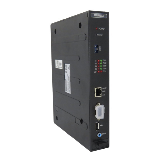
2.1.1 LIK-MFIM50 (Multi-Function Interface gateway Module 50) Multi-Function Interface gateway Modules (LIK-MFIM50A, LIK-MFIM50B), which are the main controller for iPECS-LIK50 and employ the iPECS protocol, extend telephony resources and call processing to the iPECS modules and terminals. LIK-MFIM50A incorporates CO line interfaces for CO/PBX Loop Start Line MFIM50B incorporates ISDN Basic Rate Interface (2B+D). - Page 13 270 minutes. Each MFIM50 has a 10/100 Base-T Ethernet interface, the “LAN” RJ-45 type connector, which is to interface the iPECS call server features and functions. The Ethernet port incorporate auto MDI, MDIX switching, therefore, both straight and cross cables can be used.
- Page 14 - LIK50 Description & Installation 1.2.1 Issue On the rear panel, MFIM50A has: Eight (8) RJ-45 female connectors; for 4 FXO ports, 2 FXS ports, BGM/MOH and External Page outputs, Control Relay input and Alarm Input, Ground Lug, Power jack for the AC/DC adapter; see section 2.1.3.
- Page 15 - LIK50 Description & Installation 1.2.1 Issue This page intentionally blank.
-
Page 16: Ad/Dc Adapter Mfim50 Modules
- LIK50 Description & Installation 1.2.1 Issue 2.1.2 AD/DC adapter for LIK-MFIM50 Modules LIK-MFIM50A/B, Figure 2.1.3-1, are packaged with an AC/DC adapter. The adapter is supplied with a two (2) meter (six (6) foot) AC cord terminated with the nationally relevant AC blade type. -
Page 17: Lip Phones & Terminals
& T HONES ERMINALS iPECS-LIK50 works with a number of telephone types including standard SLTs, VoIP phones (SIP or H.323 v3) and the LIP Phones. The LIP Phones are available in several models as shown in Table 2.2-1. Table 2.2-1 LIP Phones... - Page 18 - LIK50 Description & Installation 1.2.1 Issue terminal. The ports are connected to an intelligent 10/100Base-T switch, which gives LAN access to the data device while giving priority to voice packets. The LIP-8000 series DSS Consoles are used to expand the number of flexible buttons available to a user by 12 or 48 buttons and are connected to the LIP-8000 phone via a flat cable.
- Page 19 - LIK50 Description & Installation 1.2.1 Issue In addition, the LIP-8012D, 8024D and 8040L include 3 soft buttons. The function of these buttons is interactive and shown in the lower line of the LCD. These models also incorporate a full duplex speakerphone.
- Page 20 - LIK50 Description & Installation 1.2.1 Issue Figure 2.2.1-2 LIP-8004D Figure 2.2.1-2 LIP-8012D Figure 2.2.1-3 LIP-8024D...
- Page 21 - LIK50 Description & Installation 1.2.1 Issue Figure 2.2.1-4 LIP-8040L Figure 2.2.1-5 LIP-8012DSS...
- Page 22 - LIK50 Description & Installation 1.2.1 Issue Figure 2.2.1-6 LIP-8012LSS Figure 2.2.1-7 LIP-8048DSS...
-
Page 23: Lip-7000 Series Phones
- LIK50 Description & Installation 1.2.1 Issue 2.2.2 LIP-7000 series Phones The LIP-7000 series IP phones are available in five (5) models as well as a matching DSS/BLF Console. Models available include: LIP-7004N, 4-button non-display LIP-7008D, 8-button 2-line display LIP-7016D, 16-button 3-line display... - Page 24 - LIK50 Description & Installation 1.2.1 Issue LIP-7016D, 7024D, & 7024LD Hold/Save Volume Control Speed Trans/Pgm Call Back Navigation buttons In addition, the LIP-7016, 7024D and 7024LD include 3 Soft buttons. The function of these buttons is interactive and shown in the lower line of the LCD.
- Page 25 - LIK50 Description & Installation 1.2.1 Issue Figure 2.2.2-3 LIP-7016D Figure 2.2.2-4 LIP-7024D Figure 2.2.2-5 LIP-7024LD Figure 2.2.2-6 7000 Series Phones Wall Mount Bracket...
-
Page 26: Ac/Dc Adapter For Lip-Phones & Console
Wall mounted individually using the Wall Mount Holder, or 19” rack mounted individually using the 1U-Rack Mount Bracket. The following paragraphs describe the mounting hardware MFIM50/B . Refer to iPECS Description and Installation manual for instructions on installation of additional modules, if required. -
Page 27: Whld (Wall Mount Holder)
- LIK50 Description & Installation 1.2.1 Issue 2.3.2 WHLD (Wall mount HoLDer) LIK-MFIM50A/B can be individually wall mounted in the WHLD (module Wall Mount Holder), shown in Figure 2.3.2-1. The WHLD provides wall mounting for a single module. Figure 2.3.2-1 Module Wall Mount Holder 2.3.3 1URMB (1U Rack Mount Bracket) -
Page 28: Software Components
Issue 2.4 S OFTWARE OMPONENTS iPECS software comes pre-loaded in the various system modules. In addition, application and services software have been developed to expand and enhance iPECS functionality. Applications and Services offered include: iPECS Phontage PC SoftPhone iPECS Phontage PDA SoftPhone iPECS TSP/MSP - TAPI 3.1... -
Page 29: System Specifications
- LIK50 Description & Installation 1.2.1 Issue 3. S YSTEM PECIFICATIONS 3.1 S YSTEM APACITY Table 3.1-1 System Capacities CAPACITY LIK-MFIM50A LIK-MFIM50B LIK- System Capacity Stations PSTN/ISDN circuits*2 ( Basic: 4 PSTN +VoIP) ( Basic: 4 ISDN-BRI +VoIP) (Basic: 5 VoIP) Max. -
Page 30: Dimension And Weight
- LIK50 Description & Installation 1.2.1 Issue 3.2 D IMENSION AND EIGHT Table 3.2-1 Dimensions and Weight ITEM HEIGHT WIDTH DEPTH WEIGHT (mm/in) (mm/in) (mm/in) (kg/lbs) LIK-MFIM50A/B 230/9.1 38.8/1.5 194.5/7.7 0.7/1.54 1U RMB 38.3/1.5 482.6/19 183.27.2 2/4.4 DHLD * 146/5.7 111.5/4.4*... -
Page 31: Interface Specifications
- LIK50 Description & Installation 1.2.1 Issue 3.4.2 Interface Specifications Table 3.4.2-1 Interfaces Interfaces Specifications Ethernet RJ-45 unshielded Connector Ethernet 10/100 BASE-T Maximum Wiring Distance 100m / 0.328Kft Connector USB Female Plug type A Host V 1.1 Mode RS-232 Connector... -
Page 32: Pstn Specification
- LIK50 Description & Installation 1.2.1 Issue 3.5 PSTN S PECIFICATION Table 3.5-1 PSTN Specifications ITEM SPECIFICATION Ring Detect Sensitivity Min 20 Vrms @ 16~67 Hz DTMF Dialing Less than +/-1.8% - Frequency Deviation - Signal Rise Time Max. 5ms - Tone Duration, on time Min. -
Page 33: Installation
4. I NSTALLATION 4.1 O VERVIEW As with any sophisticated communications device, installation of iPECS-LIK50 require the care and forethought of a competent technician. Recommended installation proceeds in 6 major steps: Site Preparation Equipment verification Cabinet/Desk/Wall Mount Holder installation, as required... -
Page 34: Verify Equipment On-Site
- LIK50 Description & Installation 1.2.1 Issue The site should be away from radio transmitting equipment, arc-welding devices, copy machines, and other electrical equipment capable of generating high levels of electrical interference. The system should be protected from flooding and heavy machinery as well as excessive dust and vibration. -
Page 35: Wall Mount Holder Installation
- LIK50 Description & Installation 1.2.1 Issue 4.3.2 Wall Mount Holder Installation The Module Wall Mount Holder will house a single Module. To install, refer to Figure 4.3.2-1 and instructions below: Place the Wall Mount Holder in position and mark two (2) holes over a wall stud. - Page 36 - LIK50 Description & Installation 1.2.1 Issue Figure 4.3.3-1 1URMB Adapter Installation 2. Install LIK-MFIM50A/B Module into the 1U-RMB and connect the adapter plug, refer to Figure 4.3.3-2. Slide the Module into the 1U-RMB. Connect the adapter DC plug to the LIK-MFIM50A/B .
-
Page 37: Installation
- LIK50 Description & Installation 1.2.1 Issue Wire the Module as described in section 4.4. Connect the AC cable to the adapter and wall outlet to power the Module. Figure 4.3.3-3 Installing 1URMB on the Rack 4.4 I NSTALLATION 4.4.1 LIK-MFIM50A Installation LIK-MFIM50A can be installed in the Desk Mount Holder, Wall Mount Holder and 1U Rack Mount Bracket. - Page 38 This is useful when multiple systems may be connected to the same LAN. For details on gateway Module and terminal registration, refer to the iPECS Admin & Program Manual. The system database is initialized based on switch position 4. In the ON position, the system will load default values in the system database when power is applied to LIK-MFIM50A or the Reset button is pressed.
- Page 39 - LIK50 Description & Installation 1.2.1 Issue PFT (Power Failure Transfer) In the event of a power failure, LIK-MFIM50A will connect “FXO port 1” directly to the telephone terminal on “FXS port 1” using the internal PFT relay. CMU (Call Metering Unit) LIK-MFIM50A supports call metering with installation of an optional CMU module.
- Page 40 - LIK50 Description & Installation 1.2.1 Issue Figure 4.4.1-2 LAN Connection and Indicators in the front s The eight (8) RJ-45 connectors on the rear panel of LIK-MFIM50A are terminated for miscellaneous functions, FXO Line, and FXS devices. The Miscellaneous and telephony connectors are terminated as shown in 4.4.4.1 and section 4.4.4.2, respectively.
-
Page 41: Lik-Mfim50B Installation
- LIK50 Description & Installation 1.2.1 Issue 4.4.2 LIK-MFIM50B Installation LIK-MFIM50B can be installed anywhere in 1U Data Rack Holder, Desk Mount Holder or Wall Mount Holder. LIK-MFIM50B contains a long life Lithium battery, which protects the memory and real-time clock in the event of a power failure. - Page 42 This is useful when multiple systems may be connected to the same LAN. For details on gateway Module and terminal registration refer to the iPECS Admin & Program Manual. The system database is initialized based on switch position 4. In the ON position the system will load default values in the system database when power is applied to LIK-MFIM50B or the Reset button is pressed.
- Page 43 - LIK50 Description & Installation 1.2.1 Issue The eight (8) RJ-45 connectors on the rear panel of LIK-MFIM50B are terminated for miscellaneous functions, BRI Lines, and FXS devices. The Miscellaneous, BRI and telephony connectors are terminated as shown in section 4.4.4.1, section 4.4.4.3 and section 4.4.4.2, respectively.
- Page 44 - LIK50 Description & Installation 1.2.1 Issue 4.4.3 Bl a nk BLANK...
- Page 45 - LIK50 Description & Installation 1.2.1 Issue BLANK...
- Page 46 - LIK50 Description & Installation 1.2.1 Issue BLANK...
-
Page 47: General Installation
- LIK50 Description & Installation 1.2.1 Issue 4.4.4 General Installation The following paragraphs provide general and common installation and wiring practices and procedures for both LIK-MFIM50A and LIK-MFIM50B. Procedures such as LAN wiring are common for all LAN ports and are discussed here. -
Page 48: Bri Line Connections
- LIK50 Description & Installation 1.2.1 Issue 4.4.4.3 BRI Line Connections BRI Line connectors should be wired to the telephone company termination point (‘T” Mode). The connector pin assignments for the RJ-45 type jacks of BRI Ports are shown in Figure 4.4.4.3-1. -
Page 49: Lan Wiring Structure
EIA 568A (MDIX) Figure 4.4.4.4-1 Pin Assignments of LAN Connector (RJ-45) 4.4.4.5 LAN Wiring Structure The LAN wiring architecture used for connecting iPECS Modules to the LAN is dependent upon several factors including: Shared or iPECS only LAN infrastructure External VoIP calling requirements... - Page 50 Console requires a single port and the LIK-MFIM50A/B will require a single port. Thus, 24 station system would require a total of 25 ports (LIK-MFIM50A = 1 port, and 24 LIP Phones = 24 ports), and would be structured as in the Figure 4.4.4.5-1. Figure 4.4.4.5-1 iPECS LAN Wiring...
-
Page 51: Rs-232 Connection
LIK-MFIM50A/B are set-up for 8-bits, no parity, and one (1) stop bit running at 115,200 bps. To modify the speed and other settings, refer to the iPECS Admin & Program Manual. The RS-232 connectors MFIM50A/B are terminated in a Data Communications Equipment (DCE) -
Page 52: Module Grounding
- LIK50 Description & Installation 1.2.1 Issue LIK MODULE DB-9 RS-232 TERMINATIONS TYPICAL TERMINAL DB-25 RS-232 TERMINATIONS Designation. Function Transmitted Data Received Data Request To Send Clear To Send Data Terminal Ready Data Set Ready Figure 4.4.4.6-1 RS-232 DB-9 Pin-outs 4.4.4.7 Module Grounding... -
Page 53: Module Installation Sequence
Although the in the database can be changed, connecting the gateway SEQUENCE NUMBER Modules to the iPECS in the desired sequence based on type of Module is recommended. The Module can be easily established at installation by controlling the order of SEQUENCE NUMBER connection of the Module’s LAN port to the system. -
Page 54: Lip Phone Installation
- LIK50 Description & Installation 1.2.1 Issue 4.5 LIP P HONE NSTALLATION LIP Phones and Consoles can be connected to any standard 10/100 Base-T Ethernet switch port. When connected to an 802.3af compliant switch port, such as the POE8, the LIP Phone and LIP- 7000 series consoles can derive power from the Ethernet port. - Page 55 - LIK50 Description & Installation 1.2.1 Issue Slide the LIP-8000 phone over the screws and assure the phone is secure. Note it may be necessary to remove the phone and tighten or loosen the screws for a secure mounting. Remove the Handset hook from the phone as shown in the figures below. Reverse the hook and re-install in the LIP-8000 phone so that the hook catches the groove in the handset receiver.
- Page 56 - LIK50 Description & Installation 1.2.1 Issue Keep in mind the following conditions when installing LIP-8000 DSS consoles. 1) The AC/DC adapter must be used for LIP-8048DSS. 2) Up to two (2) LIP-8012LSS and/or LIP-8012DSS can be installed with LIP-8000 Phone.
- Page 57 - LIK50 Description & Installation 1.2.1 Issue Figure 4.5-4 LIP-8000 DSS Installation (12DSS + 12LSS) Figure 4.5-5 LIP-8000 DSS Installation (12DSS + 12LSS+48DSS)
- Page 58 - LIK50 Description & Installation 1.2.1 Issue The LIP-24D/DH or LIP 7000 Phones can be mounted on the wall using the appropriate Wall Mount Kit. The Wall Mount Kit is installed as described below and shown in Figure 4.5-6. Using the Wall Bracket, mark and drill two (2) 7 mm holes for the plastic wall anchors provided.
-
Page 59: Appendix. Useful Information
- LIK50 Description & Installation 1.2.1 Issue PPENDIX SEFUL NFORMATION Open Source Software Notice This following GPL (General Public License) software used in this product are subject to the GPL License Agreements. You can obtain a copy of the GPL licenses from LG-Ericsson Web Site (http://www.lgericsson.com).
Need help?
Do you have a question about the LIK50 and is the answer not in the manual?
Questions and answers