Table of Contents
Advertisement
Order No.Ref0902S006V0
This service information is designed for experienced repair technicians
only and is not designed for use by the general public. It does not contain
warnings and cautions to advice non-technical individuals of potential
dangers in attempting to service a product. Product powered by electricity
should by serviced or repaired only by experienced professional
technicians. Any attempt to service or repair the product or products dealt
with in this service information by anyone else could result in serious injury
or death.
SERVICE MANUAL
WARNING
◎2009(HAIER ELECTRICAL APPLIANCES COR. LTD)
All right reserved. Unauthorized copying and distribution is a violation of law。
MODEL:
A2FE635CFJRU
C2FE636CWJRU
C2FE636CFJRU
C2FE636CSJRU
A2FE637CXJRU
C2FE637CXJRU
Advertisement
Table of Contents

Subscribe to Our Youtube Channel
Related Manuals for Haier A2FE635CFJRU


Summary of Contents for Haier A2FE635CFJRU
- Page 1 Any attempt to service or repair the product or products dealt with in this service information by anyone else could result in serious injury or death. ◎2009(HAIER ELECTRICAL APPLIANCES COR. LTD) All right reserved. Unauthorized copying and distribution is a violation of law。...
-
Page 2: Table Of Contents
SERVICE MANUAL Issue Rev. Model: Contents Table of Contents ··········································································································· 1 1. General Information ·································································································· 4 1-1.General guidelines ······························································································ 1-2. Important notice·································································································· 1-3. How to read this Service Manual ········································································ 2. Product Feature ········································································································ 7 2-1. Specifications ·········································································································· 2-2. External views ·········································································································... - Page 3 SERVICE MANUAL Issue Rev. Model: 6-4. Electromagnetic valve ························································································ 7. System flow principle ······························································································· 34 7-1. Refrigeration flow chart ····················································································· 7-2. Refrigeration flow scenograph ·········································································· 7-3. Air flow scenograph ·························································································· 7-4. Water supply flow scenograph ·········································································· 8. Circuit diagram·········································································································· 37 8-1.
-
Page 4: General Information
SERVICE MANUAL Issue Rev. Model: Chapter 1 General Information 1-1. General Guidelines When servicing, observe the original lead dress. If a short circuit is found, replace all parts which have been overheated or damaged by the short circuit. After servicing, see to it that all the protective devices such as insulation barriers, insulation papers shields are properly installed. - Page 5 SERVICE MANUAL Issue Rev. Model: 1-2-5. Use the genewing parts (specified parts) Special parts which have purposes of fire retardant (resistors), high-quality sound (capacitors), low noise (resistors), etc. are used.When replacing any of components, be sure to use only manufacture's specified parts shown in the parts list. Safety Component ●...
-
Page 6: How To Read This Service Manual
SERVICE MANUAL Issue Rev. Model: 14. Pull out the plug of power supply during clearance or power outage. Wait at least five minutes to resume the power supply in order to prevent damage to the compressor caused by continuous restart. 1-2-7. -
Page 7: Product Feature
SERVICE MANUAL Issue Rev. Model: Chapter 2 Product Feature 2-1. Specifications Pictures A2FE635CFJRU C2FE636CFJRU C2FE636CSJRU C2FE636CWJRU A2FE637CXJRU C2FE637CXJRU Model BEST GOOD GOOD GOOD BEST GOOD Product Properties Product description Refrigerator Refrigerator Refrigerator Refrigerator Refrigerator Refrigerator (Refrigerator/Freezer) Type of appliance (FS= freestanding /... - Page 8 SERVICE MANUAL Issue Rev. Model: Max storage time at Hours breackdown Freezer Defrosting: (M=manual;A=automati Ventilated fan motor in Refrigerator Frost free system Defrost water outlet Air circulating ventilator Kind of coolant R600a R600a R600a R600a R600a R600a (R134a/R600a) Foaming components (R141b / R134a / C-P) Technical data 220~2 4 0/ 50...
- Page 9 SERVICE MANUAL Issue Rev. Model: Hinged (r =right l =left) / reversible Lock yes/no Freezing compartment integrated with door Shelves: Number Fridge / 3 / - 3 / - 3/ - 3/ - 3 / - 3 / - Freezer Type (gr=grill / g=glass / p=plastic) Colourw-white / b=blue...
- Page 10 SERVICE MANUAL Issue Rev. Model: Antibacteoria VC(Vitamin C,keep fresh longer) Interior light Top Points Top Points LED light Full Top Points Top Points Top Points Type Freeze pack(s) n° ice maker Ice cube tray(s) n° Water dispenser Water dispenser with/without gas Butter holder Egg trays Adjustable feet front /...
- Page 11 SERVICE MANUAL Issue Rev. Model:...
-
Page 12: External Views
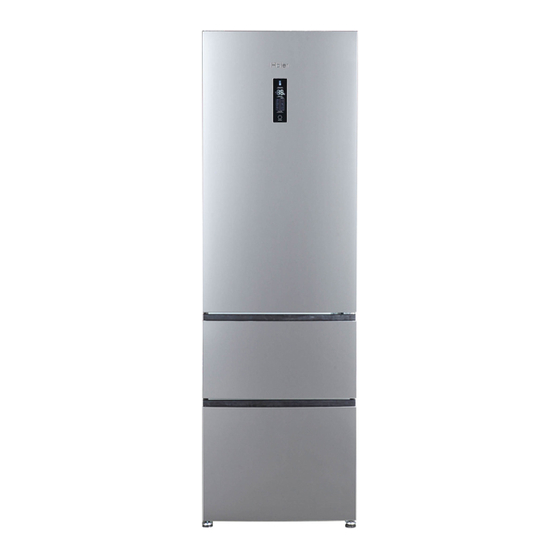
SERVICE MANUAL Issue Rev. Model: 2-2. External views 2-2-1.A2FE635CFJRU 2-2-2.C2FE636CFJRU /C2FE636CSJRU/C2FE636CWJRU... - Page 13 SERVICE MANUAL Issue Rev. Model: 2-2-3.A2FE637CXJRU 2-2-4.C2FE637CXJRU...
-
Page 14: Major Features
SERVICE MANUAL Issue Rev. Model: 2-3. Major features 2-3-1.Features New appearance of three stainless steel doors, fashionable and luxurious, satisfies the demands of the modern high-income families. Fully closed freezing system and drawer storage can avoid food tainting, keep cold and are energy-saving. As warm air can't easily enter into the storage area when opening the door. - Page 15 SERVICE MANUAL Issue Rev. Model: 2-3-2.Explanation of The Models COOLING USER PRODUCT FAMILY TECHNOLOGY INTERFACE CLASS VOLUME = 45-54 lt A1 = 3D Gen 1 F= FULL NO M= Mechanical 9= A++++ FROST = 135-144 lt A2 = 3D Gen 2 S= DIRECT S= Semi 8=A+++...
-
Page 16: Installation, Adjustments And Maintenance
SERVICE MANUAL Issue Rev. Model: Chapter 3 Installation, adjustments and maintenance 3-1. Door (Refrigerator door, Freezer door) 3-1-1.Removing and replacing the right door of refrigerator compartment 3-2. Water pipe A) Unscrew the four screws which secure the front panel located at the top; B) Push the front panel upward to withdraw the front panel;... - Page 17 SERVICE MANUAL Issue Rev. Model: A) Remove the top hinge from the refrigerator door; B) With the aid of pliers, unscrew and remove the screws on the top of the hinge, then loosen and remove the pin on the bottom of the hinge; then re-install the A) transfer the display cable located in the slit above the refrigerator door from left to right, always keeping it inside the slit, and connect it to the electric cable...
- Page 18 SERVICE MANUAL Issue Rev. Model: 3-1-2.Removing and replacing the right door of freezer compartment (For C2FE636CFJRU /C2FE636CSJRU/C2FE636CWJRU/C2FE637CXJRU) Before change Refrigerator After change Middle hinge Screws affixed to the middle hinge Hole plug Middle hinge axis lower hinge Screws affixed to the lower hinge Directions on how to dismantle and install the middle and lower hinges ⑴...
-
Page 19: 3-2.Adjustable Foot
SERV RVICE M MANU ssue Rev. Model: 3-2. Ad justable foot Level the cabinet. Th e refrigerato or should be e placed on a flat and s solid surface e. If the refri igerator is placed on an uneven surface, fla at strong an d fire- resis tant materia... - Page 20 SERV RVICE M MANU ssue Rev. Model: poweri nterruptiono occurs, pleas secall thepo owercompan nytoaskabou utthe interrup ptionduration Donotp putadditiona alfoodintothe erefrigerator duringapo ower interru uptionandtry ytoopen the edoor as fewtim esas possib ble. Ifpriorn noticeofapow werinterrupti ionis given andtheinte rruptiondura ationis over r24 hours,m...
-
Page 21: Disassembly
SERVICE MANUAL Issue Rev. Model: Chapter 4 Disassembly 4-1.A2FE635CFJRU/A2FE637CXJRU Freezer doorassembly 4-1-1. Disassembly of the freezer’s upper door body ① Open upper drawer of the freezer; ② Make the front-ends of the drawer and the tray lean upward a little according to illustration ②;... -
Page 22: Display Screen Assembly
SERVICE MANUAL Issue Rev. Model: off the bottom door body,; ⑤⑥⑦ Display screen assembly 4-2. Press a sucker onto the middle of the display screen gently, and take off the display screen from the door body of the refrigerating chamber, and then take apart the terminal. - Page 23 SERVICE MANUAL Issue Rev. Model: ① Take the air duct of the chiller chamber out of the cover board; ② Unplug the terminal of the ① ② air door and take off the air door. 4-3-4. Disassembly of the air duct of the freezer ①...
-
Page 24: Compressor Assembly
SERVICE MANUAL Issue Rev. Model: Compressor assembly 4-4. Illustration of the compressor chamber components: Material list: Name of material Specific No. Qty. Self-tapping screw 0060112284 Compressor NX1116Y(Include Capacity ) 0060702332 Supporting plate assembly of compressor 0060830615 SCREW 0060600186 Evaporating utensil 0060222122 DAMPING MAT 0060220107... -
Page 25: Disassembly Method Of Heating Wire For Defrosting
SERVICE MANUAL Issue Rev. Model: 4-5. Disassembly of the heating wire for defrosting Take out the 2 plug ① terminals connected with the defrosting cable in the red circles; ② As the red circle shown in illustration ② , gently break ①②③... -
Page 26: Control And Display System
SERVICE MANUAL Issue Rev. Model: Chapter 5 Control and display system 5-1. Control and display panel 5-2. Function adjustment Fridgestorage temperaturesetup Press key A1 repeatedly until indicators B inlluminates; press A2 to set the refrigerator temperature. ,corresponding indicators B and D begin to flash simultaneously. The temperature increases by 1℃... - Page 27 SERVICE MANUAL Issue Rev. Model: Press key A3 repeatedly until indicators E begin to flash; press A4 to confirm the activation of the Super Cooling function. This function can be disabled by repeating the activation procedure manually. This function will be automatically disabled when temperature drops below minimum level.
- Page 28 SERVICE MANUAL Issue Rev. Model: DisplayControl Thedisplayscreen willturnoff automatically 30 seconds after anoperationisfinished.Itwillbelitup by openingthe dooror pressinganykey. (Alarmdoesnotlightupthedisplayscreen) DoorOpeningAlarm Whentherefrigeratordooris open formorethan3minutes, thebuzzerwillsoundbeepsall the time. Thebuzzercanbesilencedbyclosingthedoor or pressing any keys. If the refrigerator door is left open for over 7 minutes, the internal light automatically switches off. Turningoff/on theRefrigerator When the refrigerator is working, if you press key A4 for 5 seconds, the whole refrigerator will be switched off.
-
Page 29: Error Code Display And Sensor Positions
SERVICE MANUAL Issue Rev. Model: 5-3. Error code display and sensor positions When the refrigerator runs abnormally, it can enter into the mode of malfunction check by manually adjusting the display board. Entering method: Open the refrigerator door,after the display board is lighted, press the key of “Temp Zone”, and at the same time press the key of “Temp Set”... - Page 30 SERVICE MANUAL Issue Rev. Model: Notes: when checking the practical temperature of each sensor, distinguish the name of the presently displayed sensor according to the above table. The temperature display area of “-88” displays the integer figures of the practical temperature of the current sensor. One decimal figure of the practical temperature is displayed through 4 functional icons as shown in the following table: Represent Displayed icon...
- Page 31 SERVICE MANUAL Issue Rev. Model: Correspondence table of refrigerator malfunction codes: Position of Item Code Content sensor RT SNR error RT SNR short circuit or open circuit Door body Air duct of R SNR error R SNR short circuit or open circuit refrigerating chamber Air duct of...
- Page 32 SERVICE MANUAL Issue Rev. Model: Graphic display of the sensor location Ambient temperature sensor Fridge storage temperature sensor Chiller temperature sensor Defrosting Freezer storage temperature sensor temperature sensor Name of sensors Distance to the Distance to the right Distance to the top (mm) side (mm) left side (mm)
-
Page 33: Control Principle Of Electronic Component
SERVICE MANUAL Issue Rev. Model: Chapter 6 Control principle of electronic component 6-1. Fan cooling system (1)Air escaper’s open and close is controlled by fridge sensor R SNR. (2)Air escaper is closed firstly and then opened once, then open or close of air escaper is controlled according condition (1). -
Page 34: Electromagnetic Valve
SERVICE MANUAL Issue Rev. Model: than 90 minutes, when the defrosting sensor malfunction (short circuit or open circuit). If defrosting time is more than 90 minutes and the defrosting sensor temperature can’t reach 8ºC, the product will disconnect defrosting heater, and display ED on fridge display area under malfunction mode until in some defrosting cycle the defrost sensor temperature reach 8 ºC. -
Page 35: System Flow Principle
SERVICE MANUAL Issue Rev. Model: Chapter 7 System flow principle 7-1. Refrigeration flow chart The refrigeration system of direct cooling single-system cooler belongs to the category of a single-temperature and single-control refrigerating system with one evaporators and is controlled by a single temperature control. -
Page 36: Refrigeration Flow Scenograph
SERVICE MANUAL Issue Rev. Model: 7-2. Refrigeration flow scenograph... -
Page 37: Air Flow Scenograph
SERVICE MANUAL Issue Rev. Model: 7-3. Air flow scenograph 7-4. Water supply flow scenograph None... -
Page 38: Circuit Diagram
SERVICE MANUAL Issue Rev. Model: Chapter 8 Circuit diagram 8-1. Brief principle diagram A.Power plug B. Refrigerator sensor C. Chiller sensor D. Freezer sensor E .Defrost sensor F.Ambient sensor G.Display panel H. Refrigerator lamp I.Hall IC J.Damper K.Freezer Fan Motor L. -
Page 39: Main Control Pcb Diagram
SERVICE MANUAL Issue Rev. Model: 8-2. Main control PCB diagram... -
Page 40: Quick Check
SERVICE MANUAL Issue Rev. Model: Chapter 9 Quick check 9-1. Self test model Entering method of TEST function: Open the refrigerator door,press the keys of “Func.Set” and “OK” at the same time, press the key of “OK” and press the key of “Func.Set” for 10times at the same time to enter the TEST function mode. -
Page 41: Pcb Checkout
SERVICE MANUAL Issue Rev. Model: 9-2. PCB checkout 9-2-1. PCB diagram... - Page 42 SERVICE MANUAL Issue Rev. Model: 9-2-2. PCB photo 9-2-3. PCB connection technical data Connector Connection Testing part Testing part location Normal data 1.NULL 2.NULL 3.NULL 1.Black Evaporating The inside of the air duct of Working volt motor the freezer 8V-13V 2.Orange 3.
- Page 43 SERVICE MANUAL Issue Rev. Model: 6.Green Display board of the The outside of the door Working volt 5V door body body of the refrigerating 7.Red chamber 8.Brown 9.Blue 10-12 NULL 1.White Environment The door body of the Working volt 0-5V temperature sensor refrigerating chamber 2.White...
-
Page 44: Trouble Shooting
SERVICE MANUAL Issue Rev. Model: Chapter 10 Trouble shooting 10-1.Abnormal phenomena Symptom:food in the fridge storage compartment is frozen Check: 1) Verify that the temperature in the fridge storage compartment is too low and the food is frozen there; 2) Disconnect the connection wires of the damper and the LED lamps. Take out the air door-foam assembly. - Page 45 SERVICE MANUAL Issue Rev. Model: Symptom:neither displaying nor starting when powering on Check: 1) Check if the power supply is connected properly. 2) Remove the main control panel and examine its back side carefully to see if there are solder skips or open soldering; 3) Check if the connector of the freezer door hinge is connected properly.
- Page 46 SERVICE MANUAL Issue Rev. Model: Sincere forever Haier Group Haier Industrial Park, No.1, Haier Road 266101, Qingdao, China http://www.haier.com...
Need help?
Do you have a question about the A2FE635CFJRU and is the answer not in the manual?
Questions and answers