Table of Contents
Advertisement
Quick Links
Advertisement
Table of Contents

Related Manuals for Motorola APX7500 03


Summary of Contents for Motorola APX7500 03
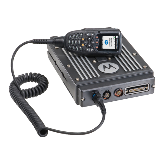
- Page 1 APX7500 03 Mobile User Guide...
-
Page 3: Declaration Of Conformity
DECLARATION OF CONFORMITY Per FCC CFR 47 Part 2 Section 2.1077(a) Responsible Party Name: Motorola, Inc. Address: Motorola, Inc. 1301 E. Algonquin Rd.Schaumburg, IL60196-1078, U.S.A. Phone Number: 1-800-927-2744 Hereby declares that the product: Model Name: APX 7500 conforms to the following regulations: FCC Part 15, subpart B, section 15.107(a), 15.107(d) and section 15.109(a) - Page 4 Note: This equipment has been tested and found to comply with the limits for a Class B digital device, pursuant to part 15 of the FCC Rules. These limits are designed to provide reasonable protection against harmful interference in a residential installation.
-
Page 5: Table Of Contents
Programmable Features ..... 6 Contents Assignable Radio Functions ....6 Assignable Settings/Utility Functions . - Page 6 General Radio Operation ....22 Permanent Monitor ..... . . 30 Selecting a Zone or Channel .
- Page 7 Viewing an Entry in the Scan List ... . 42 To Login as a User ..... . . 51 Editing the Scan List .
- Page 8 Utilities ........64 Push-To-Talk Identification (PTT-ID) ..71 Locking and Unlocking the Keypad .
- Page 9 Enhancing GPS Performance ....80 Emergency Channel ..... . 93 Accessing the Outdoor Location Feature .
- Page 10 viii English...
-
Page 11: Important Safety Information
Important Safety Information Computer Software Copyrights The Motorola products described in this manual may Product Safety and RF Exposure Compliance include copyrighted Motorola computer programs stored in semiconductor memories or other media. Laws in the Before using this product, read the operating... -
Page 12: Documentation Copyrights
However, no responsibility is of Motorola. No part of this manual may be reproduced, assumed for inaccuracies. Furthermore, Motorola reserves the distributed, or transmitted in any form or by any means,... -
Page 13: Getting Started
Notations Used in This Manual Getting Started Throughout the text in this publication, you will notice the use of Take a moment to review the following: WARNING, Caution, and Note. These notations are used to How to Use This User Guide ......emphasize that safety hazards exist, and the care that must be Notations Used in This Manual . -
Page 14: What Your Dealer/System Administrator Can Tell You
What Your Dealer/System Administrator Preparing Your Radio for Use Can Tell You Powering Up the Radio ......page 2 You can consult your dealer or system administrator about the Adjusting the Volume . -
Page 15: Adjusting The Volume
If Error ##/## appears, some non-critical data has Adjusting the Display Brightness been changed. If either of these displays appear, if the display goes blank, or if the unit appears to be locked To change the display brightness, press the programmable DIM up, refer to the “Troubleshooting”section. -
Page 16: Identifying Radio Controls
Radio Control You Will Be Using Identifying Radio Controls The XTS 7500 Digital Mobile Radio has two major components: O3 Control Head Display the radio unit installed in your vehicle and the control head that The control head display indicates your selected mode, or the is used to activate various radio features. -
Page 17: O3 Control Head
O3 Control Head Orange Button The O3 has the Channel and Volume rockers, three programmable menu buttons, navigation buttons, and a 4-line, Power On/Off Button 14-character, fully bitmapped display. Programmable Button Programmable Button Push-To-Talk Button 14-Character Display Volume Rocker Home Button Keypad WAP Button 4-Way Navigation Button... -
Page 18: Programmable Features
Emergency – Depending on the programming, initiates or Programmable Features cancels an emergency alarm or call. Any references in this manual to controls that are Monitor – Monitors a selected channel for all radio traffic until “preprogrammed” mean that a qualified radio technician must function is disabled. -
Page 19: Assignable Settings/Utility Functions
Selective Call (Digital Modes Only) – Provides privacy and to Light/Dim – Changes the display brightness. eliminate the annoyance of having to listen to other Smart Battery – Displays the status of your Smart Battery. conversation. Speaker – Activates external speaker to share your call with Site Lock/Unlock –... -
Page 20: Using The Menu Select Buttons
that radio feature. The radio displays the entry feature when a Menu Entry Feature Page menu entry is selected. PROG Editing You can access the menu entries, as shown in the table below, PSWD Password through the Menu Select buttons. Tx Power Level Menu Entry Feature... -
Page 21: Using The Navigation Buttons
Your radio may be programmed differently from the following Note: Some features do not require you to press the Home button to go to the home display. example, but the display for turning Scan on or off might look like the example below. APP Button (TMS Feature Button) •... -
Page 22: Keypad
Keypad The 3 x 4-key alphanumeric keypad provides an interface to your radio’s features. The keypad functions in a manner similar to a standard telephone keypad when entering numeric digits. When the keypad is used to edit a list, each key can generate different characters of the alphabet. Number of Times Key is Pressed &... -
Page 23: Push-To-Talk (Ptt) Button
Push-To-Talk (PTT) Button Identifying Status Indicators The PTT button on the side of the Your radio indicates its operational status through the following: microphone serves two basic Status Icons ........purposes: Text Messaging Service (TMS) Icons. -
Page 24: Scan
Secure Operation (Secure Radios Only) PPP Link Establishment When solid, radio is transmitting securely. When Indicates that the subscriber is ready to receive data blinking, radio is receiving securely. When off, radio through a data cable. is operating in clear mode. Packet Data Activity Call Received Indicates the subscriber is transmitting and receiving... -
Page 25: Text Messaging Features
Inbox Full Pending for GPS Indicates that GPS system is activated. The Inbox folder is full. icon New Message Icon User receives a new message. Text Messaging Service (TMS) Icons Message Sent The text message is sent successfully. This feature allows you to send and receive text messages. See “Text Messaging Features”... - Page 26 Normal Mode Indicates that the text entry is currently in the normal mode. Uppercase Displayed during text editing mode to indicate that the text entry is currently in uppercase mode. English...
Need help?
Do you have a question about the APX7500 03 and is the answer not in the manual?
Questions and answers