Table of Contents
Advertisement
Quick Links
Saftey Glasses, Tape Measure, Carpenters Level, Framing Square, Hex Head Nut Drivers, Chalk Line,
Recommended Tools:
Elec. Drill w/ Bits (Masonry Drill, Bits & Anchors may be required if securing to stone, concrete, or
any other masonry unit.), Small Screwdriver (to line up Roof Panels)
Before You Begin:
1.) Please read all instructions carefully. Check the Bill of Materials for any missing parts and gather
2.) You may be required to obtain a building permit for this structure from your local building authority.
3.) Note that this Kit is not designed to carry additional loads such as hanging heavy plants, swings,
Windsor Patio Cover
Installation Instructions
necessary tools. To prevent scratching of painted materials, place on a tarp, paper, or protective
material.
This product should only be installed in 10, 20, or 30 psf (pounds per square foot) snow load and
90 mph or less wind speed zone (Custom models can be designed for heavier loads). This product
is listed under ICBO Evaluation Report #2621P. You may have to submit two copies of your plot
plan and also a copy of the evaluation report to your local building authority for a building permit.
Contact your local building department for details and your area's snow & wind loads.
people, or other objects.
Advertisement
Table of Contents

Related Manuals for General Awnings Windsor


Summary of Contents for General Awnings Windsor
- Page 1 Windsor Patio Cover Installation Instructions Saftey Glasses, Tape Measure, Carpenters Level, Framing Square, Hex Head Nut Drivers, Chalk Line, Recommended Tools: Elec. Drill w/ Bits (Masonry Drill, Bits & Anchors may be required if securing to stone, concrete, or any other masonry unit.), Small Screwdriver (to line up Roof Panels) Before You Begin: 1.) Please read all instructions carefully.
-
Page 2: Parts List
Parts List 1. Awning Rail 3. C-Beam 2. Wall Mounting Channel 5. Lower Post Bracket 6. Upper Post Bracket 4. 3" Sq. Post 7. Roof Panel (appr. 2" tall, fits in 3" Post) (appr. 4" tall, fits in 3" Post) 11. - Page 3 STEP 1 -Drill 1/4" holes in the Awning Rail 12" to 16" apart, or wherever stud is found. NOTE: Screws must hit solid wood. -Slide the Awning Rail onto the Wall Mounting Channel before mounting to wall. -Mark a level line approximately 5-1/2" above outswinging door (see Fig. 1-3). -Apply a generous bead of silicone to the back of the Awning Rail.
- Page 4 STEP 2 -Attach Upper Post Brackets to 3" Sq. Posts with 2 - Tek 5 x 1 1/4" Screws per side. -Cut the post to proper height; we recommend front height of the cover should be 1/2" per foot of projection lower than mounting height (see Fig.
- Page 5 STEP 4 -Place a Roof Panel over the C-Beam and match the holes. -Use Hex Head 3/4" Lag Screws to attach Roof Panels to the C-Beam through each hole. -Slide or snap Roof Panels into place. -After second or third Roof Panel is installed, check the front ends and make sure they are flush with each other; keeping the Roof Panels flush in front will align the cover square with the structure.
- Page 6 STEP 6 -Install a Fascia Clip on each Roof Panel as shown (see Fig. 6-1). -Install the Front Fascia on the end with fabricated corner. -Hook the top lip of the Front Fascia into the Fascia Clip slot (see Fig. 6-2). -Let it hang loose.
- Page 7 STEP 7 -Make sure the Styrofoam Bird Plug was not removed from one end of both Projection Fascias. Caulk around the inside face. -Hold the rear end of the Projection Fascia approximately 12" away from the Wall Mounting Channel next to the house. -Slip the front end of the Projection Fascia inside of the Front Fascia fabricated corner.
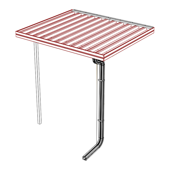
- Page 8 Optional Downspout Assembly -Cut a hole in the desired location in Front Fascia. Recommended in front of a post. -Using 3/4" Tek 2 Screws, attach the downspout fitting over the hole in Front Fascia and caulk. -Attach 2 - 45° elbows to the outlet. -Cut the downspout to desired length.
Need help?
Do you have a question about the Windsor and is the answer not in the manual?
Questions and answers