Table of Contents
Advertisement
Quick Links
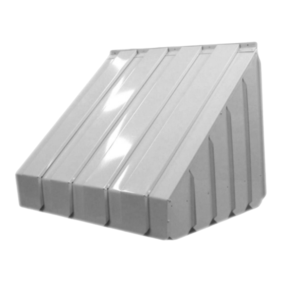
AC1000 PAN & COVER AWNING
ASSEMBLY INSTRUCTIONS
READ ALL INSTRUCTIONS CAREFULLY BEFORE STARTING
THINGS TO CONSIDER BEFORE YOU BEGIN:
*The door or window being covered must clear the understructure of the awning when fully open.
*There should be 78" to 84" distance from the floor or slab to the bottom of the awning when installed over a door so there
is room to walk under it without ducking.
*Smaller awnings can be assembled on the ground and then attached to the building in one piece.
*If columns or posts are necessary for support, they must be attached to a fixed surface or cemented in.
IF INSTALLATION IS ON A BUILDING WITH.....
*Wood or aluminum lap siding-attach mounting rail (flashing) directly under an overlap using 1 ¼" hex head screws at pre-
punched locations. These are punched at 9" centers.
*Aluminum siding with soft backer-it is important to locate the studs before attaching mounting rail (flashing). If the pre-
punched holes do not line up with the studs drill new ones. Be sure to fill all the pre-punched holes with 1 ¼" screws to
avoid any leakage.
*Masonry-follow a mortar line. Drill 1 5/16" deep holes using a 1/4" drill bit at the pre-punched hole locations. Use a fiber
or plastic plug and secure with 1 ¼" screws.
Tools required
Electric drill with 11/64" bit and ¼" bit, tape measure, level, hammer, metal snips, Phillips screw driver, 11/32" and 3/8"
socket or wrench, caulking
Step 1
Run caulking compound along the back of the mounting rail (Part A) that is facing the house, and attach using the correct
application (from above).
SEE PARTS LIST ON PAGE 2.
Pg 1
Advertisement
Table of Contents

Related Manuals for General Awnings AC1000


Summary of Contents for General Awnings AC1000
- Page 1 AC1000 PAN & COVER AWNING ASSEMBLY INSTRUCTIONS READ ALL INSTRUCTIONS CAREFULLY BEFORE STARTING THINGS TO CONSIDER BEFORE YOU BEGIN: *The door or window being covered must clear the understructure of the awning when fully open. *There should be 78” to 84” distance from the floor or slab to the bottom of the awning when installed over a door so there is room to walk under it without ducking.
- Page 2 AC1000 Awning Parts List Part A Part B Part C Mounting Rail Left Side Starter Pan Left Side Louver Section Part D Part E Part F Right Side Starter Pan Right Side Louver Section 8/32" x 3/8" Bolt and Nut...
- Page 3 Step 2 Note: Step 2 and Step 3 must be done on the ground, and then the Awning can be attached to the Mounting Rail that was put on the House in Step 1. Gather the Left Louver Section (Part C), the Right Louver Section (Part F), and the Runner(s) (Part H). Place the Runner(s) (Part H), slots facing toward the front of the Awning, at pre-punched holes located on the Rafter of the two louver sections.
- Page 4 Step4 Attach the Left side Starter Pan/Louver Section you’ve just assembled to the Mounting Rail on House: Use Bolts & Nuts (Part D) in the pre-drilled hole(s) at the top of the Left side Starter Pan (Part B) into the pre-drilled hole(s) on the left end of the Mounting Rail (Part A).
- Page 5 Step 6 Move to the next set of holes in the Mounting Rail (Part A). Attach a Bottom Pan (Part I) to the Mounting Rail (Part A) using Bolts & Nuts (Part D). Bend valances downward just slightly for now. Once all bottom pans are in place and secured to the flashing, bend the front valance sections the rest of the way to match starter pans.
- Page 6 PROCEED TO STEP 8. If your Awning is less than 48” Projection, please In cases where projection is 48” and over and posts are necessary for support. First, install the supplied Rafter Brace (Part M) by attaching it to the house/structure, underneath the Mounting Rail (Part A), using Lag Bolt (Part G). Also attach the Rafter Brace (Part M) to the Runner(s) (Part H) using Self-Tapping Screws (Part L).
- Page 7 Step 8 Top Pans (Part K) are placed between the Bottom Pans (Part I) that are already in place. Push a top pan over the preformed tab on the Mounting Rail (Part A) until it is locked in position. Press the Top Pans (Part K) onto each Runner Clip (Part J).
Need help?
Do you have a question about the AC1000 and is the answer not in the manual?
Questions and answers