Advertisement
A
SSEMBLY
:
I
MPORTANT
READ ALL ASSEMBLY INSTRUCTIONS AND SAFETY PRECAUTIONS BEFO RE USING THIS PRODUCT. REFERENCE ALL
SAFETY GUIDELINES AND WARNING LABELS. RETAIN PRODUCT LITERATURE FOR FUTURE REFERENCE.
S
:
A
FETY
PR
OPERLY WARM UP AND STRETCH BEFORE EXERCISING. IF YOU FEEL PAIN OR DIZZINESS AT ANY TIME WHILE
EXERCISING , STOP IMMEDIATELY AND CONSULT YOUR PHYSICIAN.
I
NSTRUCTIONS
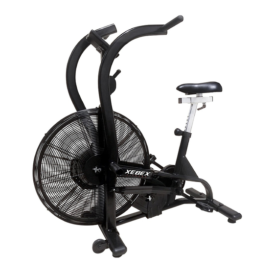
AIR BIKE AB-1
/ O
M
WNERS
ANUAL
Advertisement

Subscribe to Our Youtube Channel
Related Manuals for Xebex Fitness AB-1


Summary of Contents for Xebex Fitness AB-1
- Page 1 AIR BIKE AB-1 SSEMBLY NSTRUCTIONS WNERS ANUAL MPORTANT READ ALL ASSEMBLY INSTRUCTIONS AND SAFETY PRECAUTIONS BEFO RE USING THIS PRODUCT. REFERENCE ALL SAFETY GUIDELINES AND WARNING LABELS. RETAIN PRODUCT LITERATURE FOR FUTURE REFERENCE. FETY OPERLY WARM UP AND STRETCH BEFORE EXERCISING. IF YOU FEEL PAIN OR DIZZINESS AT ANY TIME WHILE...
- Page 2 SSEMBLY NTRO SSEMBLY REPARATION SSEMBLY REPARATION To ensure ease of product assembly, please take time to verify the size and quantities of all required assembly hardware. Use the itemized parts listing and hardware chart for reference. The product assembly process has been documented in easy to follow stages. Please read all assembly instructions carefully.
-
Page 3: Table Of Contents
SSEMBLY ARTS ISTING SSEMBLY ARTS ISTING ITEM# DESCRIPTION Q'TY BASE FRAME ASSEMBLY FRONT STABILIZER ASSEMBLY REAR FRONT STABILIZER ASSEMBLY SENSOR CABLE CONSOLE CONSOLE MAST ADJUSTABLE SEAT SLIDER SEAT POST SEAT SEAT SLIDER ADJUSTABLE KNOB CONNECTING ARM (PREINSTALLED) LEFT PIVOT ARM ASSEMBLY RIGHT PIVOT ARM ASSEMBLY FOOT REST LEFT PEDAL... -
Page 4: Assembly Parts
XPLODED Assembly Parts NOTE NOTE : THE EXPLODED PARTS VIEW IS SHOWN FOR REFERENCE ONLY. SOME ITEMS MAY BE PREASSEMBLED. : THE EXPLODED PARTS VIEW IS SHOWN FOR REFERENCE ONLY. SOME ITEMS MAY BE PREASSEMBLED. PLEASE REFER TO THE INDIVIDUAL ASSEMBLY STAGE INSTRUCTIONS FOR DETAILED PARTS ORIENTATION. PLEASE REFER TO THE INDIVIDUAL ASSEMBLY STAGE INSTRUCTIONS FOR DETAILED PARTS ORIENTATION. -
Page 5: Front Stabilizer Assembly
SSEMBLY NSTRUCTION SSEMBLY TAGE Attach Stabilizers to the Main Base Assembly Hardware Required: Button Head Allen Bolt Qty. 4 Washer Qty. 4 Spring Washer Qty. 4 Assembly Description: A) Assemble the Front Stabilizer Assembly (#2) to the Main Base Assembly (#1) using 2-Button Head Allen Bolt (#22), 2-Spring Washers (#23), and 2-Washers (#24). -
Page 6: Sensor Cable
SSEMBLY NSTRUCTION SSEMBLY STAGE Attach Console Mast & Mount Computer on the Main Base Assembly Hardware Required: Button Head Allen Bolt Qty. 2 Spring Washer Qty. 2 Washer Qty. 2 Assembly Description: A) Carefully route the Sensor Cable (#4) through the Computer Mast (#6) and slide the mast down onto the corresponding mounting area of the Base Frame Assembly. -
Page 7: Adjustable Seat Slider
SSEMBLY NSTRUCTION SSEMBLY TAGE Attach Seat Slider and Seat to Main Base Assembly Assembly Description: A) Insert the Adjustable Seat Slider (#7) into the u-channel of the Seat Support Post (#8). Secure the seat slider assembly in place using the 1-Seat Adjustment Knob (#10). B) Assemble Seat (#9) onto the knurled post of the seat slider. - Page 8 SSEMBLY NSTRUCTION SSEMBLY STAGE Attach Pivot Arms to the Main Base Assembly Hardware Required: Flat Washer Qty. 2 Pivot Bolt M8 Qty. 2 Nylon Nut M8 Qty. 2 Assembly Description: A) Install the Pivot Arms (#16 & #17) by threading the (preinstalled) pivot shaft into the corresponding pivot-boss of the Base Frame Assembly (#1).
-
Page 9: Foot Rest
SSEMBLY NSTRUCTION SSEMBLY STAGE Attach Pedals & Foot Rest to the Main Base Assembly Assembly Hardware Required: (*Assembly hardware may be preinstalled) Pan Head Screw* Qty. 2 Assembly Description: Assembly Note: The right and left pedals are appropriately marked (R) and (L). The threading orientation on the left pedal is reversed from the threading orientation on the right pedal. - Page 10 ROUBLESHOOTING BASIC TROUBLESHOOTING TIPS BASIC TROUBLESHOOTING TIPS PROBLEM DESCRIPTION SUGGESTED SOLUTION NO DISPLAY CHECK BATTERY ORIENTATION: + / - CHECK BATTERY VOLTAGE: (2) AA BATTERIES 1.5 VOLTS EACH CHECK CABLE CONNECTIONS: MAKE SURE CONNECTIONS ARE SECURE AND IN THE CORRECT ORIENTATION. CHECK CABLE ASSEMBLIES FOR DAMAGE: PINCH POINTS &...
- Page 11 REVENTATIVE AINTENANCE QUIPMENT AINTENANCE QUIPMENT AINTENANCE Use a dampened soft-cloth to wipe equipment free of perspiration after each use. Avoid getting excessive moisture on computer or electronic components. Do not use abrasive cleaners or petroleum-based solvents to clean equipment. Do not remove drive train shrouds or attempt any technical service on equipment without consulting an authorized service representative.
- Page 12 XEBEX AIR BIKE Maintenance Information Service Daily Monthly Quarterly Annually Clean/Dry Frame & Console w/ mild soap and cloth Inspect Unit for Noise or loose components Ensure Unit is level-Adjust Stabilizer Feet Tighten Crank & Bell Crank Bolts, Tighten Pedals Tighten Seat Bolts Tighten Handlebars Check and Tighten Linkage Arm Pivot points...
- Page 13 XEBEX AIR BIKE Maintenance Information 4. Linkage Arm Check (Monthly): Tighten the linkage bolts and nuts using a 6mm Allen wrench and 13mm wrench. Tighten these parts snug, but do not over tighten or keep tightening. Note: There will be little play in these linkages after tightening, but this is normal.
-
Page 15: Washer 18*8.5*1.5T
Part List PART DESCRIPTION PART# PART DESCRIPTION PART# FRAME CHAIN FRONT STABILIZER CHAIN REAR STABILIZER SPEED SENSOR BRACKET ZEPHYR COMPUTER WIRE CHAIN TESIONER 4PAIR COMPUTER IDLER HUB COMPUTER POST WHEEL SEAT TRACK RIGHT CHAINGUARD SEAT POST LEFT CHAINGUARD SEAT SPOKE PROTECTOR FIX HANDLEBAR WHEEL CAGE RIGHT KNOB...
Need help?
Do you have a question about the AB-1 and is the answer not in the manual?
Questions and answers