
Related Manuals for ELGO Electric P8721-000-R SERIES


Summary of Contents for ELGO Electric P8721-000-R SERIES
- Page 1 SERIES P8721-000-R Single Axis Position Controller − integrated relay outputs − integrated mains power supply − 3 different speed rates − manual operation mode − single set operation − 200 sets program memory P8721-000-R-E_22-04...
-
Page 2: Table Of Contents
1. SHORT DESCRIPTION 2. FUNCTIONS Two speed operation Three speed operation Setting Datum/Reference Encoder Monitoring Quantity Counter Program counter Fault Monitoring 3. FRONT PANEL Functions of Display Functions of LED’s Function of the Keypad 4. OPERATION MODES Manual mode Single set operation Program Operation (R8/4 = 0) 4.3.1 Selection of a Program Block... - Page 3 8. RELAY CONFIGURATIONS 9. FUNCTIONS OF INPUTS (TERMINALS ST3 AN ST4) 10. FUNCTIONS OF OUTPUTS TERMINALS ST5 & 6 11. CONNECTIONS 11.1 Terminal assignment 12. TECHNICAL SPECIFICATIONS 13. INSTALLATION/WIRING 14. ONLY FOR SERVICE 15. TYPE DESIGNATION 16. LIABILITY EXCLUSION / GUARANTEE...
-
Page 4: Short Description
1. Short Description Features of P8721 2 or 3 speed positioning • absolute and incremental positioning modes • • program memory (200 sets) single set operation • manual operation, slow and fast mode • batch counter with zero-output • • pulse factor datum setting routines •... -
Page 5: Three Speed Operation
Three speed operation NB: R1 > R2 > R3 The value in Register 1 must be larger than R2 Demand position Fast slow creep Stop Offset Creep point Slow point NB: The stop offset is only effective when R8 = 1xxxxx. Setting Datum/Reference Datum can be set in a variety of ways. -
Page 6: Quantity Counter
Quantity Counter Register R18/6 sets the method of counting whether adding or subtracting R18 = xxxxx1 Automatic subtracting R18 = xxxxx2 Automatic adding R18 = xxxxx3 Manual subtracting (external input signal) R18 = xxxxx4 Manual adding (external input signal) R18 = xxxxx5 Automatic add/subtract (Single only) R18 = xxxxx6 Manual add/subtract (Single only) -
Page 7: Fault Monitoring
Fault Monitoring When a fault occurs, it’s number flashes in Actual Value Display Fault number 01 = Encoder 02 = End Limit minimum 03 = End Limit maximum 04 = Actual position < min software limit (R13) Hand Target position < min software limit (R13) Single 05 = Actual position >... -
Page 8: Front Panel
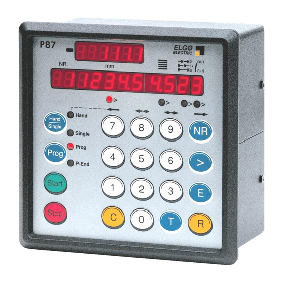
3. Front panel absolute/in sign symbol cremental demand actual selection position position Quantity TYP P8721 ELGO ELECTRIC line adress Helping function > > > > LED 1-4 Hand Hand Single Address number selector Select single / manual Single Prog Select programme Prog Cursor operation... -
Page 9: Function Of The Keypad
ELGO TYP P8721 ELECTRIC > > > > Hand Hand Single Single Prog Prog P-End Start Stop Function of the Keypad Hand/Single 1. Alternate pressing will select “Single”. A Demand position can be entered. Using Cursor > Button enables quantity to also be set. 2. - Page 10 ELGO TYP P8721 ELECTRIC > > > > Hand Hand Single Single Prog Prog P-End Start Stop > The Cursor Button selects the Target windows sequentially. > On completion of a line, the next press of “ ” will select the next Address line. LEDs 1 –...
-
Page 11: Operation Modes
4. Operation modes Switch on conditions are programmable in register R33: R33 = xxxxx 0 same conditions as at time of switch off R33 = xxxxx 1 Single mode R33 = xxxxx 2 Program mode R33 = xxxxx 3 Hand mode The Actual position is memorised. -
Page 12: Program Operation (R8/4 = 0)
Program Operation (R8/4 = 0) 4.3.1 Selection of a Program Block The P8721 has a Program memory of 200 Address lines. These can be divided into several Blocks of equal quantity of lines (see Register R41). Each Block can store a different Program, which can be selected for operation, at will. -
Page 13: Operation In Table Mode
Table mode (R8/4 =1) If R8/4 is set to 1, then the controller operates in 99 selectable address Table mode. Programming is exactly the same as in 4.2.2. 4.4.1 Operation in Table mode An address line of the stored program can be called up and positioning effected to that setting. Press Prog Selects Program mode Press T... -
Page 14: Setting And Changing Register Values
Setting and Changing Register Values Example: The Slowdown Point of 20.0 mm needs to be entered. Assuming that Registers have been unlocked as above :- Press R The Nr Window flashes. Press 1 1 (flashing) is displayed in Nr Window ie Register 01. Press >... -
Page 15: Parameter Table
6. Parameter table Register Function Adjustment-Range Default Customer Slow speed distance (forward) 0.1 mm 200* Creep speed distance (forward) 0.1 mm 100* Correction stop (forward) 0.1 mm Spindle compensation 0.1 mm Retract distance 0.1 mm Tool Width /Tool offset 0.1 mm Datum/reference value 0.1 m 1000... -
Page 16: Description Of Registers
7. Description of Registers Slow speed distance forward/reverse or forward only ( see R28/2). Distance at which the controller switches from high speed to slow speed. The output high speed will be switched off. Creep speed distance forward/reverse or forward only ( see R28/2). Distance to demand position at which the controller switches from slow to creep speed Stop offset distance forward/reverse or forward only ( see R28/2) The overrun distance can be programmed to compensate for distance from the switch-off point of the motor to... - Page 17 System Register 1 This Register sets the basic operating functions of the unit. Target window Spindle compensation 0 = no spindle compensation 1 = negative spindle compensation 2 = positive spindle compensation 3 = negative spindle compensation in range of R24 4 = positive spindle compensation in range of R24 Output Relay Configuration 0 = 3 speed operation Creep ,slow, fast...
- Page 18 Time position reached At the end of each move, the controller gives an output, to signal “in position”. The length of this pulse is set in R9. Setting 0.0 gives a maintained output. This output St5/1-2 is active when Actual position = Demand position +/- Tolerance window R12 Backlash dwell time When the machine stops at the end of the overrun, it is usually desirable to have a short delay.
- Page 19 Software Limit / End Limits Selection Software limits (R13 & R14) are active in accordance with the setting of R15/6 R13/R14 Min/Max software limits Fault Message Target < Limit R13 Target > Limit R14 xxxxx0 Both software limits active xxxxx1 Min software limit (R13) inhibited xxxxx2 Max software limit (R14) inhibited xxxxx3 Both software limits (R13&R14) inhibited External limit switches can be connected to the St4/3 (backwards) and at St4/4 (forwards)
- Page 20 System Register 2 This Register also sets the functions of the controller. Target window batch counter 0 = no batch counter 1 = automatic subtracting 2 = automatic adding 3 = manual subtracting (external input St3/7) 4 = manual adding (external input St3/7) 5 = automatic add/sub (in Single only) 6 = manual add/sub for (in Single only) 7 = automatic subtracting, STOP when “zero”...
- Page 21 Encoder monitoring If after positioning is initiated, no Encoder pulses are sensed after a time set in R19, positioning will be aborted and Fault 01 will be displayed. Setting R19 to 0.0, disables Encoder pulse monitoring. Decimal Point The decimal point is placed in a fixed position and is optical only. It does not change the resolution of the system. The position is dependent on setting of Register R97.
- Page 22 System Register 3 This Register also sets the functions of the controller. Target window Display windows in single mode* 0 = All windows in use 1 = Target alone 2 = Target + batch counter 3 = Target + batch counter + Abs/Incr Front sided START/STOP button interlock 0 = both enabled 1 = STOP disabled...
- Page 23 Number of Lines in each Program Block Enter the number of lines required per Program Block (1 – 99). The number of Blocks will be calculated automatically. Example : Total number of Lines = 200 Number of Lines required per Block = 25 (enter 25 into R41). Therefore the number of program blocks = 8 An entry of Lines over 99 will result in an error message “08”...
- Page 24 System Register 4 This Register sets further basic functions of the controller. Target window Incremental error comp 0 = not active 1 = active External start input 0 = rising edge triggered 1 = falling edge triggered Double start at program-end 0 = without 1 = with Address line stepping...
-
Page 25: Relay Configurations
8. Relay Configurations These depend on setting of Register R8/5 Value 0 3 speed operation (Elgo standard default) 3 speeds selected by relays 2,3, & 4 Relay 5 sets direction reverse ST5 / Pin 3… 10, X = Pin’s closed RELAY outputs 3 - 4 5 - 6... - Page 26 Value = 3 2 speed operation Independent outputs for direction and speed ST5 / Pin 3… 10, X = Pin’s closed RELAY outputs 3 - 4 5 - 6 7 - 8 9 - 10 Creep forwards Slow forwards Fast forwards Creep reverse Slow reverse Fast reverse...
-
Page 27: Functions Of Inputs (Terminals St3 An St4)
9. Functions of Inputs (Terminals ST3 an ST4) St3/1 Terminal for pulling down signals to OV (PNP-Standard Version) (In optional NPN-Version this potential is for pulling up to + 24 V, Factory fitted only) St3/2 External start input The start is edge triggered. Rising or falling edge can be selected in R88/5 St3/3 External stop input Input open Stop active (no positioning possible) - Page 28 St4/1 Terminal for pulling down signals to OV (PNP-Standard Version) (In optional NPN-Version this potential is for pulling up to + 24 V, Factory fitted only) St4/2 System Reset Activating this input will hold the controller in a reset condition, i.e. all outputs & displays are switched off and all other inputs are ignored (For test purpose only).
-
Page 29: Functions Of Outputs Terminals St5 & 6
10. Functions of Outputs Terminals ST5 & 6 St5 pin 1-2 Position reached / in Position The signal is a pulse of time set in R9. When R9 is set to zero, the output is latched till next start is given. The output is set when: Actual value = Demand value +/-Tolerance window R12 Input of R9 = 0... -
Page 30: Connections
11. Connections ST 5 Relays 1-5 ST 4 Input Function PIN Function 1 - 2 Pos. reached/in Pos R1 0 V (PNP) or 24 VDC (Option-NPN) 3 – 4 Creep System Reset 5 – 6 Slow End switch negative 7 - 8 Fast End switch positive 9 –10 Reverse... -
Page 31: Terminal Assignment
11.1 Terminal assignment ST 9 Power Fuse 400mA supply ST 7 RS232 (Option) ST 5 ST 6 Output Output ST 8 (Option) ST 2 Encoder ST 3 ST 4 Input Input 12. Technical specifications Power supply 24 VDC (index 024) (must be indicated) 115 VAC 50/60 Hz (index 115) 230 VAC 50/60 Hz (index 230) -
Page 32: Installation/Wiring
Attention! To ensure a perfect function of the controller P8721 the following installation guide-lines must be strictly observed and followed. Otherwise the guarantee expires and ELGO Electric GmbH takes no liability and guarantee for malfunctions or damages caused e.g. by incorrect installed wires or other external sources of error or interference, which are exactly explained below. -
Page 33: Only For Service
14. Only for Service R99 Service Register When R99 is selected, the following functions can be called up:- Security Register R98 must be opened and service Register R90 set. 000001 Button 0,1and 4 active 000002 All buttons active Notice: Select R90 before R99! Button 0 = Input test ST3 Button 1 =... -
Page 34: Type Designation
15. Type designation P 87 2 1 - 000 - 230 - 0 - R - XXXXXX P = Position Controller Series P8721 with Program memory Program Memory Number of Axes Construction 000 = standard 001 = 1 special version etc. -
Page 35: Liability Exclusion / Guarantee
The guarantee period is two calendar years (EC-Directive) from the date of delivery and includes the delivered unit with all components. ELGO Electric GmbH will at its option replace or repair without charge defects at the unit or the included parts, verifiable caused by faulty manufacturing and/or material in spite of proper handling and compliance to the instruction manual.
Need help?
Do you have a question about the P8721-000-R SERIES and is the answer not in the manual?
Questions and answers