Table of Contents
Advertisement
Advertisement
Table of Contents

Related Manuals for ELGO Electric SERIES P8721-000-P


Summary of Contents for ELGO Electric SERIES P8721-000-P
- Page 1 SERIES P8721-000-P Single Axis Position Controller − PID-analog output (+/- 10 V) and 2 or 3 switched speed positioning − 200 address line program memory − manual operation − single set operation − auxiliary functions P8721-000-P-E_25-04.doc Doku Art. Nr. 799000143...
-
Page 2: Table Of Contents
1. SHORT DESCRIPTION 2. FUNCTIONS 2.1 Two speed operation (switched) 2.2 Three speed operation (switched) 2.3 Option PID-analog +/- 10 V output (regulated) 2.4 Setting Datum/Reference 2.4.1 Operation of Go to Datum 2.6 Encoder monitoring 2.7 Batch counter 2.8 Program counter 2.8.1 Auxiliary Functions 2.9 Fault monitoring 3. -
Page 3: R28 - System Register
5.3 Locking of Registers 6. REGISTER LIST 7. DESCRIPTION OF REGISTERS R8 - System Register 1 7.1 Backlash positioning 7.2 Output configurations R18 - System Register 2 R24 – Forced loop range window R25 - Fixed Position (PID only) R28 - System Register 3 Parameters for Analog (PID) Control (R50-R58): R88 - System Register 4 R99 - ONLY FOR SERVICE... -
Page 4: Short Description
1. Short Description Whilst the P8721-000-P with option Analog-output is specifically designed to provide closed loop (proportional, integral, differential) analog control of 4 quadrant drives, it also serves the purpose of operating as a 2 or 3 speed controller, as the P8721-000-R. When used as a closed loop controller, it is essential that: A 4 quadrant drive –... -
Page 5: Functions
2. Functions The P8721-000-P can be configured for switched speed or regulated PID-analog output. 2.1 Two speed operation (switched) NB: R1 = R2 > R3 The value in Register 1 must be the same value as R2 Fast (and slow) target position creep stop offset... -
Page 6: Option Pid-Analog +/- 10 V Output (Regulated)
2.3 Option PID-analog +/- 10 V output (regulated) (see pages 32/33 for full description) The setting is effected using Registers R50 to R66 2.4 Setting Datum/Reference Datum can be set in a variety of ways. The method is selected in Register R8/3 R8 = xx0xxx Datum to R7 Closing input St 3 / 4 transfers the value set in R7 into Actual Value Display... -
Page 7: Encoder Monitoring
2.6 Encoder monitoring If after positioning is activated, no Encoder pulses are received after a time set in R19 (0.1 to 9.9 sec), positioning will be aborted and fault 01 will be displayed. Setting R19 to 0.0 sec, disables this feature. -
Page 8: Auxiliary Functions
2.8.1 Auxiliary Functions When operating in program mode, an auxiliary function can be selected on each address line. The setting is 0 – 9. The outputs appear on St5/18 to 21, binary coded. The output is set when the appropriate address line is selected and start given. It will remain active on until the new line is selected and start activated. -
Page 9: Front Panel
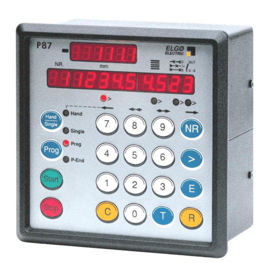
3. Front Panel absolute/in sign symbol cremental demand actual selection position position Quantity Auxiliary function TYP P8721 ELGO ELECTRIC Adress > > > > LED 1-4 Hand Hand Single Address number selector Select single / manual Single Prog Select programme Prog Cursor operation... -
Page 10: Function Of The Keypad
TYP P8721 ELGO ELECTRIC > > > > Hand Hand Single Single Prog Prog P-End Start Stop 3.3 Function of the Keypad Hand/Single 1. Alternate pressing will select “Single”. A Demand position can be entered. Using Cursor > Button enables quantity to also be set. 2. - Page 11 TYP P8721 ELGO ELECTRIC > > > > Hand Hand Single Single Prog Prog P-End Start Stop > The Cursor Button selects the Target windows sequentially. > On completion of a line, the next press of “ ” will select the next Address line. LEDs 1 –...
-
Page 12: Controller In Operation
4. Controller in Operation Switch on conditions: On switch on, the controller assumes the same conditions as at time of switch off. The Actual position is memorised. In “Hand” and “Prog”, the Target windows are set to zero. In “Single” the Demand value is made to equal Actual value. When automatic datum routine feature is selected,R8/3 = 2 or 3 the controller will not operate, until the datum routine has been carried out. -
Page 13: Enter A Program
4.2.2 Enter a program The required Program Block is selected in accordance with section 4.2.1. Press Prog Selects Program mode Press Nr “01” appears in Nr Window. LED illuminates under Target window. Press C Clears existing value. Use Keys 0 – 9 To enter new dimension. -
Page 14: Manual Operation
4.4 Manual operation Press T Resets target windows to zero Use the Button “Hand/Single” to select “Hand”. LED “Hand” illuminates. Buttons 7/8/9/NR can be used to move the axis forward and backwards at high and low speeds (whilst the button is depressed). The remaining buttons are inhibited in manual mode. The Buttons have the following functions : Button 7 Slow Reverse... -
Page 15: Setting And Changing Register Values
5.2 Setting and Changing Register Values Example: The Slowdown Point of 20.0 mm needs to be entered. Assuming that Registers have been unlocked as above : Press R The Nr Window flashes. Press C Clears display to zero. Press 1 1 (flashing) is displayed in Nr Window i.e. -
Page 16: Register List
6. Register List (Registers signed as * can be changed without security code) Function Range Default setting Customers setting Slow speed distance 0.1 mm Creep speed distance 0.1 mm Stop offset 0.1 mm Backlash compensation 0.1 mm Retract distance 0.1 mm R 6 * Tool Width 0.1 mm... -
Page 17: Description Of Registers
7. Description of Registers R1 - Slow speed distance Distance to demand position at which the controller switches from high speed to slow speed. The output high speed will be switched off. R2 - Creep speed distance Distance to demand position at which the controller switches from slow to creep speed R3 - Stop offset distance The over run distance can be programmed to compensate for distance from the switch-off point of the motor to standstill. -
Page 18: R8 - System Register 1
R8 - System Register 1 This Register sets the basic operating functions of the unit. Target window Spindle compensation 0 = no spindle compensation 1 = negative spindle compensation 2 = positive spindle compensation 3 = negative spindle compensation with forced loop (R24) 4 = positive spindle compensation with forced loop (R24) 5 = negative spindle compensation with backlash 6 = positive spindle compensation with backlash... -
Page 19: Backlash Positioning
7.1 Backlash positioning Adjustable in register R8/6 R8 = XXXXX5 Backlash with negative spindle compensation R8 = XXXXX6 Backlash with positive spindle compensation If the actual value after positioning is inside the range of the backlash window, with next START a new positioning (if necessary with forced loop) will be proceeded to the old target position. -
Page 20: Output Configurations
7.2 Output configurations These depend on setting of Register R8/5 Value 0 3 speed operation (Elgo standard default) 3 speeds selected by relays 1,2 & 3 output 4 sets direction reverse OUTPUT ST5/ Creep forwards Slow forwards Fast forwards Creep reverse Slow reverse Fast reverse R1 = Run, R2 = Slow &... - Page 21 Value 3 2 speed operation Independent outputs for direction and speed OUTPUT ST5/ Creep forwards Slow forwards Fast forwards Creep reverse Slow reverse Fast reverse Value 4 3 speed operation Forwards – 3 Outputs set speeds Reverse – always fast Output 4 = reverse OUTPUT ST5/ Creep forwards...
- Page 22 R9 - Time position reached At the end of each move, the controller gives an output, to signal “in position”. The length of this pulse is set in R9. Setting 0.0 gives a maintained output. This output St5/14 is active when Actual position = Demand position +/- Tolerance window R12 R10 - Backlash dwell time When the machine stops at the end of the over run, it is usually desirable to have a short delay.
- Page 23 R13/R14 - Min/Max software limits Fault Message Target < Limit R13 Target > Limit R14 Single set operation Immediately after a start signal, the controller checks the software limits. If the Demand position is greater or smaller than the corresponding limit, the controller will stop and show the error message on the display.
-
Page 24: R18 - System Register 2
R18 - System Register 2 This Register also sets the functions of the controller. Target window batch counter 0 = no batch counter 1 = automatic subtracting 2 = automatic adding 3 = manual subtracting (external input St3/7) 4 = manual adding (external input St3/7) 5 = automatic add/sub (in Single only) 6 = manual add/sub for (in Single only) 7 = automatic subtracting, STOP when “zero”... -
Page 25: R24 - Forced Loop Range Window
R19 - Encoder monitoring If after positioning is initiated, no Encoder pulses are sensed after a time set in R19, positioning will be aborted and Fault 01 will be displayed. Setting R19 to 0.0, disables Encoder pulse monitoring. R20 - Decimal Point The decimal point is placed in a fixed position and is optical only. -
Page 26: R28 - System Register 3
R28 - System Register 3 This Register also sets the functions of the controller. Target window Display windows in single mode* 0 = All windows in use 1 = Target alone 2 = Target + batch counter 3 = Target + batch counter + Abs/Incr Front sided START/STOP button interlock 0 = both enabled 1 = STOP disabled... - Page 27 R29 - Time Delay for Drive inhibit (Positioning) On activating start, output St5/15 is activated. On arriving in position, after a time delay of R29 this output deactivates. R30 - Program End On reaching the last line of the program, & completing the move and quantity batch, the program end output ST5/17 will pulse for the time set in this register.
-
Page 28: Parameters For Analog (Pid) Control (R50-R58)
Parameters for Analog (PID) Control (R50-R58): R50 - Speed (input in rpm, referred to Encoder) The maximum speed is set in this Register, in rpm. The speed is monitored by the Encoder speed (1 – 10000 rpm). Should there be gearing between motor and Encoder, this must be considered in the calculation to set R50. - Page 29 R58 - Stop characteristics This Register sets the stop characteristics of the controller in the different stop conditions. Target window Stop characteristics of front-panel stop-key Stop characteristics of external stop-input Stop characteristics of limit-switch and software limit Stop characteristics in Hand mode fast Stop characteristics in Hand mode slow Stop characteristics at encoder error Value 0 = Stop smoothly (Ramp of R51)
-
Page 30: R88 - System Register 4
R88 - System Register 4 This Register sets further basic functions of the controller. Target window Incremental error comp 0 = not active 1 = active External start input 0 = rising edge triggered 1 = falling edge triggered Double start at program-end 0 = without 1 = with Address line stepping... -
Page 31: R99 - Only For Service
R99 - Only for Service R99 Service Register When R99 is selected, the following functions can be called up:- Security Register R98 must be opened and service Register R90 set. R90 = 000001 Button 4 active R90 = 000002 All buttons active NB: Select R90 before R99 Button 0... -
Page 32: Positioning With Analog Pid Output
8. Positioning with analog PID output Analog range +/- 10 V By using registers R50... R66 the analog output will be adjusted Speed rpm I – Limit or demanded rpm’ s Time 8.1. Offset adjustment of closed loop analog system When the position controller is connected to the motor drive, it is possible to come “into position”... -
Page 33: Setting Of Analog Parameters
8.2 Setting of Analog Parameters Initial settings : Enter Encoder Resolution in R57 (max 10000 ppr) Set Edge Multiplier in R56 Set the desired speed in R50 (for program and single) and R60-63 (for Hand) – max 10000 rpm. The product of Encoder Resolution and rpm should not exceed the maximum input frequency of the controller. -
Page 34: Functions Of The Inputs (Connector St3)
9. Functions of the inputs (Connector St3) St3/3+7 End limits External limit switches can be connected Input logic is NPN i.e. input open = end limit activated St3/3 minimum end limit St3/7 maximum end limit Fault monitoring : End limit minimum active = 02 End limit maximum active = 03 Notice: If these are not connected to limit switches they need to be connected Normally closed (i.e. -
Page 35: Functions Of The Outputs
10. Functions of the Outputs St5/1-4 Run Signals The functions are selectable. See page 20/21 St5/5 Single Operation This output is set when Single is selected St5/6 Hand Operation This output is set when Hand is selected St5/7 Going to Datum If this feature is selected in R8/3, then on activating start, this output is set. -
Page 36: Connections
11. Connections St5 Output Signals (Push Pull) St3 Input Signals Creep These run signals are confi- Please note: PNP (standard) inputs must be connected to + 24 V Slow gurable in a number of ways NPN (optional) inputs must be connected to 0 V (GND) Fast see pages 19/20 (these sig- Reverse... -
Page 37: Connector Assignment (Rear)
11.1 Connector assignment (Rear) St 9 Encoder Input 115VAC Input signals 230VAC Output signals Serial interface Analog signals Power supply 12. Technical specifications Power supply 24 VDC (index 024) (must be indicated) 115 VAC 50/60 Hz (index 115) 230 VAC 50/60 Hz (index 230) Power consumption 14 VA Consumption... -
Page 38: Installation/Wiring
Attention! To ensure a perfect function of the controller P8721 the following installation guide-lines must be strictly observed and followed. Otherwise the guarantee expires and ELGO Electric GmbH takes no liability and guarantee for malfunctions or damages caused e.g. by incorrect installed wires or other external sources of error or interference, which are exactly explained below. -
Page 39: Type Designation
14. Type designation P 87 2 1 - 000 - 230 - 0 - P - XXXXXX P = Position controller Series P8721 with Program memory Program Memory Number of Axes Construction 000 = standard 001 = 1 special version etc. -
Page 40: Liability Exclusion / Guarantee
The guarantee period is one calendar year from the date of delivery and includes the delivered unit with all components. ELGO Electric GmbH will at its option replace or repair without charge defects at the unit or the included parts, verifiable caused by faulty manufacturing and/or material in spite of proper handling and compliance to the instruction manual.
Need help?
Do you have a question about the SERIES P8721-000-P and is the answer not in the manual?
Questions and answers