Table of Contents
Advertisement
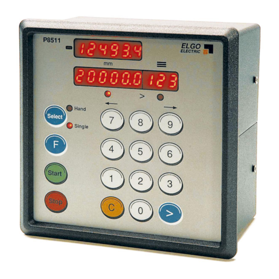
SERIES P8511-000-P
Single Axis Position Controller
for regulated (PID) positioning
P8511-000-P-E_25-04.doc
PID – regulated analogue positioning with +/- 10 VDC
•
Integrated power pack (115/230 VAC)
•
Single set operation
•
Up to three different speeds
•
Manual (inching) operation
•
Extensive functions and parameters
•
Doku Art. Nr. 799000133
Advertisement
Table of Contents

Related Manuals for ELGO Electric P8511 Series


Summary of Contents for ELGO Electric P8511 Series
- Page 1 SERIES P8511-000-P Single Axis Position Controller for regulated (PID) positioning PID – regulated analogue positioning with +/- 10 VDC • Integrated power pack (115/230 VAC) • Single set operation • Up to three different speeds • Manual (inching) operation • Extensive functions and parameters •...
-
Page 2: Table Of Contents
1. SHORT DESCRIPTION 2. FUNCTIONS Two speed operation Three speed operation PID - Analogue +/- 10 V regulation (optional) Setting Datum Encoder Monitoring Quantity Counter Fault Monitoring 3. FRONT PANEL Functions of Display 3.2. Function of the Keypad 4. CONTROLLER IN OPERATION Position to new value Manual operation (Hand) 5. -
Page 3: Short Description
1. Short Description Whilst the P8511-000-P with option Analogue-output is specifically designed to provide closed loop (Proportional, Integral, Differential) analogue control of 4 quadrant drives, it also serves the purpose of operating as a 2 or 3 speed controller, as the P8511-000-R. When used as a closed loop controller, it is essential that: - 1. -
Page 4: Functions
2. Functions Two speed operation NB: R1 = R2 > R3 The value in Register 1 must be the same value as Register 2 F ast (and slow) D emand position creep S top Offset Creep point Three speed operation NB: R1 >... -
Page 5: Setting Datum
Setting Datum Datum can be set in a variety of ways. The method is selected in Register R8/3 R8 = xx0xxx Datum to R7 Closing input St 3 / 4 transfers the value set in R7 into Actual Value Display R8 = xx1xxx Setting to Preset Closing input St 3 / 4 transfers the Target display... -
Page 6: Quantity Counter
Quantity Counter Register R18/6 sets the method of counting whether adding or subtracting R18 = xxxxx1 Automatic subtracting R18 = xxxxx2 Automatic adding R18 = xxxxx3 Manual subtracting (external input signal) R18 = xxxxx4 Manual adding (external input signal) R18 = xxxxx5 Automatic add/subtract (Single only) R18 = xxxxx6 Manual add/subtract (Single only) -
Page 7: Front Panel
3. Front Panel Demand Quantity Minus Symbol Position Actual Position ELGO ELECTRIC P8511 > LED 1-2 Hand Select single position Select or Hand operation Single Function button Start Positioning Start > Stop Positioning Stop Clear Button Cursor Button Functions of Display Actual Position Shows the Actual Position of the axis Target Position Here you can enter the required position (or Register value) -
Page 8: Controller In Operation
4. Controller in Operation Switch on conditions is programmable in register R33: R33 = xxxxx0 same conditions as at time of switch off R33 = xxxxx1 Single mode R33 = xxxxx3 Hand mode The Actual position is memorised. In “Hand” the Target window line is switched off. In “Single”... -
Page 9: Setting Of Registers
5. Setting of Registers Register Input Press F for 2 sec The digits in Actual value display flash. 98 is displayed when Registers are protected by security code. To unlock Registers :- Press > Select Target window Enter 250565 The security code Thereafter, the required Register is displayed. -
Page 10: Register List
6. Register List Register Function Resolution Suggested Custome initial setting Slow speed distance 0.1 mm Creep speed distance 0.1 mm Stop offset 0.1 mm Backlash compensation 0.1 mm Retract distance 0.1 mm 06 * Tool Width 0.1 mm Datum value 0.1 m 1000 System Register 1... - Page 11 Speed forward hand fast 1000 Speed forward hand slow Direction of manual buttons Speed to fixed position Acceleration for fixed position revs/sec2 Speed datum sequence phase 1 Speed datum sequence phase 2 Speed datum sequence with 0,1,2 relays phase 1 System Register 4 See para 7.42 000000...
-
Page 12: Description Of Registers
7. Description of Registers Slow speed distance forward/reverse or forward only (see R28/2) Distance at which the controller switches from high speed to slow speed. The output high speed will be switched off. Creep speed distance forward/reverse or forward only (see R28/2) Distance to demand position at which the controller switches from slow to creep speed Stop offset distance forward/reverse or forward only (see R28/2) The overrun distance can be programmed to compensate for distance from the switch-off... - Page 13 Datum The Datum value is stored in this Register. The value is used in different ways, in accordance with setting of P8/3. Input St3/8 initiates loading. This Register can be accessed without Security Code. System Register 1 This Register sets the basic operating functions of the unit. Backlash 0 = no backlash compensation 1 = negative backlash comp...
- Page 14 Output Configurations These depend on setting of Register R8/5 Value 0 3 speed operation (Elgo standard default) 3 speeds selected by relays 1,2 & 3 output 4 sets direction reverse OUTPUT ST5/ Creep forwards Slow forwards Fast forwards Creep reverse Slow reverse Fast reverse R1 = Run, R2 = Slow &...
- Page 15 Value 3 2 speed operation Independent outputs for direction and speed OUTPUT ST5/ Creep forwards Slow forwards Fast forwards Creep reverse Slow reverse Fast reverse Value 4 3 speed operation Forwards – 3 Outputs set speeds Reverse – always fast Output 4 = reverse OUTPUT ST5/ Creep forwards...
- Page 16 Time position reached During each move the controller gives an output to signal “positioning”. When 'in position' the output is deactivated for the length of this pulse set in R9. Setting 0.0 gives a maintained output. This output St5/14 is inactive when Actual position = Target position +/- Tolerance window R12 Backlash dwell time When the machine stops at the end of the overrun, it is usually desirable to have a short...
- Page 17 running into the ends of the machine. The end limit values are modified by backlash value as set in R4, if R8/6 is selected. Software Limit / End Limits Selection Software limits (R13 & R14) are active in accordance with the setting of R15/6 xxxxx0 Both software limits active xxxxx1...
- Page 18 R18 System Register 2 This Register also sets the functions of the controller. Demand Window Quantity Counter 0 = no quantity counter 1 = automatic subtracting 2 = automatic adding 3 = manual subtracting (external input St3/7) 4 = manual adding (external input St3/7) 5 = automatic add/sub (in Single only) 6 = manual add/sub for (in Single only) 7 = automatic subtracting, STOP when “zero”...
- Page 19 Encoder monitoring If after positioning is initiated, no Encoder pulses are sensed after a time set in R19, positioning will be aborted and Fault 01 will be displayed. Setting R19 to 0.0, disables Encoder pulse monitoring. Decimal Point The decimal point is placed in a fixed position and is optional only. It does not change the resolution of the system.
- Page 20 System Register 3 This Register also sets the functions of the controller. Target Window Display windows in single mode 1 = Target Alone 2 = All Windows in use START/STOP button inhibit 0 = both activated 1 = STOP disabled 2 = START disabled 3 = both disabled START inhibit in the tolerance window...
- Page 21 Parameters for Analogue (PID) Control (R50-R58) Speed (input in rpm, referred to Encoder) The maximum speed is set in this Register, in rpm. The speed is monitored by the Encoder speed (1 – 10000 rpm). Should there be gearing between motor and Encoder, this must be considered in the calculation to set R50.
- Page 22 Encoder Edge Multiplication 1 = x 1 2 = x 2 4 = x 4 Entry of any other value will automatically select 1 Encoder Resolution (max 10000 pulses/revolution) The Encoder pulses per revolution are entered in this Register. This enables the calculation of speed to be effected.
- Page 23 Speed to “Fixed Position” (in rpm) The Axis will move to the Fixed Position at this speed, irrespective of other settings. Acceleration (deceleration) for move to Fixed Position (in revs/sec2) This is set irrespective of other values. Speed of going to Datum – First phase (in rpm) Speed of going to Datum –...
- Page 24 Inch/mm conversion mode The setting in this register activates the in inch mode, the free factor and the resolution in the inch mode can be selected. R97/6 =00000x 0 = mm operation 1 = inch operation. Resolution 1/100 2 = inch operation. Resolution 1/1000 3 = factor operation.
- Page 25 Offset Adjustment of Closed loop Analogue system When the position controller is connected to the motor drive, it is possible to come “into position” with an error, due to an analogue offset voltage. This error can be compensated for by adjusting the offset potentiometer of the drive (analogue drives).
-
Page 26: Setting Of Analogue Parameters
Setting of Analogue Parameters Initial settings :- 1. Enter Encoder Resolution in R57 (max 10000 ppr) 2. Set Edge Multiplier in R56 3. Set the desired speed in R50 (for programme and single) and R60-63 (for Hand) – max 10000 rpm. The product of Encoder Resolution and rpm should not exceed the maximum input frequency of the controller. -
Page 27: Functions Of The Inputs (Connector St3)
10. Functions of the inputs (Connector St3) St3/1 Reset St3/3 & 7 End Limits External limit switches can be connected Input logic is NPN i.e. input open = end limit activated St3/3 -ve end limit St3/7 +ve end limit Fault monitoring : End limit –ve active = 02 End limit +ve active = 03 N.B If these are not connected to limit switches they need to be connected... -
Page 28: Functions Of The Outputs
11. Functions of the Outputs St5/1-4 Run Signals The functions are selectable. See page 20/21 St5/5 Single Operation This output is set when Single is selected St5/6 Hand Operation This output is set when Hand is selected St5/7 Going to Datum If this feature is selected in R8/3, then on activating start, this output is set. -
Page 29: Connections
12. Connections Output Signals (Push Pull) Creep These run signals are confi- Slow gurable in a number of ways Fast see page 20/21 (these sig- Reverse nals are only for R8/5=0 Input Signals (NPN) Single selected Hand selected Reset Going to datum End limit switch -ve Start Common 0v potential for outputs... - Page 30 12.1 Terminal layout ST 9 115VAC 230VAC Encoder Input Input Signals Output Signals Serial com’s Analogue Signals Power supply (from NG13.0) / ore 115/230 VAC...
-
Page 31: Technical Data
Technical Data Power Supply +24 VDC/ 230/115 VAC 50/60 Hz (+/- 10 %) Consumption 500 mA / 24VDC max Encoder supply +24 VDC - 130 mA max Input Signals PNP negative logic : connect inputs to 24V (option NPN – if specified at order stage only) minimum time of input signal : 300 ms input current : 10 mA max Output Signals... -
Page 32: Installation Hints
14. Installation Hints Elgo Electric controllers are constructed to the latest standards of technology and protected against noise. To enable the controller to operate successfully, the following instructions must be carried out. Location The unit must not be mounted in vicinity of high inductive or capacitive powers or static electricity. -
Page 33: Type Designation
15. Type designation P 85 1 1 – XXX- XXX- 0 – PXXXXXX P = Position Controller Series P8511 without program memory Programme Memory 1 = none Number of Axes Construction 000 = standard 001 = 1 special version etc. Supply voltage 024 = 24 V DC 115 = 115 V AC... -
Page 34: Liability Exclusion / Guarantee
The guarantee period is one calendar year from the date of delivery and includes the delivered unit with all components. ELGO Electric GmbH will at its option replace or repair without charge defects at the unit or the included parts, verifiable caused by faulty manufacturing and/or material in spite of proper handling and compliance to the instruction manual.
Need help?
Do you have a question about the P8511 Series and is the answer not in the manual?
Questions and answers