Table of Contents
Advertisement
Advertisement
Table of Contents
Troubleshooting

Subscribe to Our Youtube Channel
Related Manuals for Magnum Energy PT-100

Summary of Contents for Magnum Energy PT-100
- Page 1 PT-100 MPPT Charge Controller Owner’s Manual...
-
Page 2: Disclaimer Of Liability
If the PT-100 fails, it is reasonable to assume the health of the user or other persons may be endangered. -
Page 3: Important Safety Instructions
THAT SHALL BE FOLLOWED DURING THE INSTALLATION AND OPERATION OF THIS PRODUCT. Before using the PT-100, read all instructions and cautionary markings. Also, be sure to review the individual manuals provided for each component of the system. The installation instructions are for use by qualified personnel only. - Page 4 Safety Information Battery Safety/Maintenance CAUTION: The following precautions should be observed when working on batteries: • Do not dispose of batteries in a fi re. The batteries may explode. • Do not open or damage batteries. Released electrolyte is harmful to the skin and eyes. It may be toxic.
-
Page 5: Consignes De Sécurité Importantes
CE MANUEL CONTIENT DE IMPORTANTES POUR LA SÉRIE PT-100 ONDULEUR/CHARGEUR QUI DOIVENT ETRE SUIVIES PENDANT L’INSTALLATION ET FONCTIONNEMENT DE CE PRODUIT. Avant d’utiliser la série PT-100, lire toutes les instructions etles mises en garde. Aussi, n’oubliez pas depasser en revue les différents manuels fournispour chaque composant du système. Lesinstructions d’installation sont pour une utilisationpar du personnel qualifi... - Page 6 Safety Information Sécurité de la pile / Maintenance ATTENTION: Les précautions suivantes doivent être observées lors de travaux sur les batteries: • Ne jetez pas les batteries au feu. Les batteries peuvent exploser. • Ne pas ouvrir ou endommager les batteries. L’électrolyte est dangereux pour la peau et les yeux.
-
Page 7: Table Of Contents
Basic Troubleshooting ................75 Troubleshooting Based on Fault Codes ............75 Stacking Fault Codes .................79 Removing/Replacing the GFDI Fuse .............81 Removing and Replacing the Electronics Section ...........82 Resetting the PT-100 Charge Controller ............83 Updating the PT-100’s Firmware ..............84 Page vi © 2017 Sensata Technologies... - Page 8 Table 2-6, Torque Values for the DC Terminal Block ............33 Table 2-7, Torque Values for the Ground Busbar ...............33 Table 2-8, Recommended DC Wire/Overcurrent Device for PT-100 ........34 Table 2-9, Equipment Grounding Conductor Sizing ............35 Table 2-10, Remote Compatibility Version ...............42 Table 3-1, Battery Type to Charge Voltages ..............53...
- Page 9 Figure 2-6, Air Flow in and around PT ................10 Figure 2-7, Minimum Mounting Clearance Requirements ...........10 Figure 2-8, Mounting the PT-100 Controller on a Magnum Panel .........11 Figure 2-9, Holes Used to Mount Bracket on MMP Enclosure ..........12 Figure 2-10, Mounting Bracket Thru-hole Callouts ............13 Figure 2-11, PT Controller Mounting Holes ..............14...
-
Page 10: 1.0 Introduction
Point Tracker (MPPT) charge controller specifi cally designed to harvest the maximum available energy from the PV array and deliver it to the batteries. The MPPT algorithm in the PT-100 is designed to fi nd the maximum power point of the array and to operate at this point while regulating the output current and battery voltage to fully charge the battery. -
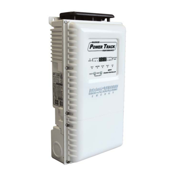
Page 11: Physical Features
Its die cast baseplate with two-piece cover ensures maximum durability with minimum weight for more effi cient operation. As shown in Figure 1-1, the front of the PT-100 charge controller is equipped with the following: PT Mounting Bracket PT Display... -
Page 12: Figure 1-2, Internal Features
USB Micro-B Port – this connector port allows you to download and install updated fi rmware into the PT-100. See Section 5.8 to update the fi rmware in your PT-100. DC Terminal Block – a 4-port terminal block to connect the PV and battery wires. See Section 2.7.8 and 2.7.9 for information on wiring to this terminal block. -
Page 13: Figure 1-3, Side Features
Introduction The sides of the PT-100 charge controller are equipped with the following (Figure 1-3): CE Label – This label means the controller has been tested and conforms to applicable EC directives for emission and immunity—allowing this controller to be sold in Europe. -
Page 14: 2.0 Installation
Before proceeding with the physical installation, read this entire Installation section to determine how best to install your PT-100 charge controller. Also, review the installation instructions for each component in the PV installation. The more you thoroughly plan in the beginning and become familiar with all the components in the installation, the better the chances are that the actual installation process will occur without incident. -
Page 15: Pv System Components
This diagram will help identify the PV system components used with a standalone controller. • PV Array - made up of PV modules and provides DC (solar) power to the PT-100 controller. • PV Strings - an assembly of modules in series that generates DC power at system voltage. -
Page 16: Locating And Mounting The Pt Controller
Installation Locating and Mounting the PT Controller 2.3.1 Removing the Access Cover Before mounting, use a #2 Phillips screwdriver to remove the wiring compartment access cover to expose the mounting holes and wiring terminals. The access cover is secured to the front of the controller with four Phillips #8-32 ×... -
Page 17: Figure 2-4, Pt-100 Dimensions And Knockout Locations
Installation Figure 2-4, PT-100 Dimensions and Knockout Locations Page 8 © 2017 Sensata Technologies... -
Page 18: Figure 2-5, Mounting Orientations
2.3.4 Mounting Orientation The PT-100 must be mounted vertically with the wiring box towards the bottom and its heatsink fi ns oriented vertically to benefi t from convection cooling—DO NOT tilt. The PT-100 has not been tested nor is approved to be mounted in any other orientation. -
Page 19: Figure 2-6, Air Flow In And Around Pt
The fans pull in air through the intake vents and blow out air through the exhaust vents (see Figure 2-6). In order for the PT-100 to provide full output power and to avoid over-temperature fault conditions, do not cover or block the ventilation openings or install this charge controller in an area with limited airfl... -
Page 20: Figure 2-8, Mounting The Pt-100 Controller On A Magnum Panel
2.3.6 Mounting Methods Two mounting methods are available for the PT-100. The fi rst method allows the controller to be mounted next to a Magnum Panel (i.e., MP or MMP), aligning the conduit openings (see Figure 2-8). The second mounting method uses two brackets on the top and bottom of the controller for mounting directly on a wall, and is normally used in a standalone installation (see Figure 2-10). -
Page 21: Figure 2-9, Holes Used To Mount Bracket On Mmp Enclosure
Installation 2.3.6.1.1 Installing the Charge Controller Bracket on a Magnum Panel When a MP or MMP panel is used to mount the PT controller, a bracket is provided to allow the PT controller to be mounted to the side of the panel. This bracket can be easily mounted on either the left or right side of the enclosure. -
Page 22: Figure 2-10, Mounting Bracket Thru-Hole Callouts
PT-100 to be mounted to a vertical surface (wall)—providing the required minimum 1” (2.5 mm) airfl ow clearance behind the controller. Refer to Figure 2-13 for bracket dimensions. -
Page 23: Figure 2-11, Pt Controller Mounting Holes
Installation 2.3.6.2.2 Mounting the Charge Controller on the Wall-mounting Bracket Once the wall-mounting bracket is securely fastened to the vertical surface, you can now attach the PT charge controller. Refer to Figures 2-11 and 2-12. To mount the charge controller to the wall-mounting bracket: Keyhole Details (x2) Top Controller... -
Page 24: Figure 2-12, Surface-Mounting The Pt-100 Controller
Installation PT-100 Two-piece Controller wall-mounting bracket 2x4 stud inside wall Figure 2-12, Surface-mounting the PT-100 Controller 7.75" (19.7 cm) SIDE VIEW 7.19" 1.13" (18.3 cm) (2.9 cm) 6.54" (16.6 cm) FRONT VIEW 6.96" (17.7 cm) 7.59" (19.3 cm) 6.74" (17.1 cm) 4.75"... -
Page 25: Electrical System Wiring Diagrams
Electrical System Wiring Diagrams A diagram of the PV and battery wiring for the PT-100 controller is shown in Figure 2-14 and is provided to assist you or your system installer. Due to the variety of applications and differences in local and national electrical codes, this wiring diagram should only be used as a general guideline. -
Page 26: Pv Voltage Requirements
2.5.1 PV Input Voltage Limits for the PT-100 The following PV voltage levels are required for the PT-100 controller to operate (refer to Table 2-1 and also see Figure 4-8): •... - Page 27 In order to size the PV array so that the output voltage never exceeds the maximum PV input voltage limit on the PT-100, the maximum number of modules in series need to be determined. To do this, you must fi rst determine—from the installation location—the V of the individual module at the lowest expected temperature.
- Page 28 ), and then use this value to fi gure the maximum number of modules that can be connected OC-MAX in series. Find the maximum number of PV modules in series to use with the PT-100 (with αV coeffi cient provided in percentage): Scenario: The module has an open circuit voltage rating of 37.4V...
- Page 29 PV array should normally operate below the High V range of the PT-100, (which is also the upper limit of the MMPT voltage range). The PT-100 will stop operating if the voltage is allowed to rise into the High V range.
- Page 30 MMPT voltage limit of the PT-100. •...
- Page 31 MP-LOW that can be placed in series. Refer to Table 2-1 to fi nd the PT-100’s lower MPPT voltage limit based on the particular battery bank connected to the PT-100. Once the controller’s lower MPPT voltage limit has been determined, divide this value by the calculation and round up to the nearest whole number.
-
Page 32: Conductor Sizing For The Pv System
PV source circuit maximum currents in parallel (I x 1.25 x parallel strings). PT-100 Output Circuit - conductors between the PT-100 and the battery. The maximum current for this circuit is the controller’s maximum output current rating (I = 100ADC). - Page 33 Solar ABCs website (http://solarabcs.org/about/publications/reports/expedited-permit/map/index.html). While the high temperature data is recommended for conductor ampacity sizing, more conservative cold temperature data is recommended when sizing for array voltage (which can damage the PT-100 controller). See the caution note in Section 2.5.2 for more information.
- Page 34 If there is a long wire run between the PV array and the PT-100 controller, or between the PT-100 and the battery bank, larger wire should be used to reduce voltage drop and improve performance.
- Page 35 Installation 2.6.3 Sizing the DC OverCurrent Protection Device (OCPD) The fi nal step necessary in sizing the DC conductor is to verify that the selected conductor can handle the current and is protected by the DC OverCurrent Protection Device (OCPD). Once you have identifi...
- Page 36 Installation 2.6.4 Steps to Sizing Conductors and Overcurrent Protection in a PV System Info: A worksheet to help size PV conductors and overcurrent protection devices using the following steps is provided in Appendix D. Info: Tables referenced in this section are from the 2014 Edition of the National Electrical Code®...
- Page 37 Installation 2.6.4.1 Example to Determine the Size of the PV System Conductors and OCPD’s Find the PV System conductors and OCPD size: Scenario: The PV system will be installed in an area where the average high temperature is 26°C. The array has three PV strings (six current-carrying conductors), these source conductors are bundled together and connect to a fused string combiner.
- Page 38 Continued Scenario: The PV output conductors of the combiner (two current-carrying conductors) run through conduit 2” above the rooftop and connect to a PV disconnect breaker installed in an MMP enclosure with a PT-100 charge controller. The lowest temperature rating of any terminal is 75°C.
-
Page 39: Table 2-2, Allowable Conductor Ampacities
Installation Table 2-2, Allowable Conductor Ampacities The table below shows the allowable ampacities of insulated copper conductors rated 0 through 2000 volts, 60°C through 90°C, not more than three current-carrying conductors in a raceway, cable, or earth (directly buried), based on ambient temperature of 30°C (86°F). Ampacity for Temperature Rating Copper Conductor Conductor Size (AWG) -
Page 40: Table 2-4, Rooftop Distance Adjustments
Installation Table 2-4, Rooftop Distance Adjustments Temperature Adder Distance Above Roof to Bottom of Raceway or Cable (°C) (°F) 0 to 13 mm (0 to ½ in.) Greater than 13 mm (½ in.) to 90 mm (3½ in.) Greater than 300 mm (12 in.) to 900 mm (36 in.) Data taken from Table 310.15(B)(3)(c) in the National Electrical Code®... -
Page 41: Wiring The Pt-100
Installation Wiring the PT-100 This section describes the requirements and recommendations for wiring the PT charge controller. The NEC (National Electric Code, ANSI/NFPA 70) for the United States and the CEC (Canadian Electrical Code) for Canada provide the standards for safely wiring residential and commercial installations. -
Page 42: Table 2-6, Torque Values For The Dc Terminal Block
Installation 2.7.2 Wire Routing Before connecting any wires, determine all wire routes to and from the charge controller, such as: • PV input wiring from the PV array/combiner to the charge controller • Battery output wiring from the charge controller to the batteries •... -
Page 43: Table 2-8, Recommended Dc Wire/Overcurrent Device For Pt-100
For correctly sizing the PV source and PV output conductors (and corresponding overcurrent device) see Section 2.6. For the PT-100 output, use the conductor size listed in Table 2-8, which is based on the PT-100’s maximum output current rating (I = 100 amps). -
Page 44: Table 2-9, Equipment Grounding Conductor Sizing
Figure 1-2, Item 11. Note: The PT-100 is rated for 100 amps full charging output. This output is normally sized with a 125-amp overcurrent device, which would require a 6 AWG (13.3 mm ) copper ground wire. -
Page 45: Figure 2-16, Ground Fault Label
DC system is made within the PT controller through its internal 0.5-amp GFDI fuse. The GFDI fuse inside the PT-100 provides the system negative- to-ground bond and is used to detect ground-faults in a negative grounded PV array system, which is common in North American installations. -
Page 46: Figure 2-17, Wiring To Dc Terminal Block
Info: The charge controller’s PV- and BAT- terminals are electrically connected to each other internally and either connection can be used for the input or output negative. IRING COMPARTMENT 2 3 4 5 6 7 8 9 (PT-100) YSTEM ROUND rounding Electrode Conductor (GEC) - Page 47 Installation 2.7.9 Steps to Wiring the PT-100 The following steps are basic guidelines for connecting PV and battery wiring to and from the PT- 100 charge controller. Remove the four Phillips screws on the wiring access cover to access the terminal block (see Figure 2-2).
-
Page 48: Wiring The Battery Temperature Sensor
Installation Wiring the Battery Temperature Sensor The Battery Temperature Sensor (BTS) shown in Figure 2-18, allows the charge controller to automatically adjust the charge voltage set-points to correctly charge the batteries under extreme temperature changes. If the temperature sensor is NOT installed and the batteries are subjected to large temperature changes, the life of the battery may be shortened. -
Page 49: Wiring The Auxiliary Relay
When the PT controller is confi gured as a standalone controller, this aux relay only engages when there is a controller fault. When the PT-100 is networked to a Magnum inverter and using a Version 4.0 remote (ME-ARC or ME-ARTR), this relay can indicate when a PT controller fault has occurred or be programmed to automatically engage or disengage based on high or low battery voltage. -
Page 50: 2.10 Network Wiring
MP enclosure must be rated for 240 volts or higher to be code compliant. With the purchase of the PT-100, three six-foot, yellow communication cables with 300-volt rated insulation are provided. These communications cables—shown below—are provided to make the connections between the PT controller and any... -
Page 51: Table 2-10, Remote Compatibility Version
ME-RTR ≥ Version 2.0 Note 1: The ME-RC can be used and will communicate with the PT-100’s to allow them to be stacked. However, it does not allow any monitoring or adjustments to the PT controller. Note: To view the remote’s software version level, push the TECH button on your remote and access the Revisions/Versions menu. -
Page 52: Figure 2-25, Networking To Accessories (Daisy Chain Confi Gurations)
Note: The ME-AGS-N or PT-100 must be the fi rst network device connected to the inverter, Note: The ME-AGS-N or PT-100 must be the first network device connected to the inverter, followed by the ME-BMK, followed by the ME-BMK, and whatever device wasn’t used as the fi rst network device (ME- and whatever device wasn’t used as the first network device (ME-AGS-N or PT-100) is connected after the ME-BMK. -
Page 53: Figure 2-26, Networking To Accessories (Star Confi Gurations)
Installation Networking the PT-100 with Other Network Devices (Star Configuration using two 2-way splitters) Networking the PT-100 (Star Confi guration using 2-way splitters) Magnum PT-100 Inverter/charger CHARGE CONTROLLER ME-ARC ADVANCED REMOTE Two 2-way Phone-splitters ME-BMK BATTERY MONITOR ME-AGS-N NETWORK AGS Networking the PT-100 (Star Confi... -
Page 54: 2.11 Stacking Installation - Wiring Multiple Pt Controllers Together
• Ensures all stacked controllers turn off if a ground fault occurs on a single PT-100 controller. Stack Installation Requirements When connecting PT controllers together in a stacked system confi guration, certain installation requirements have to be met to allow proper communication and charging operation. - Page 55 When multiple inverters are stacked together, all the inverters charge to the Master inverter’s target voltage; and any inverter in a stacked confi guration can be networked to any stacked PT-100. However, be aware that the inverters may have a variance in their battery voltage measurement, and because of this, the inverter with the lowest battery voltage reading won’t reduce its current...
-
Page 56: Figure 2-27, Wiring Multiple Controllers
OSITIVE Magnum Remote REMOTE Cable (300V) Int ernal To PT-100 Master 1 2 3 4 5 6 7 8 9 1 2 3 4 5 6 7 8 9 1 2 3 4 5 6 7 8 9 GFDI fuse... -
Page 57: Figure 2-28, Networking Multiple Pt Controller's
Installation STACK Cable STACK Cable Page 48 © 2017 Sensata Technologies... -
Page 58: Figure 2-29, Networking Multiple Pt Controller's With Multiple Inverter's
Installation STACK Cable STACK © 2017 Sensata Technologies Page 49... -
Page 59: 2.12 Final Inspection/Tests
Vbat + 200VDC (or 240VDC maximum) and the polarity of the PV voltage to the controller is correct. 4. If the PV voltage is within the PT-100 input requirements and the polarity is correct, then close the PV disconnect breaker to apply PV power to the charge controller’s PV input. After the PV input power is qualifi... -
Page 60: Figure 2-30, Power-Up Test Displays
(i.e., 12, 24 or 48 volts) is incorrect for your battery bank, change DIP switches 3 and 4 to the correct nominal voltage setting (see Section 3.1) and re-power/re-boot the PT-100 to allow the new DIP switch setting to take effect. PT-100... -
Page 61: 3.0 Setup
Setup 3.0 Setup When the PT controller is not connected to a Magnum inverter/remote, the internal DIP switch (Figure 1-2, Item 4) is used to determine the PT controller’s operation. Info: When the PT controller is connected and networked with a Magnum inverter and remote, the remote is used to set up and/or control the PT controller’s operation. -
Page 62: Table 3-1, Battery Type To Charge Voltages
Setup Switches 3 & 4: System’s Battery Voltage Four (4) settings are available for your system’s nominal battery voltage as shown below. Use the auto voltage detection setting (default) to determine the system voltage automatically when the battery is connected to the PT controller; or, if the battery is out of its nominal voltage range (i.e., highly discharged), select the setting that matches the system’s nominal battery voltage. - Page 63 See Sections 2.11 and 4.13 for information on stacking controllers. Absorption Charge Time When the PT-100 controller is NOT networked, eight (8) time periods are provided to determine how long the controller is in the Absorption Charge stage—holding the batteries at the Absorb Voltage setting.
-
Page 64: Table 3-2, Summary Of Dip Switch Position
Setup Table 3-2, Summary of DIP Switch Position DEFAULT SETTING (all switches down) DOWN (DN) Switch Function Switch Position Enabled SW1 DN ARC Fault Detection Disabled SW1 UP Enabled SW2 DN Ground Fault Detection Disabled SW2 UP Auto Detect SW3 DN SW4 DN 12V System SW3 DN... -
Page 65: 4.0 Operation
Operation 4.0 Operation This section explains how the controller operates, and also provides information on the LED indicators and the digital display that are used to show the operational status of the PT controller. 3-Character PT Fault Display with LED Indicator LED Indicators Charge Status AUX Relay... -
Page 66: Front Panel Operation
Operation Front Panel Operation When power is applied, the display on the PT controller goes through a power-up test routine (see Figure 2-30). Once the power-up test is complete and no faults occur, the controller begins operating and the display begins automatically scrolling through the operational displays (see Figure 4-2). 4.2.1 Operational Displays The operational displays provide information on the PV voltage and power, the battery voltage... -
Page 67: Table 4-1, Charge Status Led Indicators
Operation 4.2.2 Charge Status Indicators The charge status LED indicators on the front panel indicate the charge status of the controller. The table below describes the charge stage of the controller and the charger operation—depending on what the charge status LED’s are doing. Charge Status Indicators Figure 4-3, Charge Status Indicators... -
Page 68: Table 4-2, Power Status Code Descriptions
Operation 4.2.3 Power Status Codes The digital display shows a P-number (P##) to indicate the status of the PV power delivered to the battery—through the controller. Table 4-2 lists each Power Status Code and its description. Info: If the display is auto-scrolling, the power status only shows if the power output is being limited (P03 - P05), otherwise only the fi... -
Page 69: Figure 4-4, Hard Fault Conditions
Operation 4.2.4 Fault Indicator Whenever a fault condition occurs, the red FAULT indicator illuminates (comes on or blinks) and a fault code (F##) is displayed. Info: If a fault code (F##) is displayed, refer to Section 5.3 to determine and troubleshoot the fault condition. -
Page 70: Figure 4-7, Select And Reset Pushbuttons
Operation 4.2.6 Display/LED Indicator Summary • PV VOLTS (green) is ON = displays the input voltage from the PV array. • PV KW (green) is ON = displays the PV array power (in kilo-watts) to the battery bank. • Battery VOLTS (green) is ON = displays the voltage of the battery bank. •... -
Page 71: Mppt Operation
(I) and voltage (V) are optimized at the same time—referred to as the Maximum Power Point (MPP). The MMPT algorithm in the PT-100 is designed to sample the output of the PV array and adjust the load it presents to the PV array until the voltage and current approaches the MPP. -
Page 72: Charger Control Operation
Operation Charger Control Operation As a charge controller, the PT-100’s primary function is to monitor and charge the batteries appropriately when PV power is available, and to prevent the batteries from being overcharged. When PV power is connected to the PV input, the charge controller begins monitoring for acceptable PV power and begins charging the batteries once it has accepted the PV input. - Page 73 Operation 4.4.1 Equalizing the Battery Bank Equalizing (EQ) is a “controlled overcharge” of a lead-acid battery (or battery bank) done to help the battery reach and maintain peak capacity. This controlled overcharging helps equalize the chemistry in the individual battery cells by mixing the battery electrolyte (to reverse the buildup of stratifi...
-
Page 74: Ground Fault Detection And Interruption (Gfdi) Operation
Operation 4.4.2 Starting or Stopping an Equalization Charge Cycle See Table 3-1 to determine the equalize voltage for your battery type. Equalize charging can only be enabled if the Battery Type setting allows. Info: Equalization charging is available if FLOODED or AGM 1 is selected as the Battery Type (DIP switches 5 and 6), it is not available if GEL or AGM 2 is selected. -
Page 75: Arc-Fault Protection Operation
Operation Arc-Fault Protection Operation Arcs are caused by an intermittent connection and are dangerous because they are not an overload or short-circuit, so the overcurrent protective device does not operate; however, they can burn through wiring insulation or ignite nearby combustibles. The PT controller has an integrated Arc-Fault Protection (AFP) circuit, which provides additional protection against fi... -
Page 76: Battery Temperature Sensor Operation
Operation Battery Temperature Sensor Operation The plug-in Battery Temperature Sensor (BTS) is used to determine the battery’s temperature. This information allows the multi-stage battery charger to automatically adjust the battery charge voltages for optimum charging performance and longer battery life. With a BTS installed, the controller will adjust the absorb and fl... -
Page 77: Charge Controller Fan Operation
Info: The temperature sensed by the BTS does not determine whether the charge controller’s fans start or stop. Info: The PT-100 delivers full output current (100 amps) in ambient temperatures up to 40°C (104°F). Due to the fan cooling, this level of performance can be achieved in closed rooms. -
Page 78: 4.10 Auxiliary Relay Operation
Operation 4.10 Auxiliary Relay Operation When the PT controller is confi gured as a standalone device (i.e., not networked with a Magnum inverter/remote), the internal aux relay stays disengaged during normal operation, but engages when a PT controller fault is detected. If the PT controller is networked (i.e., connected to a Magnum inverter and remote), the aux relay can be programmed to manually open or close, work as an automatic voltage-controlled relay (opens or closes based on VDC and activates either as an active high or active low type relay with... -
Page 79: Operating Confi Guration - Standalone Vs Networked
4.12 Operating Confi guration - Standalone vs Networked The operating confi guration in the PT-100 controller uses default settings that are adequate for most installations (shown in Table 4-3 and described below). When the controller is confi gured as a standalone controller, the controller’s internal DIP switch is used to adjust these settings. -
Page 80: Stacking Operation
Operation 4.13 Stacking Operation This section provides information on how to identify stacked controllers, and how they communicate between each other and with the network remote. 4.13.1 Viewing the Controllers Network Address - Stacked Confi guration When multiple PT controllers are connected/networked together in a stacked confi guration, the controller confi... - Page 81 Operation 4.13.2 Network Communication between each Stacked Controller When multiple PT controllers are networked together in a stacked confi guration per Section 2.11 (Stacking Installation - Wiring Multiple PT Controllers Together), they operate as listed below: 1. The controller confi gured with the lowest network address (using DIP switches 7, 8, and 9) is the master controller and all other controllers networked together become slave controllers (and therefore follow the master).
- Page 82 CTRL start command and see if the command is performed by all the PT-100’s. This is done by pressing the CTRL button on the remote and rotating the SELECT knob to the PT Control menu. Then press the SELECT knob to enter a CTRL ‘Start’ command such as: Start Float or Start Bulk.
-
Page 83: 5.0 Maintenance And Troubleshooting
Normal operation resumes when the battery is reconnected. Periodic Maintenance The PT-100 charge controller is designed to provide you with years of trouble-free service. The following information is provided to help you keep your PT-100 charge controller in optimum operational condition. -
Page 84: Basic Troubleshooting
Maintenance and Troubleshooting Basic Troubleshooting The PT-100 charge controller is a fairly simple device to troubleshoot. The following chart is designed to help you quickly pinpoint the most common charge controller failures. If a fault code (F##) is shown on the display, refer to Sections 5.3 and 5.4. - Page 85 Maintenance and Troubleshooting High PV Input Fault - The PT controller turned off and stopped producing power to the batteries because a very high PV voltage (>187 VDC) has been detected on the PV input terminals (i.e., PV+ to PV-). This is usually caused during cold weather if the PV array voltage is sized too high or too close to the maximum PT input operating voltage.
- Page 86 Maintenance and Troubleshooting High Battery Temp Fault - The PT controller turned off because the temperature around the BTS has reached a temperature greater than 54°C/129°F. Remedy: Check the area where the BTS is located; if placed on a battery, ensure the connection to the battery terminal is tight, that the batteries are not overheated, or that the BTS hasn’t been placed in a hot area or near a hot device.
- Page 87 Maintenance and Troubleshooting GFDI Fault - The GFDI fuse in the PT controller has opened due to a ground-fault condition. Note: If the GFDI detection is not required, set DIP switch 2 to UP. Remedy: Correct the ground-fault condition and replace the fuse (see Section 5.5).
-
Page 88: Stacking Fault Codes
Maintenance and Troubleshooting Stacking Fault Codes When multiple PT controllers are connected together in a stacked confi guration, additional fault conditions can be detected and will appear in the digital display to identify the problem. The following table describes each fault code (F2#) and any corrective actions to be taken for each code. Table 5-3, Stack Fault Code Descriptions No Stack Comm - The PT controller will not run because stacking has been ... - Page 89 Maintenance and Troubleshooting Table 5-3, Stack Fault Code Descriptions (continued) Stack Switch Fault - The PT controller is not able to run because the controller’s stacking address has been incorrectly set. Remedy: 1. Ensure the stacking address is not set to C00. a.
-
Page 90: Removing/Replacing The Gfdi Fuse
Maintenance and Troubleshooting Removing/Replacing the GFDI Fuse WARNING: Dangerous voltages can exist inside the controller. Disconnect all PV and battery circuits to the PT controller before removing or installing the GFDI fuse. The PT controller has internal capacitors that remain charged after disconnecting all sources of power. -
Page 91: Removing And Replacing The Electronics Section
Remove two #8 x ¾” Phillips head screws PT-100 Mounting Controller Bracket (Electronics Section) Remove two #8/32 x 3/8” Phillips head screws PT-100 Controller (Wiring/Conduit Box) Leave in place Figure 5-2, Electronics Section Removal Page 82 © 2017 Sensata Technologies... -
Page 92: Resetting The Pt-100 Charge Controller
Maintenance and Troubleshooting Resetting the PT-100 Charge Controller Certain conditions—such as clearing an internal fault—require that the PT-100 be reset. Most times a software reset (also known as a soft reset) is suffi cient, otherwise a power reset is (also known as a hard reset) is required. -
Page 93: Updating The Pt-100'S Firmware
Maintenance and Troubleshooting Updating the PT-100’s Firmware Firmware updates for the PT-100 are provided to improve performance, fi x issues, and to add new features or change functionality. Firmware updates are periodically available for download on our website (www.SensataPower.com). This website also provides an Instruction Sheet that gives a detailed step-by-step procedure for successfully downloading and installing the update. -
Page 94: Appendix A - Specifi Cations
Appendix A – Specifi cations Appendix A – Specifi cations PT-100 Charge Controller Specifi cations Electrical Specifi cations Maximum PV Input Voltage 200VDC + battery voltage or 240VDC (any condition) –whichever is lower PV Operating Voltage (VBat + 8V) to 187 VDC... -
Page 95: Figure A-1, Ambient Temperature Vs Continuous Current Curve
Performance Graphs A-2.1 Ambient Temperature verses Continuous Current As the temperature of the power devices inside the PT-100 increases, the maximum allowable charger current is reduced. The following curve shows the effect of charger current with the temperature above 40°C. -
Page 96: Figure A-3, Maximum Power Vs Mpp Voltage Curve
Appendix A – Specifi cations A-2.3 Maximum Power verses MPP Voltage The following curve shows the PT-100’s output power at different PV input MMP voltage levels. The output power of the PT-100 is consistent throughout it’s PV input MMP voltage range. PT-100 vs Competition... -
Page 97: Appendix B - Optional Equipment And Accessories
Appendix B – Optional Equipment Appendix B – Optional Equipment and Accessories The following components are available for use with the PT-100 Series charge controller. Some of these items are required. Depending upon the intended use of the charge controller. -
Page 98: Appendix C - Charge Controller Terminology
Photovoltaic (PV) – Solar powered. Resistance (Ohms) – Slows the electrical fl ow of direct current (DC). Stacking (PT-100’s) - Multiple charge controllers operating together to charge and regulate the battery voltage. Stratifi cation – Over time, a battery’s electrolyte (liquid) tends to separate. The electrolyte at the top of the battery becomes watery, while at the bottom it becomes more acidic. -
Page 99: Appendix D - Pv Conductor And Ocpd Sizing Worksheet
Breaker PV Source PV Output PV Controller Standalone Inverter Standalone Inverter (PT-100) Input Circuit Output Circuit PV Circuits: PV Source [1] and PV Output [2] Output Circuit Sizing Conductors and Overcurrent Protection Device Ratings in the PV System To calculate the required conductor and overcurrent protection device sizes, follow these steps:... - Page 100 Appendix D – Sizing Worksheet b) Find the PV circuit’s conductor size after derating factors have been applied: Look at Table 310.15(B)(16) and select the insulation temperature rating column that corresponds to the lowest temperature rating of any terminal the conductor is terminated on, regardless of the insulation of the selected conductor.
-
Page 101: Appendix E - Warranty And Service Information
Appendix E – Warranty and Service Information Limited Warranty Sensata Technologies warrants the PT-100 to be free from defects in material and workmanship that may result in product failure during normal usage, according to the following terms and conditions: 1. The limited warranty for the product extends for 60 months beginning from the product’s original date of purchase. - Page 102 Magnum Energy Products Manufactured by: Sensata Technologies www.SensataPower.com PT-100 Owner’s Manual (PN: 64-0067 Rev B)
Need help?
Do you have a question about the PT-100 and is the answer not in the manual?
Questions and answers