Sign In
Upload
Manuals
Brands
Magnum Energy Manuals
Controller
PT-100
Magnum Energy PT-100 Manuals
Manuals and User Guides for Magnum Energy PT-100. We have
1
Magnum Energy PT-100 manual available for free PDF download: Owner's Manual
Magnum Energy PT-100 Owner's Manual (102 pages)
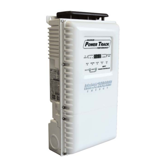
MPPT Charge Controller
Brand:
Magnum Energy
| Category:
Controller
| Size: 8 MB
Table of Contents
Disclaimer of Liability
2
Restrictions on Use
2
Copyright Notice
2
Document Information
2
Contact Information
2
Important Safety Instructions
3
Consignes de Sécurité Importantes
5
Table of Contents
7
1 0 Introduction
10
Key Features and Benefi Ts
10
Regulatory Compliance
10
Physical Features
11
Figure 1-1, Front Features
11
Figure 1-2, Internal Features
12
Figure 1-3, Side Features
13
2 0 Installation
14
Pre-Installation
14
PV System Components
15
Figure 2-1, Simplifi Ed PV System
15
Locating and Mounting the PT Controller
16
Figure 2-2, Removing the Access Cover
16
Figure 2-3, Removing Knockouts
16
Figure 2-4, PT-100 Dimensions and Knockout Locations
17
Figure 2-5, Mounting Orientations
18
Figure 2-6, Air Flow in and Around PT
19
Figure 2-7, Minimum Mounting Clearance Requirements
19
Figure 2-8, Mounting the PT-100 Controller on a Magnum Panel
20
Figure 2-9, Holes Used to Mount Bracket on MMP Enclosure
21
Figure 2-10, Mounting Bracket Thru-Hole Callouts
22
Figure 2-11, PT Controller Mounting Holes
23
Figure 2-12, Surface-Mounting the PT-100 Controller
24
Figure 2-13, Mounting Bracket Dimensions (Each)
24
Electrical System Wiring Diagrams
25
Figure 2-14, PT-100 Controller - System Wiring
25
PV Voltage Requirements
26
Table 2-1, PV Input Voltage Parameters
26
Conductor Sizing for the PV System
32
Figure 2-15, Standalone PV System Circuits
32
Table 2-2, Allowable Conductor Ampacities
39
Table 2-3, Ambient Temperature Adjustments
39
Table 2-4, Rooftop Distance Adjustments
40
Table 2-5, Multiple Conductors in Raceway/Cable Adjustments
40
Wiring the PT-100
41
Table 2-6, Torque Values for the DC Terminal Block
42
Table 2-7, Torque Values for the Ground Busbar
42
Table 2-8, Recommended DC Wire/Overcurrent Device for PT-100
43
Table 2-9, Equipment Grounding Conductor Sizing
44
Figure 2-16, Ground Fault Label
45
Figure 2-17, Wiring to DC Terminal Block
46
Wiring the Battery Temperature Sensor
48
Figure 2-18, Battery Temperature Sensor
48
Figure 2-19, BTS and Battery Cable Hardware Installation
48
Wiring the Auxiliary Relay
49
Figure 2-20, Auxiliary Relay Connections and Example
49
2.10 Network Wiring
50
Figure 2-21, NETWORK Communication Cable (300V Rated)
50
Figure 2-22, Extension Cable (300V Rated)
50
Figure 2-23, Stacking Cable (300V Rated)
50
Table 2-10, Remote Compatibility Version
51
Figure 2-24, Connecting the PT-100 to the Magnum Inverter
51
Figure 2-25, Networking to Accessories (Daisy Chain Confi Gurations)
52
Figure 2-26, Networking to Accessories (Star Confi Gurations)
53
2.11 Stacking Installation - Wiring Multiple PT Controllers Together
54
Figure 2-27, Wiring Multiple Controllers
56
Figure 2-28, Networking Multiple PT Controller's
57
Figure 2-29, Networking Multiple PT Controller's with Multiple Inverter's
58
2.12 Final Inspection/Tests
59
Figure 2-30, Power-Up Test Displays
60
3 0 Setup
61
Adjust DIP Switch Settings
61
Figure 3-1, DIP Switch Settings
61
Table 3-1, Battery Type to Charge Voltages
62
Table 3-2, Summary of DIP Switch Position
64
4 0 Operation
65
PT Front Panel Features
65
Figure 4-1, Front Panel Display and LED Indicators
65
Front Panel Operation
66
Figure 4-2, Scroll Sequence of Screens
66
Table 4-1, Charge Status LED Indicators
67
Figure 4-3, Charge Status Indicators
67
Table 4-2, Power Status Code Descriptions
68
Figure 4-4, Hard Fault Conditions
69
Figure 4-5, Soft Fault Conditions
69
Figure 4-6, Aux Relay Indicator
69
Figure 4-7, SELECT and RESET Pushbuttons
70
MPPT Operation
71
Figure 4-8, I-V Curve
71
Charger Control Operation
72
Figure 4-9, Automatic 3-Stage Charging Graph
72
Ground Fault Detection and Interruption (GFDI) Operation
74
Figure 4-10, Start/Stop Equalize Charge
74
Arc-Fault Protection Operation
75
Figure 4-11, AFP Test Switch
75
Battery Temperature Sensor Operation
76
Figure 4-12, BTS Temperature to Charge Voltage Change
76
Charge Controller Fan Operation
77
Powersave Operation
77
Figure 4-13, Power Save Indication
77
4.10 Auxiliary Relay Operation
78
Internal Beeper Operation
78
Operating Confi Guration - Standalone Vs Networked
79
Table 4-3, Controller Settings (Standalone Vs Networked)
79
Stacking Operation
80
Figure 4-14, Viewing Network Address - Stacked Controller
80
5 0 Maintenance and Troubleshooting
83
Periodic Maintenance
83
Basic Troubleshooting
84
Troubleshooting Based on Fault Codes
84
Table 5-1, Basic Controller Troubleshooting (Remote Not Available)
84
Table 5-2, Fault Code Descriptions
84
Stacking Fault Codes
88
Table 5-3, Stack Fault Code Descriptions
88
Removing/Replacing the GFDI Fuse
90
Figure 5-1, GFDI Fuse Location (Access Cover Removed)
90
Removing and Replacing the Electronics Section
91
Figure 5-2, Electronics Section Removal
91
Resetting the PT-100 Charge Controller
92
Figure 5-3, PT Controller Reset
92
Updating the PT-100'S Firmware
93
Figure 5-4, PT-100'S Firmware Update Connection Port
93
Appendix A - Specifi Cations
94
Figure A-1, Ambient Temperature Vs Continuous Current Curve
95
Figure A-2, Output Current Vs Battery Voltage Curve
95
Figure A-3, Maximum Power Vs MPP Voltage Curve
96
Appendix A - Specifi Cations
97
Appendix B - Optional Equipment and Accessories
97
Appendix C - Charge Controller Terminology
98
Appendix D - PV Conductor and OCPD Sizing Worksheet
99
Appendix E - Warranty and Service Information
101
Limited Warranty
101
How to Receive Repair Service
101
Advertisement
Advertisement
Related Products
Magnum Energy ME-AGS-N
Magnum Energy Categories
Inverter
Remote Control
Battery Charger
Adapter
Measuring Instruments
More Magnum Energy Manuals
Login
Sign In
OR
Sign in with Facebook
Sign in with Google
Upload manual
Upload from disk
Upload from URL