Table of Contents
Advertisement
Advertisement
Table of Contents
Troubleshooting

Subscribe to Our Youtube Channel
Related Manuals for Magnum Energy ME-AGS-N

Summary of Contents for Magnum Energy ME-AGS-N
- Page 2 Disclaimer of Liability Restrictions on Use Copyright Notice Document Information Contact Information Statement of Appreciation © 2012 Magnum Energy, Inc.
- Page 3 Important Safety Instructions Safety Symbols WARNING: CAUTION: Info: Remedy: Product Safety Alerts WARNING: WARNING: WARNING: WARNING: © 2012 Magnum Energy, Inc.
-
Page 4: Table Of Contents
2.0 Installation 3.0 ME-AGS-N Module Setup 4.0 ME-AGS-N Module Functional Tests 5.0 ME-AGS-N Module Operation 6.0 ME-AGS-N Module Troubleshooting 7.0 Using a Remote with the ME-AGS-N 8.0 Using the ME-RC Remote 9.0 Using the ME-ARC Remote © 2012 Magnum Energy, Inc. - Page 5 List of Contents (cont.) 10.0 Using the ME-RTR Router 11.0 ME-AGS-N Remote Status Messages ........84 12.0 ME-AGS-N Remote Troubleshooting........89 13.0 Appendix 14.0 Limited Warranty List of Tables © 2012 Magnum Energy, Inc.
- Page 6 List of Figures © 2012 Magnum Energy, Inc.
-
Page 7: Introduction
1.0 Introduction 1.0 Introduction • Battery Voltage: • Time of Day: • Inverter Load Amps: Note: • Rising Temperature: • Battery SOC: Note: Info: 1.1 ME-AGS-N Module Info: Info: ME-AGS-S © 2012 Magnum Energy, Inc. - Page 8 1.0 Introduction 1.2 ME-AGS-N System Requirements Automatic Start Generator Info: Remote Control Magnum Inverter 1.3 ME-AGS-N Components 1.3.1 ME-AGS-N Features STATUS Indicator TEST Button Wiring Terminal Block Mounting Flange © 2012 Magnum Energy, Inc.
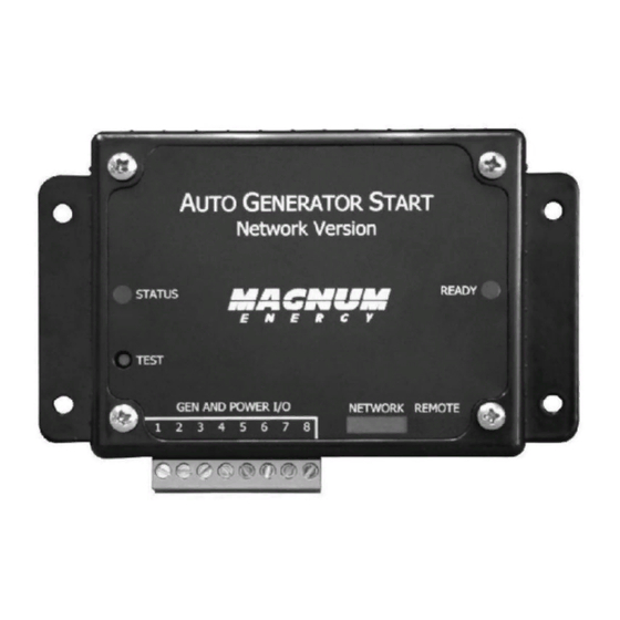
- Page 9 1.0 Introduction READY Indicator NETWORK Connection Port (green label) REMOTE Connection Port (purple label) Internal Access Screws Figure 1-1, Components of the ME-AGS-N Module Figure 1-2, Remote Temp Sensor Cable (60 ft.) © 2012 Magnum Energy, Inc.
-
Page 10: Installation
2.0 Installation 2.0 Installation WARNING: CAUTION: CAUTION: 2.1 Installation Requirements © 2012 Magnum Energy, Inc. - Page 11 2.0 Installation FAULT SELECT ON/OFF CHARGER ON/OFF INVERTER SHORE METER SETUP TECH Figure 2-1, ME-AGS-N System Diagram © 2012 Magnum Energy, Inc.
- Page 12 (4.8 mm) 5 ” ” (136.6 mm) 3 ” (69.9 mm) (82.6 mm) 2 ” 3 ” (50.8 mm) (92.8 mm) ” (9.5 mm) 4 ” (108 mm) 4 ” (123.9 mm) Figure 2-2, ME-AGS-N Dimensions © 2012 Magnum Energy, Inc.
- Page 13 2.4.1 Connecting the Remote Temp Sensor Cable Note: ME-AGS-N Remote Temp Sensor cable Figure 2-3, Remote Temp Sensor Connection 2.4.2 Connecting the Network Communication Cable Note: 4-conductor telephone-type same same color color Figure 2-4, Network Communication Cable © 2012 Magnum Energy, Inc.
- Page 14 Large inverter (ME, RD, MS, MS-PAE Series) Small Magnum inverter ME-AGS-N DC 12.6V Remote Figure 2-5, Connecting the AGS to a Magnum Inverter (Small) ME-AGS-N Large Magnum inverter Remote DC 12.6V Figure 2-6, Connecting the AGS to a Magnum Inverter (Large) © 2012 Magnum Energy, Inc.
- Page 15 Daisy Chain Confi guration ME-AGS-N (1 device) Remote Control Magnum Inverter/Charger FAULT 12.6V SELECT ON/OFF Phone CHARG ER ON/OFF splitter INVERTER SHORE METER SETUP TECH ME-BMK (2 device) Figure 2-8, Multiple Network Devices – Daisy Chain Confi guration © 2012 Magnum Energy, Inc.
- Page 16 2.0 Installation 2.4.4 Ensure all Negative Connections are Connected Together Figure 2-9, Connected Devices at the Same Potential 2.5 ME-AGS-N Terminal Block Wiring Connections CAUTION: CAUTION: Info: 2.5.1 Power Connections (Terminals 3 & Info: © 2012 Magnum Energy, Inc.
- Page 17 Gen Type is 2-Wire Standby Mode* • Gen Type is not 2-Wire Standby Mode To install the generator’s run sense voltage to the AGS: Info: What if my generator does not have a gen run sense output? © 2012 Magnum Energy, Inc.
- Page 18 2.0 Installation Alternative Option 1 1 2 3 4 5 6 7 8 Alternative Option 2 Alternative Option 3 Figure 2-10, Generator Run Sense Options © 2012 Magnum Energy, Inc.
- Page 19 2.5.3 Gen Start/Stop Connections (Terminals 1, 5, 6, 7, & CAUTION: The warranty does not cover damage to these relays. Info: Info: Info: • Relay 1 (RY1) and Relay 2 (RY2) • Relay 3 (RY3) © 2012 Magnum Energy, Inc.
- Page 20 2.0 Installation 2 3 4 5 6 7 8 Figure 2-11, Wiring to the ME-AGS-N Module’s Terminal Block © 2012 Magnum Energy, Inc.
- Page 21 This electrical system is equipped with an Automatic Generator Starting device and/or an inverter. Disconnect all AC and DC power to the ME-AGS-N and/or inverter before performing any service to the electrical system. Failure to do so can result in shock causing serious injury or death.
- Page 22 2.0 Installation Figure 2-13, Two-wire Control Type Generators © 2012 Magnum Energy, Inc.
- Page 23 2.0 Installation Figure 2-14, Three-wire Momentary Control Type Generators © 2012 Magnum Energy, Inc.
- Page 24 2.0 Installation Figure 2-15, Three-wire Maintain Control Type Generators © 2012 Magnum Energy, Inc.
-
Page 25: Me-Ags-N Module Setup
3.0 ME-AGS-N Module Setup 3.0 ME-AGS-N Module Setup 3.1 Confi guring the Internal ME-AGS-N Settings Figure 3-1, Inside the ME-AGS-N Module Input DC Voltage Jumper Setting 12 VDC Operation 48 VDC Operation 24 VDC Operation Figure 3-2, DC Voltage Settings... - Page 26 3.0 ME-AGS-N Module Setup Table 3-1, Gen Type Settings Type QD Mode 3-Wire Mode Portable Mode 2-Wire Momentary Mode 2-Wire Maintain Mode 2-Wire Standby Mode* 5-Wire Mode © 2012 Magnum Energy, Inc.
-
Page 27: Me-Ags-N Module Functional Tests
4.0 ME-AGS-N Module Functional Tests 4.0 ME-AGS-N Module Functional Tests Note: 4.1 Power-Up Test Info: 4.2 Generator Wiring Test ¹ Note: Info: Note¹: © 2012 Magnum Energy, Inc. -
Page 28: Me-Ags-N Module Operation
5.1 ME-AGS-N Module TEST Pushbutton Note: 5.2 ME-AGS-N Module LED Indicators 5.2.1 STATUS LED Indicator Blinking Green: Solid Green: Solid Red: 5.2.2 READY LED Indicator Solid Green: Blinking Green: Note: Figure 5-1, ME-AGS-N Front Panel Controls and Indicators © 2012 Magnum Energy, Inc. -
Page 29: Me-Ags-N Module Troubleshooting
6.0 ME-AGS-N Module Troubleshooting 6.0 ME-AGS-N Module Troubleshooting 6.1 Using the ME-AGS-N’s LED Indicators WARNING: Table 6-1, ME-AGS-N Module Troubleshooting Guide Symptom Solution Indication Note: © 2012 Magnum Energy, Inc. - Page 30 6.0 ME-AGS-N Module Troubleshooting 6.2 Generator Starting/Running Troubleshooting 6.2.1 If the Generator will not Start or Run 6.2.2 STATUS LED does not go Solid Info: • Gen Type is 2-Wire Standby Mode Note: © 2012 Magnum Energy, Inc.
- Page 31 6.0 ME-AGS-N Module Troubleshooting • Gen Type is not 2-Wire Standby Mode Note: © 2012 Magnum Energy, Inc.
-
Page 32: Using A Remote With The Me-Ags-N
7.0 Using a Remote with the ME-AGS-N 7.0 Using a Remote with the ME-AGS-N 7.1 AGS to Inverter Compatibility Table 7-1, AGS Compatibility Matrix Chart Inverter Remote Control / Level Revision Required AGS Feature Required ME-RC ME-ARC ME-RTR © 2012 Magnum Energy, Inc. - Page 33 7.0 Using a Remote with the ME-AGS-N 7.2 Software Differences Between AGS Revisions Info: Table 7-2, AGS Revision Differences ME-AGS-N Revision Revision Changes Can I upgrade the software on my ME-AGS-N? Note: © 2012 Magnum Energy, Inc.
-
Page 34: Using The Me-Rc Remote
8.0 Using the ME-RC Remote 8.0 Using the ME-RC Remote DC 12.6V AGS and TECH Buttons Figure 8-1, ME-RC’s AGS Confi guration Access Buttons Info: 8.1 ME-AGS-N Setup using the ME-RC Note: Table 8-1, ME-RC Autostart/Autostop Matrix Autostart See AGS Page... - Page 35 8.0 Using the ME-RC Remote Table 8-2, Software Differences Between ME-RC Revisions AGS Menu AGS Menu Inverter ME-AGS-N ME-RC (Button: Menu) Selections/Adjustments Level Required Required © 2012 Magnum Energy, Inc.
- Page 36 Using low battery voltage to autostart: Table 8-3, Battery AmpHrs Capacity to Suggested Gen Run Time Battery Battery Suggested Suggested AmpHrs AmpHrs Gen Run Time Gen Run Time Capacity Capacity AGS: 04 Start Temp F Menu Info: © 2012 Magnum Energy, Inc.
- Page 37 8.0 Using the ME-RC Remote • 65F - 95F • Ext Input Default setting: Range: Why should I use Start Temp? Where should I set Start Temp? Info: © 2012 Magnum Energy, Inc.
- Page 38 AGS: 05 Start Volts Menu Default setting: Range: Info: Where should I set Start Volts? Info: AGS: 06 Set Time Menu Info: To set the current time: • Hour • Minute • AM-PM AGS: 07 Quiet Time Menu Info: © 2012 Magnum Energy, Inc.
- Page 39 Default setting: Range: Why should I use Quiet Time? Where should I set Quiet Time? 8.2 ME-AGS-N Functional Tests using the ME-RC 8.2.1 Remote to Generator Communication Test 8.2.1.1 Determining AGS Status 8.2.1.2 Starting the Generator from the Remote Note: Info: ©...
- Page 40 8.0 Using the ME-RC Remote 8.3 ME-AGS-N Operation/Monitoring using the ME-RC 8.3.1 Controlling the AGS using the ME-RC AGS: 01 AGS Control Menu • Info: • Enable • Test • Enable w/QT WARNING: 8.3.2 Monitoring the AGS using the ME-RC AGS: 02 AGS Status Menu ©...
- Page 41 8.0 Using the ME-RC Remote Info: Info: Note: AGS: 08 AGS TECH Menu • Gen Run • AGS VDC • Temp • AGS Rev Info: • AGS Mode ¹ Default setting: Settings: Info: Info: Note¹ © 2012 Magnum Energy, Inc.
- Page 42 8.0 Using the ME-RC Remote TECH: 01 Temperatures TECH: 02 Revisions 8.4. Enabling the ME-AGS-N using the ME-RC To enable the AGS: Note: Note: 8.5 Starting and Stopping the Generator using the ME-RC To autostart/autostop the generator: Autostart Conditions Autostop Conditions To manually stop the generator (only if autostarted by AGS): ©...
- Page 43 8.0 Using the ME-RC Remote 8.6 ME-AGS-N Menu Map using the ME-RC Read Only display … … … Start VDC Range: … … … … Figure 8-2, AGS Menu Maps in ME-RC Remote (Section 1) © 2012 Magnum Energy, Inc.
- Page 44 8.0 Using the ME-RC Remote Read Only displays (except AGS Mode) Read Only displays Read Only displays … LEGEND Figure 8-3, AGS Menu Maps in ME-RC Remote (Section 2) © 2012 Magnum Energy, Inc.
-
Page 45: Using The Me-Arc Remote
9.0 Using the ME-ARC Remote 9.0 Using the ME-ARC Remote DC 12.6V CTRL, METER, SETUP and TECH Buttons Figure 9-1, ME-ARC’s AGS Configuration Access Buttons Info: 9.1 ME-AGS-N Setup using the ME-ARC Info: © 2012 Magnum Energy, Inc. -
Page 46: Magnum Energy, Inc
Autostart Condition Autostop Condition See SETUP Menu Page ² ¹ ¹ ² ² Note¹: Note²: Table 9-2, Software Differences Between ME-ARC Revisions AGS Menu AGS Menu Inverter ME-AGS-N ME-ARC (Button: Menu) Selections/Adjustments Level Required Required © 2012 Magnum Energy, Inc. - Page 47 9.0 Using the ME-ARC Remote Table 9-2, Software Differences Between ME-ARC Revisions (Cont.) AGS Menu AGS Menu Inverter ME-AGS-N ME-ARC (Button: Menu) Selections/Adjustments Level Required Required © 2012 Magnum Energy, Inc.
- Page 48 SETUP: 04A Gen Run VDC Menu • Set Start Gen Volts Default setting: Range: Where should I set Start Volts? Info: Example: • Set Start Volts Delay Default setting: Range: Where should I set Start Volts Delay? © 2012 Magnum Energy, Inc.
- Page 49 9.0 Using the ME-ARC Remote • Set Stop Gen Volts Default setting: Range: Where should I set Stop Gen Volts? ¹ Note¹: © 2012 Magnum Energy, Inc.
- Page 50 Set Stop Gen Minute • Set Stop Gen AM-PM Why should I set a specifi c time of day to start/stop the generator? SETUP: 04C Gen Run Amps Menu Info: Why use Gen Run Amps? © 2012 Magnum Energy, Inc.
- Page 51 Set Stop Gen AC Amps Default setting: Range: • Set Stop Amps Delay Default setting: Range: Where should I set Gen Run Amps? ¹ Amps Start/Stop Example: SETUP: 04D Gen Run SOC Menu Info: Note¹ © 2012 Magnum Energy, Inc.
- Page 52 Set Stop Gen SOC Default setting: Range: Info: Where should I set Gen Run SOC? SETUP: 04E Gen Run Temp Menu Info: Info: • Set Gen Run Temp Start 65F - 95F (18C - 35C) Ext Input © 2012 Magnum Energy, Inc.
- Page 53 • Set Gen Run Temp Time Default setting: Range: Why should I use Gen Run Temp? Where should I set Gen Run Temp Start? Info: How long should I set the Gen Run Temp Time? © 2012 Magnum Energy, Inc.
- Page 54 SETUP: 04F Max Gen Run Time Menu • Set Max Gen Run Time Default setting: Range: Why should I use Max Gen Run Time? Info: Info: Info: SETUP: 04G Quiet Time Menu Set Quiet Time Default setting: Range: © 2012 Magnum Energy, Inc.
- Page 55 Set Quiet Time Topoff ¹ Default setting: Range: What is Quiet Time Topoff and why should I use it? ¹ ² ¹ Scenario example (Topoff based on battery voltage): Scenario example (Topoff based on battery SOC¹): Note¹: Note²: © 2012 Magnum Energy, Inc.
- Page 56 Set Exercise Run Hour Set Exercise Run Minute Set Exercise Run AM-PM Set Exercise Run Time Default setting: Range: Why should I use the Gen Exercise feature? How often and how long should I exercise my generator? © 2012 Magnum Energy, Inc.
- Page 57 9.0 Using the ME-ARC Remote How does this Gen Exercise feature work? Info: Info: Example of a Gen Exercise Scenario: First required condition: Second required condition: © 2012 Magnum Energy, Inc.
- Page 58 SETUP: 04J Gen Cooldown Time Set Gen Cooldown Time Default setting: Range: Where should I set Gen Cooldown Time? Info: 9.2 ME-AGS-N Functional Tests using the ME-ARC 9.2.1 Remote to Generator Communication Test 9.2.1.1 Determining AGS Status © 2012 Magnum Energy, Inc.
- Page 59 9.0 Using the ME-ARC Remote 9.2.1.2 Starting the Generator from the Remote Note: Info: 9.3 ME-AGS-N Operation/Monitoring using the ME-ARC 9.3.1 Controlling the AGS using the ME-ARC CTRL: 03 Gen Control OFF: Info: Info: Info: © 2012 Magnum Energy, Inc.
- Page 60 9.0 Using the ME-ARC Remote Info: Info: AUTO: 9.3.2 Monitoring the AGS using the ME-ARC 9.3.2.1 ME-ARC Remote’s AGS METER Button METER: 03A AGS Status Menu Info: © 2012 Magnum Energy, Inc.
- Page 61 9.0 Using the ME-ARC Remote METER: 03B DC Volts-AGS Menu Info: METER: 03C Gen Run Time Menu Info: Info: Info: Info: METER: 03D AGS Temp Menu METER: 03E Since Gen Run (Days) Menu Info: © 2012 Magnum Energy, Inc.
- Page 62 9.0 Using the ME-ARC Remote 9.3.2.2 ME-ARC Remote’s TECH Button TECH: 01 Temperatures TECH: 02 Revisions – AGS Info: 9.4 Enabling the ME-AGS-N using the ME-ARC To enable the AGS: Note: Note: 9.5 Starting and Stopping the Generator using the...
- Page 63 9.0 Using the ME-ARC Remote To manually start the generator: To manually stop the generator: To manually start the generator and have it automatically stop: Note: © 2012 Magnum Energy, Inc.
- Page 64 9.0 Using the ME-ARC Remote 9.6 ME-AGS-N Menu Map using the ME-ARC Read Only displays Start Gen Volts Range: Stop Gen Volts Range: Figure 9-2, AGS Menu Maps in ME-ARC Remote (Section 1) © 2012 Magnum Energy, Inc.
- Page 65 9.0 Using the ME-ARC Remote Note: Figure 9-3, AGS Menu Maps in ME-ARC Remote (Section 2) © 2012 Magnum Energy, Inc.
- Page 66 9.0 Using the ME-ARC Remote Read Only displays LEGEND Figure 9-4, AGS Menu Maps in ME-ARC Remote (Section 3) © 2012 Magnum Energy, Inc.
-
Page 67: Using The Me-Rtr Router
10.0 Using the ME-RTR Router 10.0 Using the ME-RTR Router Info: Info: PORT, CTRL, METER, SETUP, and TECH Buttons Figure 10-1, ME-RTR’s AGS Configuration Access Buttons 10.1 ME-AGS-N Setup using the ME-RTR Info: © 2012 Magnum Energy, Inc. - Page 68 10.0 Using the ME-RTR Router Table 10-1, ME-RTR Autostart/Autostop Matrix Autostart Condition Autostop Condition See Setup Menu Page ² ¹ ¹ ² ² Note¹: Note²: SETUP: 04A Gen Run VDC Menu • Set Start Gen Volts © 2012 Magnum Energy, Inc.
- Page 69 Where should I set Start Volts? Example: • Set Start Volts Delay Default setting: Range: Where should I set Start Volts Delay? • Set Stop Gen Volts Default setting: Range: Where should I set Stop Gen Volts? © 2012 Magnum Energy, Inc.
- Page 70 10.0 Using the ME-RTR Router ¹ Info: • Set Stop Volts Delay Default setting: Range: Note¹: © 2012 Magnum Energy, Inc.
- Page 71 Why should I set a specifi c time of day to start/stop the generator? SETUP: 04C Gen Run Amps Menu Info: Why should I use Gen Run Amps? • Set Start Gen AC Amps Default setting: Range: © 2012 Magnum Energy, Inc.
- Page 72 • Set Stop Amps Delay Default setting: Range: Where should I set Gen Run Amps? ¹ Amps Start/Stop Example: SETUP: 04D Gen Run SOC Menu Info: • Set Start Gen SOC Default setting: Range: Note¹ © 2012 Magnum Energy, Inc.
- Page 73 Range: Info: Where should I set Gen Run SOC? SETUP: 04E Gen Run Temp Menu Info: Info: • Set Gen Run Temp Start 65F - 95F (18C - 35C) Ext Input Default setting: Range: Info: © 2012 Magnum Energy, Inc.
- Page 74 • Set Gen Run Temp Time Default setting: Range: Why should I use Gen Run Temp? Where should I set Gen Run Temp Start? Info: How long should I set the Gen Run Temp Time? © 2012 Magnum Energy, Inc.
- Page 75 SETUP: 04F Max Gen Run Time Menu • Set Max Gen Run Time Default setting: Range: Why should I use Max Gen Run Time? Info: Info: Info: SETUP: 04G Quiet Time Menu Set Quiet Time Default setting: Range: © 2012 Magnum Energy, Inc.
- Page 76 Set Quiet Time Topoff ¹ Default setting: Range: What is Quiet Time Topoff and why should I use it? ¹ ² ¹ Scenario example (Topoff based on battery voltage): Scenario example (Topoff based on battery SOC¹): Note¹: Note²: © 2012 Magnum Energy, Inc.
- Page 77 Set Exercise Run Hour Set Exercise Run Minute Set Exercise Run AM-PM Set Exercise Run Time Default setting: Range: Why should I use Gen Exercise? How often and how long should I exercise my generator? © 2012 Magnum Energy, Inc.
- Page 78 10.0 Using the ME-RTR Router How does this Gen Exercise feature work? Info: Info: Example of a Gen Exercise Scenario: First required condition: Second required condition: © 2012 Magnum Energy, Inc.
- Page 79 SETUP: 04J Gen Cooldown Time Set Gen Cooldown Time Default setting: Range: Where should I set Gen Cooldown Time? Info: 10.2 ME-AGS-N Functional Tests using the ME-RTR 10.2.1 Router to Generator Communication Test 10.2.1.1 Accessing the AGS Home Screen © 2012 Magnum Energy, Inc.
- Page 80 10.0 Using the ME-RTR Router To access the AGS Home screen: 10.2.1.2 Determining AGS Status Info: 10.2.1.3 Starting the Generator from the Router Info: Note: Info: © 2012 Magnum Energy, Inc.
- Page 81 10.0 Using the ME-RTR Router 10.3 ME-AGS-N Operation/Monitoring using ME-RTR 10.3.1 Controlling the AGS using the ME-RTR CTRL: 03 Gen Control OFF: Info: Info: Info: Info: AUTO: 10.3.2 Monitoring the AGS using the ME-RTR 10.3.2.1 ME-RTR Router’s AGS METER Button...
- Page 82 10.0 Using the ME-RTR Router METER: 03A AGS Status Menu Info: METER: 03B DC Volts-AGS Menu Info: METER: 03C Gen Run Time Menu Info: Info: Info: © 2012 Magnum Energy, Inc.
- Page 83 Info: METER: 03D AGS Temp Menu Info: METER: 03E Since Gen Run (Days) Menu Info: 10.3.2.2 ME-RTR Router’s PORT Button 10.3.2.3 ME-RTR Router’s TECH Button TECH: 01A INV AGS Temp Sensor TECH: 02 Firmware Versions © 2012 Magnum Energy, Inc.
- Page 84 10.0 Using the ME-RTR Router TECH: 03 Firmware Versions Info: 10.4 Enabling the ME-AGS-N using the ME-RTR Note: Note: 10.5 Starting and Stopping the Generator using the ME-RTR To autostart/autostop the generator: Autostart Conditions Autostop Conditions © 2012 Magnum Energy, Inc.
- Page 85 10.0 Using the ME-RTR Router To manually start the generator: To manually stop the generator: To manually start the generator and have it automatically stop: Note: © 2012 Magnum Energy, Inc.
- Page 86 10.0 Using the ME-RTR Router 10.6 ME-AGS-N Menu Map using the ME-RTR Read Only displays System Home Screen AGS Home Screen Read Only displays Note: The AGS-N SETUP menu is accessed via the System Home screen and PORT button. Refer to the procedures below to access these menu items.
- Page 87 10.0 Using the ME-RTR Router Start Gen Volts Range: Stop Gen Volts Range: Note: Figure 10-3, AGS Menu Maps in ME-RTR Router (Section 2) © 2012 Magnum Energy, Inc.
- Page 88 10.0 Using the ME-RTR Router Figure 10-4, AGS Menu Maps in ME-RTR Router (Section 3) © 2012 Magnum Energy, Inc.
- Page 89 10.0 Using the ME-RTR Router Read Only displays LEGEND Figure 10-5, AGS Menu Maps in ME-RTR Router (Section 4) © 2012 Magnum Energy, Inc.
- Page 90 11.0 ME-AGS-N Remote Status Messages 11.0 ME-AGS-N Remote Status Messages 11.1 AGS Remote Operational Statuses Note: Table 11-1, AGS Remote Operational Statuses STATUS REMOTE DESCRIPTION Ready No Comm AC In Cooldown © 2012 Magnum Energy, Inc.
- Page 91 11.0 ME-AGS-N Remote Status Messages Table 11-1, AGS Remote Operational Statuses (cont.) STATUS REMOTE DESCRIPTION Warm-up Manual Note: Quiet Time Note: Lockout Note: Note: © 2012 Magnum Energy, Inc.
- Page 92 11.0 ME-AGS-N Remote Status Messages 11.2 AGS Remote Start Statuses Table 11-2, AGS Remote Start Statuses STATUS REMOTE DESCRIPTION Start Amp Start Exercise Start SOC Start Temp Start Test Start Time Start Topoff Start VDC © 2012 Magnum Energy, Inc.
- Page 93 11.0 ME-AGS-N Remote Status Messages 11.3 AGS Remote Fault Statuses Table 11-3, AGS Remote Fault Statuses STATUS REMOTE DESCRIPTION Gen Run Fault Fault Fault Exercise Fault MaxRn Fault SOC Fault Temp Fault Test Fault Time Fault Topoff Fault VDC © 2012 Magnum Energy, Inc.
- Page 94 11.0 ME-AGS-N Remote Status Messages 11.4 General Notes © 2012 Magnum Energy, Inc.
- Page 95 12.1 AGS Fault Message Screens for Magnum Remotes ME-RC and ME-ARC remotes ME-RTR router ME-RC/ME-ARC Remotes Figure 12-1 ME-AGS-N Fault Message - RC and ARC Screens System Home Screen AGS Home Screen Figure 12-2 ME-AGS-N Fault Message - Router Screens...
- Page 96 12.0 ME-AGS-N Remote Troubleshooting 12.2 Resolving Operational Statuses • No Comm Remedy: • AC In Remedy: • Lockout Remedy: Remedy: 12.3 ME-AGS-N Faults using your Remote • Fault Temp © 2012 Magnum Energy, Inc.
- Page 97 12.0 ME-AGS-N Remote Troubleshooting • Fault Test Note: • Fault VDC • Fault Amp • Fault Exercise • Fault SOC • Fault Time • Fault Topoff Remedy: • Fault MaxRn Info: Remedy: ¹ Note¹: © 2012 Magnum Energy, Inc.
- Page 98 12.0 ME-AGS-N Remote Troubleshooting Info: • Gen Run Fault Info: Info: Remedy: © 2012 Magnum Energy, Inc.
- Page 99 12.0 ME-AGS-N Remote Troubleshooting 12.3.1 How to Clear AGS Faults • ME-RC Note: • ME-ARC and ME-RTR Note: © 2012 Magnum Energy, Inc.
-
Page 100: Appendix
13.0 Appendix 13.0 Appendix 13.1 Other Accessories and Equipment 13.1.1 Optional Accessories for the ME-AGS-N AGS Pigtail Adapters • ME-PT1 • ME-PT2 13.1.2 Additional Magnum Equipment/Accessories Battery Monitor MagWeb (device monitoring thru the internet) MMP Series Enclosures MP Series Enclosures... -
Page 101: Limited Warranty
14.0 Warranty & Service Information 14.0 Limited Warranty Note: BEFORE RETURNING ANY UNIT, CONTACT MAGNUM ENERGY FOR A RETURN MATERIAL AUTHORIZATION (RMA) NUMBER. © 2012 Magnum Energy, Inc. - Page 102 14.0 Warranty & Service Information 14.1 How to Receive Repair Service Damage due to inadequate packaging for shipment is not cov- ered under warranty. © 2012 Magnum Energy, Inc.
Need help?
Do you have a question about the ME-AGS-N and is the answer not in the manual?
Questions and answers