Table of Contents
Advertisement
AUDIO SYSTEM
HEAD UNIT
VEHICLE
DESTINATION
RX350
EUROPE
RX350
EUROPE
RX350
EUROPE
RX350
EUROPE
Manufactured for TOYOTA
by PIONEER CORPORATION
RX350
PRODUCED
OEM PARTS No.
AFTER
January 2006
86120-48A90
January 2006
86120-48D10
January 2006
86120-48A60
January 2006
86120-48C80
ORDER NO.
CRT3571
ID No.
PIONEER MODEL No.
P3501
FX-MG8667DVZT/EW
P3501
FX-MG8667DVZT91/EW
P3500
FX-MG8767DVZT/EW
P3500
FX-MG8767DVZT91/EW
CRT3571
PUB.NO.
Advertisement
Table of Contents

Subscribe to Our Youtube Channel
Related Manuals for Pioneer FX-MG8667DVZT/EW


Summary of Contents for Pioneer FX-MG8667DVZT/EW
- Page 1 ORDER NO. CRT3571 RX350 AUDIO SYSTEM HEAD UNIT PRODUCED VEHICLE DESTINATION OEM PARTS No. ID No. PIONEER MODEL No. AFTER RX350 EUROPE January 2006 86120-48A90 P3501 FX-MG8667DVZT/EW RX350 EUROPE January 2006 86120-48D10 P3501 FX-MG8667DVZT91/EW RX350 EUROPE January 2006 86120-48A60 P3500...
- Page 2 FX-MG8667DVZT/EW FX-MG8767DVZT/EW FX-MG8667DVZT/EW ID No.P3500 ID No.P3501 This service manual should be used together with the following manual(s): Model No. Order No. Mech.Module Remarks CX-3150 CRT3495 DVD Mech. Module:Circuit Description, Mech. Description, Disassembly,etc. CX-1011 CRT2406 Casseette Mech. Module:Mech. Description, Disassembly "DTS"...
-
Page 3: Safety Information
Caution: 1. During repair or tests, minimum distance of 13cm from the focus lens must be kept. 2. During repair or tests, do not view laser beam for 10 seconds or longer. FX-MG8667DVZT/EW... -
Page 4: Fx-Mg8667Dvzt/Ew 3
When Q1101 or Q1102 is shorted between their terminals, the laser diodes for DVD or CD will radiate beam. If the top cover is removed with no disc loaded while such short-circuit is continued, the naked eyes may be exposed to the laser beam. FX-MG8667DVZT/EW... - Page 5 To protect products from damages or failures during transit, the shipping mode should be set or the shipping screws should be installed before shipment. Please be sure to follow this method especially if it is specified in this manual. FX-MG8667DVZT/EW...
-
Page 6: Table Of Contents
7.2 PARTS..............................119 7.2.1 IC ................................ 119 7.2.2 DISPLAY ............................. 131 7.3 EXPLANATION ............................132 7.3.1 OPERATIONAL FLOW CHART ......................132 7.3.2 SYSTEM BLOCK DIAGRAM ......................133 8. OPERATIONS .............................. 134 2.0 CHANNEL is a trademark of DVD Format/Logo Licensing Corporation. FX-MG8667DVZT/EW... -
Page 7: Specifications
IF interference..........80dB or more AM(MW) tuner Frequency...........522–1,611 kHz S/N...............42dB or more Distortion............1.5% or less IF interference..........55dB or more Image interference........45dB or more LW tuner Frequency.............153–279 kHz S/N...............42dB or more Distortion............1.5% or less IF interference..........55dB or more Image interference........45dB or more FX-MG8667DVZT/EW... -
Page 8: Exploded Views And Parts List
• Screw adjacent to mark on the product are used for disassembly. • For the applying amount of lubricants or glue, follow the instructions in this manual. (In the case of no amount instructions,apply as you think it appropriate.) 2.1 EXTERIOR(1) FX-MG8667DVZT/EW... - Page 9 Connector(CN1102) CKM1480 Sheet CNN1208 Connector(CN1103) CKS4822 Label VRW1860 Screw BSZ26P050FTC Connector(CN1005) CKS5244 Connector(CN1104) CKS5244 Connector(CN1003) CKS5251 Socket(CN1101) CKS5316 Holder CND2433 Main Unit CWN1110 Screw ASZ26P060FTC Screw BMZ30P040FTC Screw(M3x6) CBA1393 Terminal(CN101) CKF1064 Terminal(CN304) CKF1064 Connector(CN301) CKM1466 Connector(CN303) CKM1467 Connector(CN302) CKM1469 FX-MG8667DVZT/EW...
-
Page 10: Exterior(2)
2.2 EXTERIOR(2) FX-MG8667DVZT/EW... - Page 11 CBH2663 Lighting Conductor CNV8533 Connector(CN990) CKS5202 Holder Unit CXC6105 Connector(CN801) CKS5203 Connector(CN803) CKS5203 (2) CONTRAST TABLE FX-MG8667DVZT/EW,FX-MG8667DVZT91/EW,FX-MG8767DVZT/EW and FX-MG8767DVZT91/EW are con- structed the same except for the following: FX-MG8667DVZT/EW FX-MG8767DVZT/EW Mark Description FX-MG8667DVZT91/EW FX-MG8767DVZT91/EW Grille Assy CXC4733 CXC4732 Button(AF•TA) CAC9254 CAC9205(SEEK•TRACK)
-
Page 12: Dvd Mechanism Module
2.3 DVD MECHANISM MODULE FX-MG8667DVZT/EW... - Page 13 Sheet CNM9746 Sheet CNM9774 CNV7850 Gear CNV7851 Gear CNV7854 Gear CNV7856 Holder CNV7861 CNV7866 CNV7867 CNV7868 CNV7869 CNV7932 PCB Assy CWX2986 Lever Unit CXC2392 Lever Unit CXC2393 Cam Gear Unit CXC2435 Sheet CNN1064 PCB Assy CXC3142 Chassis Unit CXC4341 FX-MG8667DVZT/EW...
-
Page 14: Cassette Mechanism Module
2.4 CASSETTE MECHANISM MODULE For grease application, refer to the service manual for CX-1011 (CRT2406). FX-MG8667DVZT/EW... - Page 15 EWM1055 Plug(CN251) EKS1026 Gathering PCB ENX1080 Motor Unit(M1) EXA1618 Motor EXM1035 Head Assy(HD1) EXA1594 ENC1537 Screw EBA1031 Bracket ENC1559 Chassis Unit EXA1636 Pinch Holder Unit EXA1608 Pinch Roller ENV1518 Pinch Holder Unit EXA1607 Pinch Roller ENV1518 Reel Unit EXA1625 FX-MG8667DVZT/EW...
-
Page 16: Block Diagram And Schematic Diagram
LDET LDET Y102 FMANT AUD8.4 VDD3.3 VDD3.3 ROMVDD DIVER Q116 MCOMP COMPP IC102 Q119 Q117 NJM2068V SCOMP COMP COMP RDSCK Q125 RDSDATA SRCK SCPON RDSLOCK MCPON SRDSDT RDSHSLK SPDI Q126 SRDSLK SPCE1 SPCK SRHSLK SPDO SPCE2 Q123 LDET MBP1 FX-MG8667DVZT/EW... - Page 17 PWMBL CN802 SRCK PWMBL AMSUB/SRCK PINFO LCDDO LDTI SRDSDT PINFO MBP2/SRDSDT PWMILL SRDSLK LCDCK PWMILL SBP1/SRDSLK SRHSLK SBP2/SRHSLK LCDCE MBP1 MBP1/[SLDET] LDTO LCDDI SPDI SPDI PWMBL PWMBL SPCE1 SPCE1 PINFO P-INFO SPCK [SPCK] SPDO PWMILL PWMILL SPDO SPCE2 [SPCE2] FX-MG8667DVZT/EW...
- Page 18 Q711 SSW1 STSW1 TU10V SWVDD33 SSW2 STSW2 VDD3.3 VIN1 ADIMIN VIN2 ADIM VSEL1 Q712 NTS2 ACCON VSEL1 VIN3 ACCON VIDEO FILTER VSEL2 BSEN VOUT VSEL2 [BSEN[ NTS1 ASEN VOUT [ASEN] IC803 NJM2235V IC804 VIDEO SELECTOR X501 10MHz SM5304AV XOUT FX-MG8667DVZT/EW...
- Page 19 SENSE Q618 Q611 DDCONF2 Q755 5V REGULATOR VDD5V ATOR Q754 Q752 Q753 Q710 5V REGULATOR Q756 IC752 Q751 S-812C56AUA-C3K AC5V Q302 ATOR SWVDD ASEN SRVDD REGULATOR RESET Q712 Q303 Q762 BSEN SRVDD IC751 S-80940CNNB-G9A ACCON IC753 S-812C39AMC-C2T Q315 RESET FX-MG8667DVZT/EW...
-
Page 20: Keyboard Pcb
CONNECTOR1 PCB CN1003 CN1002 ADPG ADPG CN1004 VAL+ CN403 CONNECTOR2 PCB CN1005 CN1104 CN1102 SWVDD33 SWVDD33 SWVDD33 CN1102 SWVDD33 NTSC NTSC NTSC NTSC NTS2 NTS2 NTS2 NTS2 NTS1 NTS1 NTS1 NTS1 BUFFER CN1103 CN1101 CN1101 DOUT IECIN IC1101 TC7W04FU CN1551 FX-MG8667DVZT/EW... - Page 21 AM ANT 3.3V EEPROM COMP Y101 FM ANT Y101 TANK TANK MIX/IF/PLL ANT1 DET/NC/MPC/MPX/DIV/RDS X-tal Y101 FM/AM TUNER UNIT Y102 18 19 20 21 AM ANT 3.3V EEPROM COMP Y102 FM ANT TANK TANK Y102 MIX/IF/PLL ANT1 DET/NC/MPC/MPX/DIV/RDS X-tal Y102 FX-MG8667DVZT/EW...
- Page 22 E/L- ADDRESS BUS ELEVATION/ MA0-11 MA0-11 A0-11 LOAD MOTOR CN1551 DQM0-3 IECOUT DQM0-3 DQM0-3 IECOUT CN1103 234,237 22,23 BA0,BA1 AVCC33 BA0,BA1 BA0,BA1 VREF VR1551 239,242 XRAS,XCAS 18,19 NRAS,NCAS /CAS,/RAS 232,238 XWE,XCSM 17,20 NWE,NCSM /WE,/CS VREF VREFH VHALF VHALF MCKI FX-MG8667DVZT/EW...
- Page 23 IC2001 VD5PU PE5443A IC1601 SVCONT /SVCONT PD6496E DC-DC CONVERTER DQ0-15 ADT0-15 IC1003 VCC15 LTC3411EMS A0-19 A0-20 VCONTA Q1002 +3.3V REGULATOR XCSFM IC1901 AVCC33 BA033SFP VCONTB EEPROM +5V REGULATOR 1570 IC2002 32AATA-75 IC1001 BR93L56RFVM-W AVCC5 S-L2980A50MC-C7J ROMDATA ROMCK ROMCS /RAS FX-MG8667DVZT/EW...
-
Page 24: Main Unit(1/3)(Guide Page)
Decimal points for resistor No differentiation is made between chip resistors and and capacitor fixed values discrete resistors. are expressed as : Symbol indicates a capacitor. ← No differentiation is made between chip capacitors and ← 0.022 R022 discrete capacitors. FX-MG8667DVZT/EW... - Page 25 MAIN UNIT(1/3) UNBALANCE TO BALANCE CONVERTER SELECTOR > MG4:8.04dBs Mini&VTR:7.71dBs FM:-4.7dBs AM:-1.7dBs CAS:-1.8dBs D302,303, C312,313, C314,315:EW NTROLLER 3R3K 1R8K sistor alues FX-MG8667DVZT/EW...
- Page 26 FX-MG8667DVZT/EW...
- Page 27 FX-MG8667DVZT/EW...
- Page 28 FX-MG8667DVZT/EW...
- Page 29 FX-MG8667DVZT/EW...
-
Page 30: Main Unit(2/3)(Guide Page)
3.3 MAIN UNIT(2/3)(GUIDE PAGE) MAIN UNIT(2/3) 3.3V VDD5V REGULATOR M1001 CXM1336 FX-MG8667DVZT/EW... - Page 31 FX-MG8667DVZT/EW...
- Page 32 FX-MG8667DVZT/EW...
- Page 33 FX-MG8667DVZT/EW...
- Page 34 FX-MG8667DVZT/EW...
- Page 35 FX-MG8667DVZT/EW...
-
Page 36: Main Unit(3/3)(Guide Page)
3.4 MAIN UNIT(3/3)(GUIDE PAGE) UC,EW UC,EW ANTENNA DISTRIBUTION FX-MG8667DVZT/EW... - Page 37 MAIN UNIT(3/3) CWE1839 FM COMPOSITE UC,EW UC,EW CWE1839 FX-MG8667DVZT/EW...
- Page 38 FX-MG8667DVZT/EW...
- Page 39 FX-MG8667DVZT/EW...
- Page 40 FX-MG8667DVZT/EW...
- Page 41 FX-MG8667DVZT/EW...
-
Page 42: Keyboard Pcb
3.5 KEYBOARD PCB CN980 FX-MG8767DVZT FX-MG8667DVZT FX-MG8667DVZT FX-MG8667DVZT/EW... - Page 43 KEYBOARD PCB CN990 LCD DRIVER KEYBOARD UNIT Consists of CN408 KEYBOARD PCB L PCB R PCB FX-MG8667DVZT/EW...
-
Page 44: Connector1 Pcb
3.6 CONNECTOR1 PCB CONNECTOR1 PCB CN1104 CN403 CONNECTOR UNIT Consists of CONNECTOR1 PCB CONNECTOR2 PCB FX-MG8667DVZT/EW... -
Page 45: Connector2 Pcb
3.7 CONNECTOR2 PCB CONNECTOR2 PCB Dout CN1551 CN1005 CONNECTOR UNIT Consists of CONNECTOR1 PCB CONNECTOR2 PCB FX-MG8667DVZT/EW... -
Page 46: Dvd Core Unit(1/2)(Guide Page)
3.8 DVD CORE UNIT(1/2)(GUIDE PAGE) CN1103 FX-MG8667DVZT/EW... - Page 47 PCB ASSY DVD CORE UNIT(1/2) FX-MG8667DVZT/EW...
- Page 48 FX-MG8667DVZT/EW...
- Page 49 FX-MG8667DVZT/EW...
- Page 50 R11 5R6K VR11 CCP1442 1k(B) R14 5R6K R13 5R6K R12 4R7K FX-MG8667DVZT/EW...
- Page 51 FX-MG8667DVZT/EW...
-
Page 52: Dvd Core Pcb(2/2)
3.9 DVD CORE PCB(2/2) 9.830MHz FX-MG8667DVZT/EW... - Page 53 DVD CORE UNIT(2/2) CN407 FX-MG8667DVZT/EW...
- Page 54 3 CH2: (CO+)-(CO-) 2.0V/div.5ms/div. CH2: (CO+)-(CO-) 2.0V/div.5ms/div. CH2: (CO+)-(CO-) 2.0V/div.5ms/div. Traverse501FWD Traverse501REV Traverse5000FWD VHALF→ VHALF→ VHALF→ VHALF→ VHALF→ VHALF→ 2 TDY 2 TDY CH1: TDY 0.5V/div.5ms/div. 0.5V/div.500µs/div. 0.5V/div.500µs/div. CH2: (CO+)-(CO-) 2.0V/div.5ms/div. Multi 32FWD Multi 32REV Traverse5000REV VHALF→ VHALF→ VHALF→ VHALF→ FX-MG8667DVZT/EW...
- Page 55 5 CH1: ADOUT0 → Focus jamp Play TD 6 CH2: SRCK 2V/div. 2µs/div. 7 CH3: LRCK G→ G→ VHALF→ VHALF→ G→ 8 CH1: LO 0 CH1: COMPO 200mV/div. 10µs/div. 1V/div. 500µs/div. 9 CH2: RO [White 100% output] G→ G→ G→ FX-MG8667DVZT/EW...
-
Page 56: L Pcb
3.10 L PCB L PCB CN801 KEYBOARD UNIT Consists of KEYBOARD PCB L PCB R PCB FX-MG8667DVZT/EW... -
Page 57: R Pcb
3.11 R PCB R PCB CN803 KEYBOARD UNIT Consists of KEYBOARD PCB L PCB R PCB FX-MG8667DVZT/EW... -
Page 58: Cassette Mechanism Module
Fwd-L R281 0R0 R273 MSGV FIN(R) C251 390P VREF DOLBY B NR 120/70 RIN(R) R255 R296 NFI(R) HEAD ASSY EXA1594 TEST TAPE NCT-150 R257 (400Hz, 200nWb/m) R259 VR301 CCP1280 33K(B) SGND MTL2 MUTE LOAD2 TAPE+B PLAY CN251 -8.24dBs(300mV)±1dB CN404 FX-MG8667DVZT/EW... - Page 59 ESG1007x3 OUT2 C354 SENSOR UNIT PGND C355 VCC1 PSO3 VCC2 PSO2 C353 PSO1 PSI1 VCC2 PSI2 PSI3 C352 4700P MOTOR DRIVER STBY PGND2 B.UP SWITCHES: SENSOR UNIT S101:LOAD SWITCH..EJECT-PLAY S102:MODE SWITCH....ON-OFF S103:70µs SWITCH....ON-OFF The underlined indicates the switch position. FX-MG8667DVZT/EW...
- Page 60 GNDP GNDP GNDP GNDP STBY STBY NTS1 NTS1 CS12V B.UP GNDP GNDP CS12V B.UP NTS2 NTS2 GNDP GNDP NTSC NTSC SWVDD33 SWVDD33 Connector2 PCB(CN1103)<->DVD Core Unit(CN1551) Pin No Connector2 PCB DVD Core Unit Pin No IECIN IEC OUT GNDD FX-MG8667DVZT/EW...
- Page 61 DGND DGND DGND DGND Keyboard Unit(CN803)<->RIGHT PCB(CN990) DGND DGND Pin No Keyboard Unit Right PCB Pin No PGND PGND ILL3 ILL3 PGND PGND ILL4 ILL4 PGND PGND GNDP GNDP GNDP GNDP GNDD GNDD ENRP ENRP ENRN ENRN KST6 KST6 FX-MG8667DVZT/EW...
-
Page 62: Pcb Connection Diagram
CAR HARN include all necessary parts for several destination. For further information for respective destinations, be sure to check with the schematic dia- gram. 2.Viewpoint of PCB diagrams Capacitor Connector SIDE A SIDE B P.C.Board Chip Part CN251 CN1901 FX-MG8667DVZT/EW... - Page 63 FAN MOTOR SIDE A M1001 CAR HARNESS ANTENNA FM/AM TUNER UNIT CN802 FRONT FX-MG8667DVZT/EW...
- Page 64 MAIN UNIT FX-MG8667DVZT/EW...
- Page 65 SIDE B FX-MG8667DVZT/EW...
-
Page 66: Keyboard Pcb
4.2 KEYBOARD PCB EJECT:L LOAD:R SEEK TRACK:L TA:R CAS EJECT:L TEXT:R AM:L FM:L DISC:R TAPE:R FX-MG8667DVZT/EW... - Page 67 SIDE A KEYBOARD PCB LOAD:L EJECT:R AF:L SEEK TRACK:R TEXT:L CAS EJECT:R TAPE:L DISC:L FM:R AM:R FX-MG8667DVZT/EW...
- Page 68 CN990 FX-MG8667DVZT/EW...
- Page 69 SIDE B KEYBOARD PCB CN980 CN408 FX-MG8667DVZT/EW...
-
Page 70: Connector1 Pcb
4.3 CONNECTOR1 PCB SIDE B SIDE A CONNECTOR1 PCB CONNECTOR1 PCB CN1104 CN403 CAR HARNESS FX-MG8667DVZT/EW... -
Page 71: Connector2 Pcb
4.4 CONNECTOR2 PCB SIDE A CONNECTOR2 PCB DOUT CN1005 HARNESS CN1551 CONNECTOR2 PCB SIDE B FX-MG8667DVZT/EW... -
Page 72: Dvd Core Unit
4.5 DVD CORE UNIT DVD CORE UNIT SERVICE STAGE ASSY SERVICE STAGE ASSY CN1103 CN407 FX-MG8667DVZT/EW... - Page 73 SIDE A FX-MG8667DVZT/EW...
- Page 74 DVD CORE UNIT FX-MG8667DVZT/EW...
- Page 75 SIDE B FX-MG8667DVZT/EW...
-
Page 76: Pcb Assy
4.6 PCB ASSY PCB ASSY VR13 FX-MG8667DVZT/EW... -
Page 77: L Pcb
4.7 L PCB SIDE A L PCB L PCB SIDE B FX-MG8667DVZT/EW... -
Page 78: R Pcb
4.8 R PCB SIDE A R PCB R PCB SIDE B FX-MG8667DVZT/EW... -
Page 79: Deck Unit
DECK UNIT HEAD ASSY IC,Q CN254 C357 CN255 C351 C353 R362 VR302 CN253 VR302 CN252 IC351 IC351 R401 R283 R402 C402 R282 R403 C403 C404 C272 IC251 R281 C405 IC251 R404 R284 R275 VR301 Q271 R292 VR301 Q271 CN256 FX-MG8667DVZT/EW... -
Page 80: Sensor Unit
4.10 SENSOR UNIT SENSOR UNIT S101 LOAD S103 70µs S102 MODE L101 CN256 L102 Q101 REEL SENSE CN253 FX-MG8667DVZT/EW... -
Page 81: Electrical Parts List
IC 502 (A,96,33) IC PEG164A Q 125 (B,105,124) Transistor UMH1N IC 503 (A,118,24) IC TC7SET08FUS1 Q 126 (B,96,124) Transistor UMH1N IC 504 (A,119,33) IC TC74VHC08FTS1 Q 201 (B,96,91) Transistor UMH4N IC 601 (A,42,75) IC TPS54350PWP Q 301 (A,92,54) Transistor 2SC4081 FX-MG8667DVZT/EW... - Page 82 Q 753 (B,15,88) Transistor 2SC4154-11 D 710 (A,155,15) Diode 1SS355 Q 754 (B,15,91) Transistor 2SA1602A D 711 (A,163,18) Diode 1SS355 Q 755 (A,9,92) Transistor 2SB1185 D 713 (B,31,24) Diode 1SS355 Q 756 (B,20,83) Transistor UMF5N D 751 (B,126,135) Diode 1SR154-400 FX-MG8667DVZT/EW...
- Page 83 (B,127,75) RS1/16SS561J R 54 (B,127,77) RS1/16SS333J X 501 (A,96,20) CSS1577 Radiator 10.0MHz R 55 (B,125,78) RS1/16SS683J >FU301 (B,53,140) Fuse 8A CEK1263 R 56 (B,125,77) RS1/16SS471J EF601 (B,44,54) EMI Filter CCG1163 R 57 (B,163,115) RS1/16SS223J EF602 (B,54,54) EMI Filter CCG1163 FX-MG8667DVZT/EW...
- Page 84 R 181 (A,132,97) RS1/16SS472J R 271 (A,91,75) RS1/16SS223J R 183 (A,126,99) RS1/16SS223J R 272 (A,92,80) RS1/16SS223J R 184 (A,131,100) RS1/16SS682J R 185 (A,130,105) RS1/16SS101J R 273 (A,91,78) RS1/16SS223J R 274 (A,91,83) RS1/16SS223J R 186 (A,133,106) RS1/16SS683J R 275 (A,90,79) RS1/16SS101J FX-MG8667DVZT/EW...
- Page 85 R 344 (A,78,20) RS1/16SS222J R 466 (B,154,8) RS1/16SS472J R 345 (B,59,134) RS1/10S472J R 346 (B,61,134) RS1/10S472J R 467 (B,161,8) RS1/16SS472J R 347 (A,82,40) RS1/16SS473J R 471 (A,82,32) RS1/16SS222J R 472 (A,83,32) RS1/16SS222J R 348 (A,77,27) RS1/16SS103J R 473 (A,83,30) RS1/16SS222J FX-MG8667DVZT/EW...
- Page 86 R 567 (A,110,37) RS1/16SS102J R 638 (B,41,84) RS1/16SS1203D R 569 (A,112,35) RS1/16SS102J R 639 (B,41,83) RS1/16SS1502D R 570 (A,110,34) RS1/16SS102J R 640 (B,41,82) RS1/16SS6802D R 641 (B,41,81) RS1/16SS1202D R 571 (A,112,34) RS1/16SS102J R 644 (A,22,76) RS1/16SS223J R 572 (A,110,33) RS1/16SS102J FX-MG8667DVZT/EW...
- Page 87 R 810 (B,13,89) RS1/16SS220J C 59 (B,131,74) CCSSCH220J50 R 811 (B,12,90) RS1/16SS223J C 60 (B,126,74) CKSSYB102K50 R 812 (B,14,94) RS1/16SS224J C 61 (B,164,113) CKSSYB103K16 R 814 (B,16,97) RS1/16SS225J C 62 (B,163,113) CCSSCH101J50 R 815 (B,20,100) RS1/16SS182J C 90 (A,140,69) CCSSCH8R0D50 FX-MG8667DVZT/EW...
- Page 88 C 324 (B,30,140) CKSRYB103K50 C 213 (B,107,94) CKSSYB102K50 C 325 (A,81,20) CKSRYB105K10 C 214 (B,103,94) CKSSYB102K50 C 215 (A,106,97) CCSSCH220J50 C 326 (A,79,20) CKSRYB105K10 C 216 (B,102,100) CCSSCH220J50 C 327 (B,59,137) CKSSYB472K25 C 217 (B,97,95) CCSSCH220J50 C 328 (B,21,144) CKSRYB104K50 FX-MG8667DVZT/EW...
- Page 89 C 763 (A,104,141) 3300µF/16V CCH1486(P45) C 602 (B,70,86) CKSRYB104K50 C 764 (A,23,99) CSZSC101M10 C 603 (A,29,73) 470µF/16V CCH1677 C 765 (B,25,87) CKSRYB473K50 C 604 (B,61,78) CKSYB225K16 C 766 (A,11,100) CKSRYB105K10 C 605 (A,93,140) 1000µF/16V CCH1681(P45) C 767 (B,15,85) CCSSCH221J50 FX-MG8667DVZT/EW...
- Page 90 IC 2006 (B,122,25) IC NJM2904V L 1102 (A,22,5) Inductor LCYB47NJ1608 Q 1002 (A,76,37) Transistor DTC114EU L 1103 (A,26,13) Coil CTC1184 Q 1101 (A,53,91) Transistor 2SB1260 L 1104 (A,22,4) Inductor LCYB47NJ1608 Q 1102 (A,53,97) Transistor 2SB1260 EF1001 (A,63,11) EMI Filter CCG1076 FX-MG8667DVZT/EW...
- Page 91 (B,21,24) EMI Filter DTL1106 R 1259 (A,45,84) RS1/16SS223J EF1905 (B,13,15) EMI Filter DTF1106 R 1260 (A,46,82) RS1/16SS393J EF1907 (B,21,22) EMI Filter DTL1106 R 1261 (A,45,82) RS1/16SS393J R 1262 (A,54,67) RS1/16SS273J RESISTORS R 1263 (A,53,67) RS1/16SS153J R 1264 (A,52,67) RS1/16SS102J FX-MG8667DVZT/EW...
- Page 92 R 1572 (A,73,96) RAB4CQ101J R 1809 (B,33,77) RS1/16SS0R0J R 1573 (A,67,91) RAB4CQ101J R 1811 (B,16,40) RS1/16SS0R0J R 1574 (A,67,88) RAB4CQ101J R 1812 (B,15,40) RS1/16SS0R0J R 1575 (A,67,86) RS1/16SS560J R 1813 (B,14,40) RS1/16SS0R0J R 1576 (A,67,85) RS1/16SS560J R 1814 (B,13,40) RS1/16SS0R0J FX-MG8667DVZT/EW...
- Page 93 CKSSYB102K50 R 2022 (A,99,49) RS1/16S221J C 1012 (A,79,24) 22µF CCG1178 R 2023 (A,95,46) RS1/16S221J C 1013 (A,84,30) 22µF CCG1178 C 1101 (A,29,83) CSZSR220M16 R 2037 (A,98,34) RS1/16SS104J R 2038 (A,96,32) RS1/16SS104J C 1102 (A,59,91) CSZSR101M6R3 R 2040 (A,103,29) RS1/16SS104J FX-MG8667DVZT/EW...
- Page 94 C 1530 (A,70,69) CKSSYB104K10 C 1725 (A,104,84) CKSSYB104K10 C 1531 (A,98,63) CKSSYB471K50 C 1726 (A,103,83) CCSSCH330J50 C 1532 (A,105,67) CKSSYB103K16 C 1727 (A,104,83) CKSSYB333K16 C 1533 (A,105,65) CKSSYB103K16 C 1728 (A,103,82) CKSSYB104K10 C 1552 (A,83,96) CKSSYB104K10 C 1801 (B,31,96) CKSSYB104K10 FX-MG8667DVZT/EW...
-
Page 95: Keyboard Unit
R 13 (A,8,18) RS1/16S562J D 824 (A,36,70) LED NESW017-5248 R 14 (A,9,6) RS1/16S562J D 825 (A,184,77) LED NESW017-5248 D 832 (A,184,70) LED NESW017-5248 Keyboard Unit D 833 (B,54,69) Diode HZU4R7(B3) Consists of D 834 (B,59,27) Diode 1SS355 Keyboard PCB FX-MG8667DVZT/EW... - Page 96 R 831 (B,164,31) RS1/16S472J R 912 (B,197,80) RS1/16S102J R 836 (B,49,81) RS1/16S222J R 913 (B,197,83) RS1/16S102J R 837 (B,53,31)(FX-MG8767DVZT) RS1/16S100J R 914 (B,24,84) RS1/16S102J R 838 (B,52,28)(FX-MG8767DVZT) RS1/16S100J R 915 (B,24,80) RS1/16S102J R 839 (B,51,31)(FX-MG8767DVZT) RS1/16S100J R 916 (B,61,43) RS1/16S102J FX-MG8667DVZT/EW...
- Page 97 RS1/16S224J Stage Assy(Service) CXX1957 R 278 RS1/16S104J Cam Motor Assy CXC4349 R 281 RS1/8S0R0J ELV Motor Assy CXC4350 R 282 RS1/8S0R0J VR13 Variable Resistor CCW1029 R 283 RS1/8S0R0J M 1001 Fan Motor CXM1336 R 284 RS1/8S0R0J R 287 RS1/8S0R0J FX-MG8667DVZT/EW...
-
Page 98: Adjustment
6. ADJUSTMENT 6.1 JIG CONNECTION DIAGRAM - Connection Diagram FX-MG8767DVZT/EW FX-MG8667DVZT/EW EMV(F-TEN) GVIF Not used H/U(6P) GGD1472 AMP(MARKLEVINSON) NAVI(AW) GVIF GGD1451 Not used Not used RSE(32P) VTR(8P) LRHD Not used XM Tuner(12P) LRHD HANDLE TERMINAL POSITION OPEN Bullet connector (To DC Regulated Power Supply) -
Page 99: Dolby Adjustment
Extension Cord GGD1421 DECK UNIT VR302 VR301 Pin2 Pin3 CN251 L-CH R-CH Meter(2) DOLBY B NR ADJUSTMENT Test Tape Adjustment Point Adjustment Method (Switch Position) NCT-150 VR301(Lch), VR302(Rch) mV Meter(2) : - 8.24dBm 1dB (400Hz, 200nwb/m) (DOLBY NR Switch : OFF) FX-MG8667DVZT/EW... -
Page 100: Test Mode
AVC-LAN Step1 H/U with MG4 < Note > In an H/U unit operation, you can operate MG4 test mode functions, but no DVD’s normal functions. If you want to check DVD’s normal function operation, be sure to connect EMV (N). FX-MG8667DVZT/EW... - Page 101 1 Press the DISC button three times, while holding the 1 and 6 buttons (see the picture below). Press and hold. Press three times. 2 To finish DIAG Mode, press and hold the DISC button for 2 seconds. Or, turn off the ACC. FX-MG8667DVZT/EW...
- Page 102 “DISC EJECT + ILL ON/OFF: 3 times” at H/U Test Mode in Preparation ACC OFF Finish DIAG Mode (H/U operation) Test Mode 1. For operation of “Go to DIAG Mode”, see “3. DIAG Mode”. 2. For operation to finish DIAG Mode, see “3. DIAG Mode”. FX-MG8667DVZT/EW...
- Page 103 Command for Test Mode: 3 Command for Test Mode: 4 Command for Test Mode: 5 Command for Test Mode: 6 Command for Test Mode: 7 TRACK UP Command for Test Mode: 8 TRACK DOWN — reserve — Command for Test Mode: NULL FX-MG8667DVZT/EW...
- Page 104 EDC1 test EDC2 test select select select FE test mode FE test mode EDC1 test mode EDC2 test mode Note)When you turn off Acc in a static test mode, please be sure to check that the mechanism has stopped. FX-MG8667DVZT/EW...
- Page 105 Layer L1:4X00 0000 Focus Gain Coefficient(Layer1) CD x 2CLV: Tracking Gain Coefficient(Layer0) 4X00 0000 Tracking Gain Coefficient(Layer1) Track number AS normalization adjustment feature specification specification (Layer0) AS normalization adjustment feature ID display Track (Layer1) number display Jump start Search Start FX-MG8667DVZT/EW...
- Page 106 Please confirm the disc 0X9A AV chip error DVD is stopping because mechanism detected abnormality 0X9B RecaveryNG(BE) DVD is stopping because mechanism detected abnormality Play state error 0X9C 0X9D Disc data error 0X9E Serface error (Disc distinction is improper) FX-MG8667DVZT/EW...
- Page 107 Error mode display 3. LIFT durability test (Current disc <-> Door Open) At any position between CAM2P and CAM3P (display: 05, 07), to durability test. 4. ELV durability test (ELV1F <-> 6F) At the CAM1P position (display: 01), to durability test. FX-MG8667DVZT/EW...
-
Page 108: General Information
3. The position of A and B is order of pushed 6 times in A,B,A,B,A and B. ->Service Check screen is displayed. 2. Service Check Inspection result list No problem Exchange EXCH CHEK Check(diagnosis recorded) Not connected NCON NRES No response Old version Turn off the ACC. FX-MG8667DVZT/EW... - Page 109 (5) Returning to the service check mode. Press the CH3 button. (6)Clearing the Memory data Keep the CH5 button pressed for 1.7 seconds or more. Change the display (forward) Press the TUNE-UP button. Change the display (backward) Press the TUNE-DOWN button. FX-MG8667DVZT/EW...
- Page 110 FX-MG8667DVZT/EW...
- Page 111 FX-MG8667DVZT/EW...
- Page 112 FX-MG8667DVZT/EW...
- Page 113 FX-MG8667DVZT/EW...
- Page 114 FX-MG8667DVZT/EW...
-
Page 115: Disassembly
Grille Assy There is a claw. Fig.1 Removing the Frame Unit (Fig.2) Remove the five screws and then remove the Frame Unit. Frame Unit Fig.2 Removing the Holder (Fig.3) Remove the six screws and then remove the Holder. Holder Fig.3 FX-MG8667DVZT/EW... - Page 116 (* For service use, this specification has a long code for detachable MG4-mechanism part enabling resin parts wire-processed between the Holder. ) DVD Mechanism Module Fig.5 Removing the Holder (Fig.6) Remove the four screws and then remove the Holder. Holder Fig.6 FX-MG8667DVZT/EW...
- Page 117 Main Unit. The Main Unit may appear slightly different to the unit at right. Main Unit Fig.9 * Please refer to Mechanism Manual (CRT3495) for removing module part of DVD mechanism. Three GGF1538 are necessary to build up MG4 mechanism. FX-MG8667DVZT/EW...
-
Page 118: Connector Function Description
1 : NTS2 2 : GND2 2 : VAR+ 3 : VAL+ 3 : SLD 4 : VV- 4 : SLD1 5 : VA- 5 : GND 6 : ADPG 6 : GND1 7 : NTSC 8 : NTS1 FX-MG8667DVZT/EW... -
Page 119: Parts
TC7SET08FUS1 PD6496E PEG164A MN35103UB TC7SH86FUS1 TPS54350PWP TC74VHC08FTS1 TC74VHC541FTS1 * BD3842FS LOGIC IC's marked by * are MOS type. * S-80940CNNB-G9A Be careful in handling them because they are very liable to be damaged by electrostatic induction. Delay Circuit VREF FX-MG8667DVZT/EW... - Page 120 TUNER : FM power supply control output ACCON BSENS power supply control output 70-72 Not used Cassette mechanism sub motor output Connect to GND Not used FRMUTE SPOUT mute output REMUTE RSEOUT mute output RSEMUTE RSE unit mute output LANMUTE AVC-LAN mute output FX-MG8667DVZT/EW...
- Page 121 Mini Jack sense input STSW1 Steering switch 1 input STSW2 Steering switch 2 input ILL- Illumination minus input AREA Area distinguish input 2NDL/R Model type detect input Not used AVSS Analog power GND TUNER : Signal level input * PEG164A FX-MG8667DVZT/EW...
- Page 122 PH : Phase node - Connect to external L - C filter. PGND BOOT : Bootstrap capacitor for high side gate driver. AGND COMP VSENSE * S-812C39AMC-C2T VOUT * TC7SET08FUS1 1 IN B 5 VCC 2 IN A Reference voltage 3 GND 4 OUT Y VOUT FX-MG8667DVZT/EW...
- Page 123 I / O Servo port DRV8 Servo port VDD33 IO power supply I / O SCLOCK I / O Input clock for debug EXTRG I / O I/O trigger for debug SDATA I / O I/O data for debug FX-MG8667DVZT/EW...
- Page 124 Focus drive output AVDDE Analog current IREF1 Inside DAC bias current AVSSE Analog GND COMP1 Inside DAC AVDDF Analog current DAC1OUT Analog signal AVSSF Analog GND DAC2OUT Analog signal DAC3OUT Analog signal VREF Reference voltage DAC4OUT Analog signal DAC5OUT Analog signal FX-MG8667DVZT/EW...
- Page 125 SDRAM input clock VDD33 IO power supply 227-229 SDRAM address SDRAM address SDRAM writte enable VDD33 IO power supply SDRAM bank address SDRAM address SDRAM bank address NCSM SDRAM chip select NRAS SDRAM low address strobe VDD33 IO power supply FX-MG8667DVZT/EW...
- Page 126 SDRAM data 255,256 I / O SDRAM data *MN35103UB * TC74VHC08FTS1 14 VCC 1 1A 13 4B 2 1B 12 4A 3 1Y 4 2A 11 4Y 10 3B 5 2B 9 3A 6 2Y *PE5443A 7 GND 8 3Y FX-MG8667DVZT/EW...
- Page 127 DVD UART data input Not used CRGCONT Output of the switching to servo driver control (H: acquirement) DCONT2 (Reserve: servo driver output ON/OFF control (H: ON) ROM1K EEPROM switching to input 2k(L)/1k VDCONT VD power supply control output ROMDATA E2PROM data input/output FX-MG8667DVZT/EW...
- Page 128 Reference voltage for CAM sense ELVSNS ELV position select input (linear position) ELVREF Reference voltage for ELV sense LOADPHT LOAD operation photo sense (no DISC, starting LOAD) VDSENS VD power supply shorted air/ground sense input VHALF Servo driver center voltage input FX-MG8667DVZT/EW...
- Page 129 9 A8 10 GND 11 Y8 *BR93L56RFVM-W - Block Diagram Command decoder Control Power supply Clock generation voltage detection Translation High-voltage not available generating Address Address 7bit 7bit Command decoder buffer 2,048 resistor EEPROM Data 16bit 16bit resistor Dummy bit FX-MG8667DVZT/EW...
- Page 130 Antenna switch control signal output. “High” : MAIN, ”Low”=SUB control 23 L ch O L channel output FM stereo “L-ch” signal output or AM audio output 24 R ch O R channel output FM stereo “R-ch” signal output or AM audio output FX-MG8667DVZT/EW...
-
Page 131: Display
7.2.2 DISPLAY - CAW1867 FX-MG8667DVZT/EW... -
Page 132: Explanation
7.3.1 OPERATIONAL FLOW CHART Power ON VCC=5V 21,37,85 Pin bsen 98 Pin bsen=L asen 97 Pin asen=L ACCON←H 69 Pin SWVDD←L 82 Pin IPPW←H 27 Pin Source keys operative Source ON Completes power-on operation. (After that, proceed to each source operation) FX-MG8667DVZT/EW... -
Page 133: System Block Diagram
7.3.2 SYSTEM BLOCK DIAGRAM FX-MG8667DVZT/EW... -
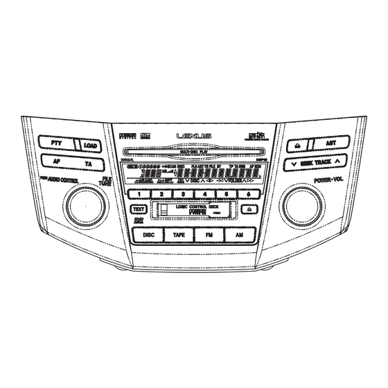
Page 134: Operations
8. OPERATIONS - RADIO - FX-MG8667DVZT/EW PRESET CHANNEL MEMORY PRESET CHANNEL RECALL SEEK TUNING DOWN MANUAL POWER/VOLUME TUNING FM AM - FX-MG8767DVZT/EW PRESET CHANNEL MEMORY PRESET CHANNEL RECALL DOWN SEEK TUNING MANUAL POWER/VOLUME TUNING - DVD / CD DISC - FX-MG8667DVZT/EW... - Page 135 DVD,CD LOAD REPEAT DOWN TEXT TRACK DOWN NUMBER SEARCH / FAST+/FAST- POWER/VOLUME RANDOM DVD,CD PLAY - CASSETTE - FX-MG8667DVZT/EW CHANGE SIDES DOLBY B NR REPEAT AUTO REWIND PROGRAM FORWARD SEARCH POWER/VOLUME TAPE TAPE EJECT - FX-MG8767DVZT/EW CHANGE SIDES DOLBY B NR...
-
Page 136: Jigs List
PIONEER CORPORATION 4-1, Meguro 1-chome, Meguro-ku, Tokyo 153-8654, Japan PIONEER ELECTRONICS (USA) INC. P.O. Box 1760, Long Beach, CA 90801-1760, U.S.A. PIONEER EUROPE NV Haven 1087, Keetberglaan 1, 9120 Melsele, Belgium PIONEER ELECTRONICS ASIACENTRE PTE. LTD. 253 Alexandra Road, #04-01, Singapore 159936 PIONEER CORPORATION 2005 K-ZZU.DEC.
Need help?
Do you have a question about the FX-MG8667DVZT/EW and is the answer not in the manual?
Questions and answers