Table of Contents
Advertisement
Quick Links
Advertisement
Table of Contents

Related Manuals for Pioneer FX-M8717ZT


Summary of Contents for Pioneer FX-M8717ZT
- Page 1 Service Manual ORDER NO. CRT2690 ES300 AUDIO SYSTEM RADIO ASSY VEHICLE DESTINATION PRODUCED AFTER TOYOTA PART No. ID No. PIONEER MODEL No. LEXUS ES300 U.S.A., CANADA July 2001 86120-33500 P6817 FX-M8717ZT/UC Manufactured for TOYOTA CRT2690 by PIONEER CORPORATION PUB. NO.
-
Page 2: Table Of Contents
FX-M8717ZT FX-M8717ZT/UC P6817 - This service manual should be used together with the following manual(s): Model No. Order No. Mech. Module Remarks CX-916 CRT2300 CD Mech. Module: Circuit Description, Mech.Description, Disassembly CX-631 CRT1640 Cassette Mech. Module: Mech.Description, Disassembly - Dolby noise reduction manufactured under license from Dolby Laboratories Licensing Corporation. -
Page 3: Safety Information
FX-M8717ZT - CD Player Service Precautions 3. Please checking the grating after changing the ser- 1. For pickup unit(CXX1286) handling, please refer vice pickup unit(see page 60). to"Disassembly"(see page 73). During replacement, handling precautions shall be taken to prevent an electrostatic discharge(protection by a short pin). -
Page 4: Exploded Views And Parts List
FX-M8717ZT 2. EXPLODED VIEWS AND PARTS LIST 2.1 EXTERIOR(1/2) - Page 5 FX-M8717ZT NOTE: - Parts marked by “*” are generally unavailable because they are not in our Master Spare Parts List. - Screws adjacent to ∇ mark on the product are used for disassembly. - EXTERIOR(1/2) SECTION PARTS LIST Mark No. Description Part No.
- Page 6 FX-M8717ZT 2.2 EXTERIOR(2/2)
- Page 7 FX-M8717ZT - EXTERIOR(2/2) SECTION PARTS LIST Mark No. Description Part No. Mark No. Description Part No. EXK3891 21 Holder CNC9092 Cassette Mechanism Module 2 Screw BMZ26P050FMC 22 Screw BMZ30P060FMC CXK5225 23 Transistor(Q820,830,850) 2SB1185 CD Mechanism Module(S8T) 4 Connector CDE6419 24 Terminal(CN803)
- Page 8 FX-M8717ZT 2.3 CD MECHANISM MODULE...
- Page 9 FX-M8717ZT - CD MECHANISM MODULE SECTION PARTS LIST Mark No. Description Part No. Mark No. Description Part No. 1 Control Unit(S8TECU) CWX2609 46 Sheet CNM6215 2 Connector(CN802) CKS2192 47 Ball CNR1189 3 Connector(CN801) CKS2193 48 Belt CNT1086 4 Connector(CN701) CKS2773...
- Page 10 FX-M8717ZT 2.4 CASSETTE MECHANISM MODULE...
- Page 11 FX-M8717ZT - CASSETTE MECHANISM MODULE SECTION PARTS LIST Mark No. Description Part No. Mark No. Description Part No. 1 Screw BSZ20P040FMC 31 Gear ENV1347 2 Washer CBF1037 32 Collar ENV1508 3 Washer CBF1038 33 Gear ENV1350 4 Washer CBG1003 34 Flywheel...
-
Page 12: Block Diagram And Schematic Diagram
FX-M8717ZT 3. BLOCK DIAGRAM AND SCHEMATIC DIAGRAM 3.1 BLOCK DIAGRAM MAIN UNIT FM/AM TUNER UNIT AM NOISE CANCELER IC 581 FM/AM 1ST IF 10.7MHz FM FRONT END HA12181FP AMDET T31 Q31 CF51 CF52 CF53 CN532 SUB ANTENNA 9 10 CN531... - Page 13 FX-M8717ZT AVC-LAN INPUT IC451 LANL ISOLATOR ISOLATOR E-VOL NJM2068MD IC401-1 IC401-2 FRONTL ZCIN MIXING AMP NJM2068MD NJM2068MD IC351 TUNL VRIN REARL IC403-1 IC403-2 NJM2068MD NJM2068MD NJM2068MD TAPEL IC301 PMJ002A ILL+ AMPB MUTE Q880 SYS8 AMP MUTE Q931 CN801 AMPMUTE Q881...
- Page 14 FX-M8717ZT 3.2 OVERALL CONNECTION DIAGRAM(GUIDE PAGE) Note: When ordering service parts, be sure to refer to “EXPLODED VIEWS AND PARTS LIST” or “ELECTRICAL PARTS LIST”. VDD 5V REGULATOR AMP+B DRIVE Large size SCH diagram 4.97V 6.02V 6.04V > CD 9V REGULATOR 8.74V...
- Page 15 FX-M8717ZT AM:-16.0dBs AVC-LAN(1kHz 0dB):+8.21dBs FM:-16.0dBs 13.2V MAIN UNIT CD-S: +4.5dBs TAPE: -1.8dBs AVC-LAN: +4.5dBs E-VOL AM:-15.5dBs FM:-15.5dBs CD-S:+5.2dBs TAPE:-2.2dBs AVC-LAN: +6.2dBs TAPE MUTE AM:-16.0dBs FM:-30.0dBs CD-S:+0.2dBs TAPE:-7.2dBs AVC-LAN: +8.2dBs NOTE : Symbol indicates a resistor. AUDIO 4V Decimal points for resistor...
- Page 16 FX-M8717ZT...
- Page 17 FX-M8717ZT...
- Page 18 FX-M8717ZT...
- Page 19 FX-M8717ZT...
- Page 20 FX-M8717ZT 3.3 FM/AM TUNER UNIT FM/AM TUNER UNIT FM FRONT END AM OSC FM OSC AM RF FM,AM FM,AM...
- Page 21 FX-M8717ZT FM,AM FM IF...
-
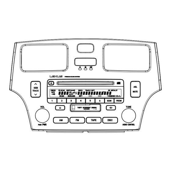
Page 22: Keyboard Unit
FX-M8717ZT 3.4 KEYBOARD UNIT KEYBOARD PCB KEY BOARD UNIT Consists of TAPE EJECT KEYBOARD PCB RIGHT PCB LEFT PCB CD EJECT LCD DRIVER AND KEY CONTROLLER LCD1804 : CAW1636... - Page 23 FX-M8717ZT RIGHT PCB TUNE/ AUDIO CONTROL TAPE SCAN P.SCAN DISC MUTE 5.0V 6.0V 8.1V LEFT PCB PWR/ DOWN...
- Page 24 FX-M8717ZT 3.5 CD MECHANISM MODULE CONTROL UNIT (S8TECU) PU UNIT(SERVICE)(P8) PHOTO UNIT (S8)
- Page 25 FX-M8717ZT SWITCHES: (S8TECU) CONTROL UNIT S801 : HOME SWITCH..ON-OFF S802 : CLAMP SWITCH..ON-OFF The underlined indicates the switch position.
- Page 26 FX-M8717ZT Note:1. The encircled numbers denote measuring pointes in the circuit diagram. 2. Reference voltage REFO:2.5V - Waveforms 1 RFI 1 CH1: RFI 1 CH1: RFI 0.5V/div. 0.5µs/div. 1V/div. 1V/div. 0.5ms/div. 0.5ms/div. 2 CH2: MIRR 2 CH2: MIRR Normal mode: play 5V/div.
- Page 27 FX-M8717ZT 8 CH1: TE 8 CH1: TE 0 MD 0.2V/div. 0.5V/div. 0.5V/div. 0.1s/div. 20ms/div. 5ms/div. 9 CH2: TD ! CH2: SD 0.2V/div. 0.5V/div. Normal mode: play TEST mode: 100 Tracks jump(FWD) Normal mode: Play (12cm) → REFO → REFO →...
- Page 28 FX-M8717ZT ( CH1: R OUT 6 CH1: FE 8 CH1: TE 1V/div. 0.2V/div. 0.2V/div. 0.2ms/div. 1ms/div. 1ms/div. ) CH2: L OUT 9 CH2: TD 3 CH2: FD 1V/div. 0.5V/div. 0.5V/div. Normal mode: Play (1kHz 0dB) Normal mode: During AGC Normal mode: During AGC →...
- Page 29 FX-M8717ZT...
-
Page 30: Cassette Mechanism Module
FX-M8717ZT 3.6 CASSETTE MECHANISM MODULE DECK UNIT CN252 VR302 CCP1280 Q271 33K(B) 2SC4116 R260 R258 C253 390P Rev-L R284 0R0 R275 R256 C254 390P Rev-R MSGV(R) NFI(L) R283 0R0 R403 C405 R03 RIN(L) MAOUT C271 R287 C404 R01 IC251 Fwd-R... - Page 31 FX-M8717ZT PCB UNIT M1 MOTOR UNIT (MAIN MOTOR) CN253 EXA1499 LOAD R375 load 70µs ESG1004 R373 ESG1004 4116 R277 220K R362 R275 MODE SENSE C405 R033 R404 270K EGN1 EGN1005 CN254 MOTOR UNIT (SUB MOTOR) EGN2 EGN3 VCC2 EXA1382 EGN1006...
-
Page 32: Pcb Connection Diagram
FX-M8717ZT 4. PCB CONNECTION DIAGRAM 4.1 MAIN UNIT MAIN UNIT NOTE FOR PCB DIAGRAMS 1. The parts mounted on this PCB include all necessary parts for several destination. For further information for respective destinations, be sure to check with the schematic dia- gram. - Page 33 FX-M8717ZT SIDE A CAR HARNESS CAR HARNESS MAIN ANTENNA ANTENNA FRONT...
- Page 34 FX-M8717ZT MAIN UNIT...
- Page 35 FX-M8717ZT SIDE B...
- Page 36 FX-M8717ZT 4.2 FM/AM TUNER UNIT SIDE A FM/AM TUNER UNIT...
- Page 37 FX-M8717ZT SIDE B FM/AM TUNER UNIT...
- Page 38 FX-M8717ZT 4.3 KEYBOARD PCB 2 4 6 8 10 CN1901 1 3 5 7 9 SIDE A KEYBOARD PCB 2 4 6 8 10 CN1902 1 3 5 7 9...
- Page 39 FX-M8717ZT SIDE B CN701 KEYBOARD PCB...
- Page 40 FX-M8717ZT 4.4 CD MECHANISM MODULE CONTROL UNIT(S8TECU) SIDE A HOME PHOTO UNIT(S8)
- Page 41 FX-M8717ZT CONTROL UNIT(S8TECU) SIDE B CLAMP...
- Page 42 FX-M8717ZT 4.5 CASSETTE MECHANISM MODULE DECK UNIT CN703 SIDE A CN251 C271 C321 DECK UNIT SIDE B IC,Q Q352 R292 R358 VR301 Q271 Q352 C353 VR301 Q271 Q351 R373 Q351 R278 R284 C356 CN252 R375 R374 R276 R356 R281 R277...
- Page 43 FX-M8717ZT PCB UNIT SIDE A LOAD SW 70µs SW MODE SENSE EGN1 PCB UNIT SIDE B 6 5 4 3 2 1 CN253 MOTOR UNIT (MAIN MOTOR) REEL PCB...
- Page 44 FX-M8717ZT 4.6 RIGHT PCB RIGHT PCB RIGHT PCB SIDE A SIDE B MUTE CN1802 TUNE AUDIO CONTROL...
- Page 45 FX-M8717ZT 4.7 LEFT PCB LEFT PCB LEFT PCB SIDE B SIDE A DOWN CN1803...
-
Page 46: Electrical Parts List
FX-M8717ZT 5. ELECTRICAL PARTS LIST NOTE: - Parts whose parts numbers are omitted are subject to being not supplied. - The part numbers shown below indicate chip components. Chip Resistor RS1/_S___J,RS1/__S___J Chip Capacitor (except for CQS..) CKS.., CCS.., CSZS..=====Circuit Symbol and No.===Part Name Part No. - Page 47 FX-M8717ZT =====Circuit Symbol and No.===Part Name Part No. =====Circuit Symbol and No.===Part Name Part No. ------ ------------------------------------------ ------------------------- ------ ------------------------------------------ ------------------------- RS1/16S223J CEAL3R3M50 RS1/16S393J CKSYB474K16 RS1/16S104J CEAL220M6R3 RS1/16S0R0J CKSQYB104K16 RS1/16S242J CKSQYB104K16 RS1/16S473J CEAL3R3M50 RS1/16S103J CKSRYB102K50 RS1/16S104J CCSRCH100D50 RS1/16S104J CKSRYB103K25 RS1/16S103J...
- Page 48 FX-M8717ZT =====Circuit Symbol and No.===Part Name Part No. =====Circuit Symbol and No.===Part Name Part No. ------ ------------------------------------------ ------------------------- ------ ------------------------------------------ ------------------------- RS1/16S393J Unit Number : CWM7355 RS1/16S182J Unit Name : Main Unit RS1/16S304J RS1/16S0R0J MISCELLANEOUS RS1/16S103J NJM2068MD RS1/16S103J NJM2068MD RS1/16S123J...
- Page 49 FX-M8717ZT =====Circuit Symbol and No.===Part Name Part No. =====Circuit Symbol and No.===Part Name Part No. ------ ------------------------------------------ ------------------------- ------ ------------------------------------------ ------------------------- Diode 1SS355 RESISTORS Diode 1SS355 Diode 1SS355 RS1/16S101J Diode 1SS355 RS1/16S101J Diode 1SS355 RS1/16S101J RS1/16S101J Chip Diode MA151WK RS1/16S101J...
- Page 50 FX-M8717ZT =====Circuit Symbol and No.===Part Name Part No. =====Circuit Symbol and No.===Part Name Part No. ------ ------------------------------------------ ------------------------- ------ ------------------------------------------ ------------------------- RS1/16S103J RS1/16S473J RS1/16S103J RS1/16S473J RS1/16S473J RS1/16S473J RS1/16S473J RS1/16S102J RS1/16S103J RS1/16S331J RS1/16S103J RS1/16S0R0J RS1/16S272J RS1/16S0R0J RS1/16S272J RS1/16S102J RS1/16S822J RS1/16S222J RS1/16S822J...
- Page 51 FX-M8717ZT =====Circuit Symbol and No.===Part Name Part No. =====Circuit Symbol and No.===Part Name Part No. ------ ------------------------------------------ ------------------------- ------ ------------------------------------------ ------------------------- RS1/16S473J RS1/16S393J RS1/16S104J RS1/16S393J RS1/16S473J RS1/16S102J RS1/16S102J RS1/16S473J RS1/16S102J RS1/16S473J RS1/16S473J RS1/16S473J RS1/16S472J RS1/16S473J RS1/16S101J RS1/16S473J RS1/16S101J RS1/16S473J RS1PMF680J...
- Page 52 FX-M8717ZT =====Circuit Symbol and No.===Part Name Part No. =====Circuit Symbol and No.===Part Name Part No. ------ ------------------------------------------ ------------------------- ------ ------------------------------------------ ------------------------- RS1/16S104J CKSRYB222K50 RS1/16S222J CEAL3R3M50 RS1/16S222J CEAL3R3M50 RS1/16S102J CKSRYB102K50 RS1/16S222J CKSRYB102K50 RS1/16S104J CKSRYB472K50 RS1/16S102J CKSRYB472K50 RS1/16S222J CKSRYB222K50 RS1/16S104J CKSRYB222K50 RS1/16S221J...
- Page 53 FX-M8717ZT =====Circuit Symbol and No.===Part Name Part No. =====Circuit Symbol and No.===Part Name Part No. ------ ------------------------------------------ ------------------------- ------ ------------------------------------------ ------------------------- CCSRCH101J50 CKSRYB102K50 CKSRYB102K50 CCSRCH681J50 CEAL330M10 CKSRYB222K50 CKSRYB102K50 CEAL3R3M50 CEAL330M10 CKSRYB223K25 CEAL101M10 CEALNP1R0M50 CKSRYB102K50 CQMA683J50 CEAL330M10 CQMA333J50 CKSRYB102K50 CQMA333J50 CEAL330M10...
- Page 54 FX-M8717ZT =====Circuit Symbol and No.===Part Name Part No. =====Circuit Symbol and No.===Part Name Part No. ------ ------------------------------------------ ------------------------- ------ ------------------------------------------ ------------------------- CEAL1R0M50 CAPACITORS CKSRYB103K50 CKSQYB103K50 CKSRYB391K50 CKSRYB102K50 CKSRYB391K50 CKSRYB103K50 CKSRYB391K50 CKSRYB391K50 CEAL1R0M50 CKSRYB103K50 CEAL1R0M50 CKSRYB103K50 CKSRYB103K50 CEV1R0M50 Unit Number : EWM1030...
- Page 55 FX-M8717ZT =====Circuit Symbol and No.===Part Name Part No. =====Circuit Symbol and No.===Part Name Part No. ------ ------------------------------------------ ------------------------- ------ ------------------------------------------ ------------------------- 1902 Chip LED SML210FC(KL) 1861 RS1/16S102J 1903 Chip LED SML210FC(KL) 1862 RS1/16S103J 1904 Chip LED SML210FC(KL) 1863 RS1/16S121J 1905...
- Page 56 FX-M8717ZT =====Circuit Symbol and No.===Part Name Part No. ------ ------------------------------------------ ------------------------- 1806 CKSRYB104K16 1807 CKSRYB104K16 1810 CKSRYB102K50 1811 CKSRYB102K50 1812 CKSRYB102K50 1813 CKSRYB102K50 1814 CKSRYB102K50 Unit Number : Unit Name : Photo Unit(S8) Photo-transistor CPT231SXTU Photo-transistor CPT231SXTU Inductor LCYBR15J1608 Inductor...
-
Page 57: Adjustment
FX-M8717ZT 6. ADJUSTMENT 6.1 CONNECTION DIAGRAM FX-M8717ZT/UC GM-8317ZT/UC POWER AMP BULLET GGD1269 CONNECTOR 6.2 HOW TO ENTER THE TEST MODE 1+6+DISC 3times Diag. In Contents Full segment light up Display TOYOTA diag. mode S8 Mechanism test mode CD changer test mode CD(S8) error No. - Page 58 FX-M8717ZT 6.3 CD SECTION 1) Precautions 2) Test Mode • This unit uses a single power supply (+5V) for the This mode is used for adjusting the CD mechanism regulator. The signal reference potential, therefore, is module of the device.
- Page 59 FX-M8717ZT - Flow Chart DISC Contens DISC TRACK UP Display DISC 1.7sec. DISC Power On New Test Mode TRACK UP TRACK DOWN Focus Mode Power Off Focus Close /S-curve/ Tracking Servo CRG- CRG+ F.EQ Measurement Select Close TRACK UP TRACK DOWN T.Close...
-
Page 60: Checking The Grating After Changing The Pickup Unit
FX-M8717ZT 6.3.1 CHECKING THE GRATING AFTER CHANGING THE PICKUP UNIT • Note : The grating angle of the PU unit cannot be adjusted after the PU unit is changed. The PU unit in the CD mechanism module is adjusted on the production line to match the CD mechanism module and is thus the best adjusted PU unit for the CD mechanism module. - Page 61 FX-M8717ZT Ech → Xch 20mV/div, AC Grating waveform Fch → Ych 20mV/div, AC 0° 30° 45° 60° 75° 90°...
-
Page 62: Connection Diagram
FX-M8717ZT 6.4 TUNER, CASSETTE, AUDIO SECTION - Connection Diagram BACK UP +13.2V DC Regulated Power Supply Lch + 4Ω Lch - Oscilloscope (1) mV Meter (1) GM-8517ZT Rch + 4Ω Rch - Dummy Antenna Antenna Plug 50Ω(37.5Ω) Stereo FM SSG Modulator 50Ω(75Ω) - Page 63 FX-M8717ZT FM ADJUSTMENT Modulation M:MONO MOD., 400Hz 30%(22.5kHz Dev.) S1:STEREO MOD., 1kHz, L or R=30%(20.25kHz+7.5kHz Dev.) NOTE:Before proceeding to further adjustments after switching power ON, let the tuner run for ten minutes to allow the circuits to stabilize. FM SSG...
- Page 64 FX-M8717ZT AM NOISE CANCELER ADJUSTMENT Connection: Output 2-signal pad AM dummy Noise meter FX-M8717ZT/UC Pulse generator (equivalent to HP8011A) Setting of the pulse generator (setting of superimposed pulse) 4Vp-p(EMF) 50µS Adjustment: 1. Setting of SSG Receiving frequency : 1000 kHz...
-
Page 65: General Information
FX-M8717ZT 7. GENERAL INFORMATION 7.1 DIAGNOSIS 7.1.1 TEST MODE - Error Messages If a CD is not operative or stopped during operation due to an error, the error mode is turned on and cause(s) of the error is indicated with a corresponding number. This arrangement is intended at reducing nonsense calls from the users and also for facilitating trouble analysis and repair work in servicing. - Page 66 FX-M8717ZT - New Test Mode S-CD plays the same way as before. If an error such as off focus, spindle unlocking, unreadable sub-code, or sound skipping occurs after setup, its cause and time occurred (in absolute time) are displayed. During setup, operational status of the control software (internal RAM: CPOINT) is displayed.
- Page 67 FX-M8717ZT (4) Display of Operational Status (CPOINT) during Setup Status No. Contents Protective action CD+5V ON process in progress. None Servo LSI initialization (1/3) in progress. None Servo LSI CRAM initialization in progress. None Servo LSI initialization (2/3) in progress.
- Page 68 FX-M8717ZT (5) Display Examples 1) During Setup (When status no. = 11) TRK No. MIN. SEC. 11" 2) During Operation (TOC read, TRK search, Play, FF and REV) The same as in the normal mode. 3) When a Protection Error Occurred Switch to the following displays (A) and (B) using the [4] switch: (A) Error occurrence timing display in absolute time.
-
Page 69: Self-Diagnostic Function
FX-M8717ZT 7.1.2 SELF-DIAGNOSTIC FUNCTION... - Page 70 FX-M8717ZT...
- Page 71 FX-M8717ZT...
- Page 72 FX-M8717ZT...
-
Page 73: Disassembly
FX-M8717ZT 7.1.3 DISASSEMBLY Note) Never hold this figure's upper part such as transfer grille, hazard switch. Hold within the hatchingline part, lower of the illustration. Note) For the installation position is fixed as the factory setting position, never disassemble the bracket which is showed at Fig. - Page 74 FX-M8717ZT Holder Unit Keyboard Unit Removing the Keyboard Unit (Fig.2) Remove the two screws and then remove the Holder Unit. Remove the eleven screws and then remove the Keyboard Unit. Fig.2 Frame Unit Removing the Frame Unit (Fig.3) Remove the five screws and then remove the Frame Unit.
- Page 75 FX-M8717ZT Removing the Case (Fig.4 and Fig.5) Remove the five screws. Remove the screw and then remove the Case. Note) As the installation positions of the left and right brack- ets are fixed, never remove them. Bracket Fig.4 Case Bracket...
- Page 76 FX-M8717ZT Removing the CD Mechanism Module (Fig.6) Chassis Remove the four screws. Disconnect the connector and then remove the CD Mechanism Module. Removing the Chassis (Fig.6) Remove the eight screws. Remove the screw and then remove the Chassis. Note) Never remove the brackets shown in the Fig. 4 and 5 CD Mechanism Module just like the case disassembly.
- Page 77 FX-M8717ZT - Removing the Upper Frame Upper Frame 1. Remove six Springs A, two Springs B and four Screws. 2. Remove two Tabs situated on rear side of the Upper Frame, remove two Arms on the front side, then remove two Tabs on the front side.
- Page 78 FX-M8717ZT - Removing the Guide Arm Assy 1. Remove a connector, a spring A and B Guide Arm Assy Section 2. Drive the Guide Arm Assy up aslant into rear side direction, then remove it from a Pin. Finally, drive the assembly approximately 45 degrees upward, then slide the assembly toward left side to remove it.
- Page 79 FX-M8717ZT - Removing the Loading Motor and Carriage Motor 1. Remove the Spring and two Screws A. Guide 2. Dismount the Loading Motor. 3. Remove the Belt, a Screw B, two Screws C, a Guide Screw Unit Carriage Motor and a Screw Unit.
-
Page 80: Pcb Locations
FX-M8717ZT 7.1.4 PCB LOCATIONS CONTROL UNIT PHOTO UNIT(S8) FM/AM TUNER UNIT MAIN UNIT LEFT PCB PCB UNIT REEL PCB KEYBOARD PCB RIGHT PCB DECK UNIT... -
Page 81: Connector Function Description
FX-M8717ZT 7.1.5 CONNECTOR FUNCTION DESCRIPTION MAIN ANTENNA SUB ANTENNA ILL- SGND BEEP TX- TX+ ILL+ MUTE MUTE SGND MUTE... -
Page 82: Parts
FX-M8717ZT 7.2 PARTS 7.2.1 IC -Pin Function (PD5611A) Pin No. Pin Name Function and Operation LCD driver data output LCD driver clock output Not used KLIGHT Key light control Data output for PLL IC Data input from PLL IC Serial clock output for PLL IC... - Page 83 FX-M8717ZT Pin No. Pin Name Function and Operation VDSENS VD power supply short sensor input SHIMUKE Model select input mode AUDIO mode key input ENC2P AUD encoder(+)input ENC2M AUD encoder(-)input POWER key input ENC1P VOL encoder(+)input Power supply terminal ENC1M...
- Page 84 FX-M8717ZT *PD5611A IC's marked by * are MOS type. Be careful in handling them because they are very liable to be damaged by electrostatic induction. *LC75804W - Pin Functions (LC75804W) Pin No. Pin Name Function and Operation 1–73 SEG01–73 LCD segment signal output 74–77...
-
Page 85: Display
FX-M8717ZT 7.2.2 DISPLAY - CAW1636... -
Page 86: Explanation
FX-M8717ZT 7.3 EXPLANATION 7.3.1 SYSTEM BLOCK DIAGRAM POWER SUPPLY(+B, ACC) AVC-LAN SIGNAL(SOUND) FX-M8717ZT/UC CHANGER EVOL + ASL CDX-M8067ZT/E SIGNAL (UNBALANCE) WOOFER +B, ACC GM-8317ZT/UC... -
Page 87: Operational Flow Chart
FX-M8717ZT 7.3.2 OPERATIONAL FLOW CHART Power ON VDD=5V 16pin,62pin bsens 19pin asens 20pin IPPW 22pin Satrts communication with AVC-LAN SWVDD 35pin Source Keys operative Source ON syspow L 46pin Completes power-on operation. (After that, proceed to each source operation.) -
Page 88: Operations And Specifications
FX-M8717ZT 8. OPERATIONS AND SPECIFICATIONS 8.1 OPERATIONS - CD CD EJECT TRACK SEARCH DOWN POWER ON/OFF VOLUME REPEAT SCAN RANDOM PLAY - RADIO PRESET CHANNEL MEMORY, PRESET CHANNEL RECALL SCAN PRESET SCAN SEEK TUNING DOWN POWER ON/OFF MANUAL VOLUME TUNING... - Page 89 FX-M8717ZT - CASSETTE DOLBY NR AUTO PROGRAM SEARCH DOWN DIRECTION CHANGE TAPE EJECT POWER ON/OFF VOLUME REPEAT BLANK SKIP TAPE - AUDIO MUTE AUDIO MODE SELECT BASS...
-
Page 90: Specifications
PIONEER ELECTRONICS SERVICE INC. P.O.Box 1760, Long Beach, CA 90801-1760 U.S.A. PIONEER EUROPE NV Haven 1087 Keetberglaan 1, 9120 Melsele, Belgium PIONEER ELECTRONICS ASIACENTRE PTE.LTD. 253 Alexandra Road, #04-01, Singapore 159936 C PIONEER CORPORATION 2001 K-ZZS. JUNE 2001 Printed in Japan... - Page 91 Service Manual ORDER NO. CRT2739 ES300 AUDIO SYSTEM RADIO ASSY VEHICLE DESTINATION PRODUCED AFTER TOYOTA PART No. ID No. PIONEER MODEL No. LEXUS ES300 U.S.A., CANADA July 2001 86230-33020 FX-M8717ZT-91/UC Manufactured for TOYOTA CRT2739 by PIONEER CORPORATION PUB. NO.
-
Page 92: Exploded Views And Parts List
CRT1640 Cassette Mech. Module: Mech.Description, Disassembly EXPLODED VIEWS AND PARTS LIST EXTERIOR(1/2)(Page 4) - EXTERIOR SECTION PARTS LIST *: Non Spare Part Part No. Mark No. Symbol and Description FX-M8717ZT/UC FX-M8717ZT-91/UC 1 Screw BPZ30P100FMC Not used 30 Seal CNM7390 Not used... - Page 93 FX-M8717ZT-91 PACKING NOTE: - Parts marked by “*” are generally unavailable because they are not in our Master Spare Parts List. - Screws adjacent to ∇ mark on the product are used for disassembly. - PACKING SECTION PARTS LIST Mark No. Description Part No.
- Page 94 PIONEER ELECTRONICS SERVICE INC. P.O.Box 1760, Long Beach, CA 90801-1760 U.S.A. PIONEER EUROPE NV Haven 1087 Keetberglaan 1, 9120 Melsele, Belgium PIONEER ELECTRONICS ASIACENTRE PTE.LTD. 253 Alexandra Road, #04-01, Singapore 159936 C PIONEER CORPORATION 2001 K-ZZS. JUNE 2001 Printed in Japan...
Need help?
Do you have a question about the FX-M8717ZT and is the answer not in the manual?
Questions and answers