Table of Contents
Advertisement
Quick Links
Advertisement
Table of Contents

Related Manuals for Gentec S-LINK


Summary of Contents for Gentec S-LINK
-
Page 2: Warranty
The warranty does not cover damages related to battery leakage or misuse. Gentec-EO Inc. will repair or replace, optionally, any PC S-Link that proves to be defective during the warranty period, except in the case of product misuse. -
Page 3: Safety Information
Revision 2.8 SAFETY INFORMATION Do not use the PC S-Link with the S-Link if the device or the detector looks damaged, or if you suspect that the S-Link is not operating properly. Appropriate installation must be done for water-cooled and fan-cooled detectors. Refer to the specific instructions for more information. -
Page 4: Table Of Contents
................6 UICK POWER AND ENERGY MEASUREMENT PROCEDURE USER INTERFACE ............................8 1.5.1 Start the PC S-Link software on the PC. Click Start / Programs /GENTEC-EO/ PC S-Link....8 1.5.2 Make a connection with the S-link ......................8 1.5.3 The Real time Display .......................... -
Page 5: List Of Illustrations
Configure TCP/IP protocol on your computer..................35 3.4.2 Setting the IP address in the S-Link ..................... 39 3.4.3 Setting the Ethernet undefault values in the S-Link ................42 TROUBLESHOOTING......................... 45 DECLARATION OF CONFORMITY ......................46 APPENDIX A ............................47 .................. -
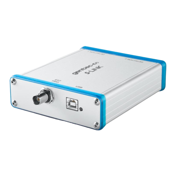
Page 6: The S-Link Double Channel Laser Power/Energy Meter
There is no need to enter the head specifications when connecting the new Gentec-EO power or energy detector heads, for head version 5 and above. The S-Link is already internally set up to accept all the Gentec-EO Hi power wattmeter and joulemeter heads with a DB-15 connector of head version 5 and 6. -
Page 7: Specifications
You can download the latest software version for the PC S-Link (and install it on your PC) and for the S- Link (and install it on the S-Link) with the serial interface anytime from our website www.gentec-eo.com. - Page 8 S-LINK User’s Manual Revision 2.8 Energy meter specifications S-Link Energy Range 8fJ to 20 kJ Energy Scales 33 scales: 1pJ, 3pJ, 10pJ, 30pJ, 100pJ, 300pJ, 1nJ, 3nJ, 10nJ, 30nJ, 100nJ, 300nJ, 1µJ, 10µJ, 30µJ, 100µJ, 300µJ, 1mJ, 3mJ, 10mJ, 30mJ, 100mJ, 300mJ,...
-
Page 9: Connector Descriptions
1.3 Connector Descriptions Fig. 1-2 S-Link-Ethernet Connectors ETHERNET INTERFACE CONNECTOR (optional on S-Link): This interface allows remote control and data transfers between the S-Link and a computer via an Ethernet network, a wireless router or a direct connection. External trigger: The Input connector is a Female BNC. - Page 10 When the S-Link is under power the green led will light-up. The S-link will work under all conditions with 1 HP series high power head and all other supported Gentec-eo heads.
-
Page 11: Getting Started
USB cable into the S-Link and into the PC, and start the software. 1.4 Quick power and energy measurement procedure This section applies to all S-Link versions. It will show you the fastest way of making a laser power and energy measurement with the S-Link and a Gentec-EO power or energy detector. - Page 12 Reconnect. You should see values pertaining to the current settings on the PC S-Link. 15- To replace a head, turn off the PC S-Link, unplug the S-Link, insert the new head, plug in the S- Link, and restart the PC S-Link.
-
Page 13: User Interface
S-LINK User’s Manual Revision 2.8 1.5 USER INTERFACE 1.5.1 Start the PC S-Link software on the PC. Click Start / Programs /GENTEC-EO/ PC S-Link. 1.5.2 Make a connection with the S-link Select communication/open and select the com port, see section 1.7. -
Page 14: The Real Time Display
There is no need for “Zero offset” in energy mode because the S-link compensates for an analog drift. The information bar at the bottom shows the scale and wavelength. The middle box is blank in energy mode. -
Page 15: The Status Window
S-LINK User’s Manual Revision 2.8 1.5.4 The Status Window In the Status window you can select the channel, scale, wavelength, trigger level, correction factor, file name, data sampling and external trig option. All acquisitions and measurements are stopped while you are in the Status Window. To save your settings, select File/ save status. To load your setting, select File/load status. -
Page 16: Adjusting The Windows Display
S-LINK User’s Manual Revision 2.8 1.5.6 Adjusting the Windows Display Select Display/Split with a right click on the window or from the menu bar. To save your layout, select Layout, save layout. To load your saved layout, select Layout, load layout or the filename that appears at... -
Page 17: The Graphic
S-LINK User’s Manual Revision 2.8 1.5.7 The Graphic To adjust the real time graphic double click on the left side of the y axis. The X-Axis minimum and maximum settings are only available in the Load File option. You can use the mouse wheel to zoom in or out. -
Page 18: The Graphic Mode Option After A Load File
S-LINK User’s Manual Revision 2.8 1.5.8 The graphic mode option after a load file In the Status Menu, Select a file name for the file to save or to view. To adjust the graphic axis, double click on the left side of the Y axis. Deselect the Auto mode to enter the axis values. -
Page 19: Restarting The Lineplot, Statistics And Histogram
S-LINK User’s Manual Revision 2.8 1.5.9 Restarting the Lineplot, statistics and Histogram Each window is independent. You can clear each window or use the “Clear All” menu. You can use a Right-click in the Window to select “Clear” or “CLEAR ALL”. When you select Clear the... -
Page 20: Making An Acquisition
A recording message will appear on the bottom of the screen while recording. To stop an acquisition, reselect Acquisition/Channel #. The scale’s quick arrows on the real time display are unavailable during an acquisition. If you do not select a directory, all save files will be in C:\Program Files\Gentec-EO\S- Link. -
Page 21: Ratio Mode
S-LINK User’s Manual Revision 2.8 1.5.13 Ratio mode In energy mode, the ratio is made with the last received measure to the S-link. Ratio mode doesn’t work if you have a power head and an energy head. Example: Laser value channel #1... -
Page 22: Detecting Missing Laser Pulses
The S-link will detect the missing laser pulses using the External Trigger and the Histogram Display. Step1: Connect the External trigger of your Laser to the External trigger of the S-link using the BNC connector. Step2: Select the External trigger from the Status Window. - Page 23 S-LINK User’s Manual Revision 2.8 Step4: Start your laser and place you Cursor on the left x-axis, the upper corner of the histogram will show the number of pulse that are missed. You can reset the histogram using the clear...
-
Page 24: Recommended Pc
S-LINK User’s Manual Revision 2.8 1.5.15 Recommended PC Basic functions work well on PCs dated 2004 and later. If you want to measure higher than 1 kHz and/or display the 3D histogram you have to have a computer and a graphics card like a Intel core 2 CPU 6420 2.13 Ghz, 4 of ram and a Nvidia Geforce 7300 LE or better.. - Page 25 S-LINK User’s Manual Revision 2.8 Go to USB port properties, Select Port parameters and select Advanced.
-
Page 26: Installation And Communication
To Install USB drivers for Windows™: 1.6.1 Plug the S-Link into a USB port on the PC. If the PC supports USB 1.1, Windows detects the new device and prompts you for the software drivers. A window that says Found New Hardware – USB Device opens and after several seconds to a minute the Found New Hardware Wizard appears. -
Page 27: Setting Up Communication To The S-Link
1.7.4.1 Start the PC S-Link Ensure that the S-Link is connected to the PC S-Link by either using the USB cable port or the 9v external power supply for the Ethernet option. See #1.7.1. Verify the COM port to ensure a proper connection. -
Page 28: Exit The Pc S-Link Program
(indicating an error). You must remake the connection if you change the physical connection or the COM port. 1.7.4.3 Exit the PC S-Link program To save some important PC S-Link settings, exit using the File > Exit menu or the Ctrl-F4 hotkey. PC S- Link. 1.7.5 Connect to the S-Link You may use any serial communications software that you are familiar with. -
Page 29: To Echo Commands
The commands you type do not appear in the HyperTerminal window, unless you set the HyperTerminal up to do so. Only the response from the S-Link is displayed. If you prefer to see the commands you are typing, on the HyperTerminal window click the File menu and execute the following sequence: File →... - Page 30 S-LINK User’s Manual Revision 2.8 2:100.231 : 100.231 Watts on channel 2. Energy Mode: 4 digits in scientific notation. 2:8.808e-07 : 0.8808 uJ on channel 2 If you have a repetition rate higher than the ASCII specification, the monitor sends you an error message.
- Page 31 *SS1999: ASCII mode sends 1 out of 999 points ( 999 is the maximum ) *SS2001: ASCII mode sends All points for channel 2 Default value is 0 (Binary mode) Contact Gentec-eo for Binary mode description. Note: The PC-Slink will not work properly if you set the Slink to ASCII mode. *SU1 To make a physical scale up for channel 1 or 2.
- Page 32 S-LINK User’s Manual Revision 2.8 Example : To disable the Energy mode for Channel 1 enter *EM10 . Example : To enable the Energy mode for Channel 2 enter *EM21. You must stop the continuous acquisition (*CS1, *CS2), before sending this command.
- Page 33 S-LINK User’s Manual Revision 2.8 *VNM Activate the *VNP polling mode, This mode is only available in ASCII mode *VNP Deactivate the *CV1 and *CV2 mode (Default mode at power up) *RG1 / Return the current minimum and maximum range for channel 1 or 2.
- Page 34 To set the Scale to Channel 1 or 2. *SC2xx xx = See Table bellow, you send the value for the scale in decimal, but when making a status request the S-link send it in Hexadecimal. You must stop the continuous acquisition (*CS1, *CS2), before sending this command.
- Page 35 S-LINK User’s Manual Revision 2.8 Status definitions *ST1: Status for Channel #1 *ST2: Status for Channel #2 Table 1 Address (first 5 bytes) 4 last bytes Definition in this example Hex Value :000000428 0000 0428 Wavelength in hex value 1064...
-
Page 36: Maintenance
2.1 USB installation for the S-Link The S-Link has a USB type B port. When it is connected to a PC it emulates a standard serial port. It has a simple interface so that it is easy to design software for. The S-Link can function using only the USB port power. -
Page 37: Ethernet Installation Procedure
Revision 2.8 Ethernet Installation Procedure Connect the heads to the S-link, power the S-Link, and connect the S-Link to a Network. Do not connect a USB connector, because the S-Link will switch to USB communication. 3.1 Install these files from the CD. - Page 38 S-LINK User’s Manual Revision 2.8 Select a new Com Port and click ok.
-
Page 39: Route The Ip Address To The New Com Port
Step2: Double Click the IP Address. Select the “Add Rx Port” to set the firewall’s exclusion list if needed. Step3: Click on the blue disk icon to Save the settings. This will add a new Com Port to your computer. You can now run the PC-interface (S-link) to connect to your S-Link. -
Page 40: Setting Up A 2-Node Network With A Windows-Based Computer And S-Link
3.4 Setting up a 2-node network with a Windows-based computer and S-Link For portable applications, or a bench top application where your S-link does not need to be wired into a larger network, you can directly connect your computer to the S-link with a crossover network cable. - Page 41 S-LINK User’s Manual Revision 2.8 Go to Properties...
- Page 42 S-LINK User’s Manual Revision 2.8 Go to TCP-IP Properties...
- Page 43 S-LINK User’s Manual Revision 2.8 Select “Use the Following IP Address” Enter the following Numbers IP: 192.168.0.1 Mask: 255.255.255.0...
-
Page 44: Setting The Ip Address In The S-Link
IP address is available. Ask your network manager to reserve you a fixed IP address if you do not want to reassign the IP to the Com Port each time the S-link asks for an IP in the dynamic IP settings. - Page 45 Set the subnet Mask to: 255.255.255.0 Click OK, then Click on Apply Setting The S-link will reboot itself. Since the IP has changed, the Web configuration will lose its connection. Close the Device installer if the Web configuration doesn’t stop trying to make a connection.
- Page 46 S-LINK User’s Manual Revision 2.8...
-
Page 47: Setting The Ethernet Undefault Values In The S-Link
Revision 2.8 3.4.3 Setting the Ethernet undefault values in the S-Link The PC-S-link uses the high performance Ethernet circuit and communicates at 921600 bps. If you change this value, set it back again. Load the Device Installer from Lantronix. Select The Xport direct+ - firmware IP Select the Web Configuration tab. - Page 48 S-LINK User’s Manual Revision 2.8 Select “Server” option, set the CPU performance to high, and click OK...
- Page 49 S-LINK User’s Manual Revision 2.8 Select “Serial Settings”, set the baudrate to 921600, click OK then “Apply Settings”.
-
Page 50: Troubleshooting
S-LINK User’s Manual Revision 2.8 Troubleshooting. !TRIG Message: The repetition rate of your laser is too high for you PC performance, or you are triggering on noise. Set the trigger to a higher level or upgrade your PC. The Application is not responding when I select Status or when I want to change the Graphic settings: Press the ALT key, your status window may be behind the PCS-Link application. -
Page 51: Declaration Of Conformity
S-LINK User’s Manual Revision 2.8 DECLARATION OF CONFORMITY Application of Council Directive(s): 2004/108/EC EMC Directive Manufacturer’s Name: Gentec Electro Optics, Inc. Manufacturer’s Address: 445 St-Jean Baptiste, suite 160 (Québec), Canada G2E 5N7 European Representative Name: Laser Components S.A.S. Representative’s Address:... -
Page 52: Attenuator/Diffuser Calibration Procedure
When using an oscilloscope or When using a Gentec-EO S-Link or Duo monitor, above. Ensure that the energy level is below the detector’s damage threshhold and your laser is still stable. - Page 53 Add this to your ± uncertainty when you use the attenuator or try to stabilize the laser and the environment. Go back to Step 3. The correction multiplier for the S-Link and an Oscilloscope is calculated: Reading...
-
Page 54: Recycling And Separation Procedure
6.1 Recycling and separation procedure. This section is used by the recycling center when the monitor is at the end of its life. Breaking the calibration seal or opening the monitor will void the S-Link warranty. The complete Monitor contains 1 Monitor... -
Page 55: Fix Com Port Procedure
Connect only 1 device at a time. Start the FT_PROG.exe program. To run the FT_PROG application. 1. Install the USB drivers from the Gentec-eo web site. http://www.gentec-eo.com/en/downloads.htm 2. Download the latest version of FT_PROG from the Utilites section of the FTDI website. - Page 56 S-LINK User’s Manual Revision 2.8 Step#2 Unselect the Serial USB UART in the USB_String_Descriptor Step#3 Select Program in Devices...
- Page 57 S-LINK User’s Manual Revision 2.8 Step #4 Select the Device in the Device list, Click on Program and close the FT_PROG software. Unplug and replug the USB device.
-
Page 58: S-Link-2 Binary Mode Description
8.1 S-LINK-2 BINARY MODE DESCRIPTION 8.1.1 DESCRIPTION The S-LINK-2 has two Communication Modes: the Binary Mode for FAST data acquire and the ASCII mode for slow and high resolution values. The resolution of the Wattmeter Mode is 11- bit, the resolution of the Joulemeter Mode is 12-bit. -
Page 59: Codification
Measurement in Joules = Current Scale * Codification in Decimal/4096 Example: For 151 mJ on the 300 mJ scale on Channel 1 The S-LINK will send you: 600D HEX VALUE, where: 60 = 01100000 The first bit (0) is for Channel #1... - Page 60 S-LINK User’s Manual Revision 2.8...
Need help?
Do you have a question about the S-LINK and is the answer not in the manual?
Questions and answers