Table of Contents
Advertisement
Quick Links
Advertisement
Table of Contents

Related Manuals for Axesstel AX54 Series


Summary of Contents for Axesstel AX54 Series
-
Page 2: Important Notice
20cm away. Axesstel accepts no responsibility for damages of any kind resulting from delays or errors in data transmitted or received using the Axesstel device or for failure of the Axesstel device to transmit or receive such data. -
Page 3: Safety Precautions
Near medical equipment Near life support equipment or any equipment that may be susceptible to any form of radio interference. In such areas, the device MUST BE POWERED OFF. The Axesstel router can transmit signals that could interfere with this equipment. -
Page 4: Limitation Of Liability
FORESEEABLE OR FOR CLAIMS BY ANY THIRD PARTY. Notwithstanding the foregoing, in no event shall Axesstel aggregate liability arising under or in connection with the Axesstel product, regardless of the number of events, occurrences, or claims giving rise to liability. -
Page 5: Table Of Contents
Table of Contents ..Introduction ....................6 ..Product Overview..................6 ..Using your AX54 ..................9 Package Contents ................9 Knowing your Main Unit ...............9 LEDs .....................9 ..Using your AX54 ..................11 Battery Installation / UIM Card Installation into Main Unit ....11 Battery Installation into Motion Sensor..........12 Connecting the Power Adaptor ............13 Placement of Main Unit / Motion Sensor ..........14 4.4.1... - Page 6 Adding / Removing SMS Numbers............18 Adding / Removing Call Numbers ............20 4.10 Arming / Disarming the AX54 ...............21 4.10.1 Arming the AX54................22 4.10.2 Disarming the AX54..............24 4.11 Entry / Exit Delay ..................25 4.11.1 Entry Delay ..................25 4.11.2 Exit Delay..................26 4.12 Panic Button ..................26 4.13 Factory Reset ..................27 ..
-
Page 7: Introduction
Introduction This user manual will help you place, configure and use your AX54 Alert System. Product Overview The AX54 is an easy to install, use and maintain alert system, which can provide peace of mind and security without the need for an expensive security contract. Some features described in this manual may not be supported by your service provider or may not be available with your network account. - Page 8 SMS / Call Alerts if the Motion Sensor is Triggered Notify up to 8 friends and neighbors via call or SMS when motion is detected to increase chances of a close-by responder. You can program up to 3 SMS numbers and 5 call numbers.
- Page 9 Easy to use Main Unit 9 LED indicators represent the product status. The unit is also very easy to program and to modify the list of SMS / Call contacts.
-
Page 10: Using Your Ax54
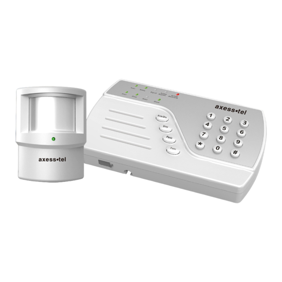
Using your AX54 Package Contents 1x Main Unit • 2x Motion Sensors with brackets • 1x Power Adaptor • Knowing your Main Unit Your AX54 is designed to be wall mounted, or it can simply be placed on a shelf. All the LEDs are easily visible while the power cord will connect at the back. - Page 11 Green Flashing Green Device is Turned Power Device is Off Battery power is Battery No Battery is Battery Full / Medium Power is Low installed Registered to the Signal network and signal Signal is poor No network signal level is good Setting In process of Not in Setting /...
-
Page 12: Using Your Ax54
Using your AX54 Battery Installation / UIM Card Installation into Main Unit Your AX54 main unit may need a UIM Card so that it can communicate with the wireless network. It also supports battery backup. Please follow the instructions below to install the UIM Card and the 9V battery. -
Page 13: Battery Installation Into Motion Sensor
Battery Installation into Motion Sensor To install the battery into the Motion Sensor please follow the instructions below. -
Page 14: Connecting The Power Adaptor
Connecting the Power Adaptor To connect the power adaptor, please follow the instructions below. -
Page 15: Placement Of Main Unit / Motion Sensor
Placement of Main Unit / Motion Sensor 4.4.1 Main Unit The keypad should be placed near the entry / exit point of the house. 4.4.2 Motion Sensor Place on shelves or walls to detect motion within 50 meters, great for rooms with lots of windows. - Page 16 Activate/ Deactivate the PIN Code To toggle between activating and deactivating the PIN Code, please enter the following on your keypad *#→password→07->PIN Code→Func Key Changing your PIN Code You may want to change your UIM Card PIN code to something more memorable to do this you can enter the command below *#→password→08->Existing PIN Code*→New PIN Code→...
-
Page 17: Changing The Default Password
Changing the Default Password Now that the battery is installed and the power adaptor connected you are ready to use some of the more advanced features of the AX54. To change the default password please follow the instructions below. Using your keypad please enter the following *#→password→00->new password*→new password→Func Key NOTE: IT IS ADVISABLE TO CHANGE YOUR PASSWORD AS SOON AS YOU CONNECT THE UNIT... -
Page 18: Adding / Removing Motion Sensors
Adding / Removing Motion Sensors To add motion sensors to the AX54 please follow the instructions below. Up to 64 Motion sensors can be added across 4 zones. *#→password→71→Func Key Trigger the sensor that you want to put in zone1 *#→password→72→Func Key Trigger the sensor that you want to put in zone2 *#→password→73→Func Key Trigger the sensor that you want to put in zone3 *#→password→74→Func Key Trigger the sensor that you want to put in zone4... -
Page 19: Adding / Removing Sms Numbers
*#→password→82→Func Key zone2 *#→password→83→Func Key zone3 *#→password→84→Func Key zone4 Please note that removing sensors will remove all the sensors in the specific zone. Adding / Removing SMS Numbers When your alarm is triggered in any zone, you can choose to send an SMS to up to 3 numbers. - Page 20 Please note that you have to enter the desired number twice. The number that you entered will need to match. If the numbers do not match then the unit will beep 3 times. If the numbers match then you will hear 2 beeps. To remove the SMS numbers please enter the details below.
-
Page 21: Adding / Removing Call Numbers
Adding / Removing Call Numbers When your alarm is triggered as well as sending SMS, the AX54 will also dial 5 numbers of your choice. It is important to note that as the AX54 has no microphone or speaker no conversation will be permissible. To add numbers please follow the instructions below. -
Page 22: Arming / Disarming The Ax54
Please note that you have to enter the desired number twice. The number that you entered will need to match. If the numbers do not match then the unit will beep 3 times. If the numbers match then you will hear 2 beeps. To remove the phone numbers please follow the instructions below. -
Page 23: Arming The Ax54
4.10.1 Arming the AX54 Siren Mode In Siren mode, when the motion sensors are triggered, it will emit a high pitched continuous beep, until the unit is disarmed. To activate Siren mode enter the following: *#→password→01->Arming Key Silent Mode In Silent mode, when the alarm is triggered the high pitched continuous beep will not sound making the intruder unaware that the alarm has been triggered, although SMS / Calls will be sent. - Page 24 Stay Mode Occasionally you may want to alarm only a certain part of your house, and this can be achieved by using Stay mode. Please note that Zone 4 will only be triggered when using stay mode. In Stay mode, you can activate your alarm so that any motion in zones one, two or three will not trigger the alarm, but if there is any movement in zone four then the alarm will be triggered.
-
Page 25: Disarming The Ax54
4.10.2 Disarming the AX54 When disarming the AX54, you can disarm in multiple ways, and these are described below. Normal Disarming To disarm the AX54 in a normal manner enter the following: *#->password->05->Arming Key Normal disarming Duress Disarming If you are forced to disarm the unit under duress, then SMS / Calls will still be made to the numbers that are stored in your device. -
Page 26: Entry / Exit Delay
Remote Disarming You can also disarm the AX54 remotely via SMS. To do this the mobile number that you use to disarm the AX54 will need to be programmed as one of the three SMS numbers. To disarm the AX54 by SMS you will simply need to send a text message saying ‘Disarm Alarm’... -
Page 27: Exit Delay
4.11.2 Exit Delay No Exit Delay *#→password→60→Func Key 30 Seconds - *#→password→61→Func Key 60 Seconds - *#→password→62→Func Key 90 Seconds - *#→password→63→Func Key 120 Seconds - *#→password→64→Func Key 4.12 Panic Button Your AX54 features a panic button, that when pressed will immediately activate the siren, as well as alerting your friends and neighbors via SMS and Calls. -
Page 28: Factory Reset
4.13 Factory Reset If your unit malfunctions or develops any form of software fault then it may be necessary to perform a factory reset. To perform a factory reset please enter the following: *#→password→90→Func Key... -
Page 29: Operating Specifications
Operating Specifications For ASK 433MHz,the Main Unit is only for RX function without TX function, and Motion Sensor (AI100) is only for TX function without RX function Main Unit Item Description Main CPU M0516LBN Module QSC6055 Cellular 800 TX: 824MHz ~ 849MHz Band Frequency RX: 869MHz ~ 894MHz... - Page 30 Channel Spacing 30KHz Carrier spacing Channel Band width : 1.23MHz Maximum output power 300mW (24.7dBm) Sensitivity and Dynamic Range : RSSI -104dBm ~ -25dBm < FER = 0.5% PCS 1900 TX: 1850MHz ~ 1910MHz Band Frequency RX: 1930MHz ~ 1990MHz Channel Spacing : 50KHz Carrier spacing Channel Band width : 1.23MHz...
- Page 31 Sensitivity and Dynamic Range : RSSI -104dBm ~ -25dBm < FER = 0.5% Form Factor Molex connector 80PIN Dimension 36.2*30*3.2mm Antenna ASK433M Spring antenna CDMA CDMA Dual SMS number 3 sets phone number...
- Page 32 CALL number 5 sets phone number Zone number 4 zones Power adapter 5V/2A Battery ASK 433Mhz Band Frequency 433.82Mhz-434.02Mhz Carrier spacing 0.2MHz RSSI < -110dBm Working Temperature -10~+50 Storage Temperature -20~+70 Humidity 5% to 95%...
-
Page 33: Motion Sensor (Ai100)
5.2 Motion Sensor (AI100) BS0001 Detection mode Passive infrared signal Molex connector 80PIN Antenna ASK433M Spring antenna Detection range 6-8m Red & Green Not support Tamper switch Support Battery ASK 433Mhz Band Frequency 433.82Mhz-434.02Mhz... - Page 34 Carrier spacing 0.2MHz RSSI < -110dBm Working Temperature -10~+50 Storage Temperature -20~+70 Humidity 5% to 95%...
- Page 35 AXESSTEL ALERT PRODUCTS CONSUMER WARRANTY AND LIMITATION OF LIABILITY THE AXESSTEL ALERT PRODUCT THAT YOU HAVE PURCHASED, WHEN PROPERLY INSTALLED, CAN BE USED TO DETECT MOTION IN A SPECIFIED AREA AND PROVIDE AN ALERT TO TELEPHONES OR PERSONAL DIGITAL ASSISTANTS THAT YOU SPECIFY. THE PRODUCT IS DESIGNED SOLELY TO PROVIDE AN ALERT. IT DOES NOT PROVIDE SECURITY, OR PREVENT INTRUSION, THEFT OR CRIME.
- Page 36 THAT THE PRODUCT WILL NOT BE DISABLED, COMPRISED OR CIRCUMVENTED (BY DISABLING TELEPHONE SERVICE OR IN SOME OTHER WAY). AXESSTEL DOES NOT WARRANT THAT THE PRODUCT WILL DETECT OR PREVENT ALL INTRUSION, LOSS OF PROPERTY OR PERSONAL INJURY OR BURGLARY, HOLD-UP, FIRE, OR MEDICAL PROBLEM;...
- Page 37 OTHERWISE) WILL NOT EXCEED THE PURCHASE PRICE PAID FOR THE PRODUCT WHICH IS THE SUBJECT OF SUCH CLAIM OR CAUSE OF ACTION. NOT INSURANCE. AXESSTEL IS NOT AN INSURER AND IS NOT RESPONSIBLE FOR ACTS OR OMISSIONS OF OTHERS OR FOR EVENTS BEYOND ITS CONTROL. THE PURCHASE PRICE FOR THE PRODUCT HAS NO...
- Page 38 FCC STATEMENT: THIS DEVICE COMPLIES WITH PART 15 OF THE FCC RULES. ITS OPERATION IS SUBJECT TO THE FOLLOWING TWO CONDITIONS: (1) THIS DEVICE MAY NOT CAUSE HARMFUL INTERFERENCE, AND (2) THIS DEVICE MUST ACCEPT ANY INTERFERENCE RECEIVED, INCLUDING INTERFERENCE THAT MAY CAUSE UNDESIRED OPERATION.
- Page 39 —REORIENT OR RELOCATE THE RECEIVING ANTENNA. —INCREASE THE SEPARATION BETWEEN THE EQUIPMENT AND RECEIVER. —CONNECT THE EQUIPMENT INTO AN OUTLET ON A CIRCUIT DIFFERENT FROM THAT TO WHICH THE RECEIVER IS CONNECTED. —CONSULT THE DEALER OR AN EXPERIENCED RADIO/TV TECHNICIAN FOR HELP. CAUTION: CHANGES OR MODIFICATIONS TO THIS UNIT NOT EXPRESSLY APPROVED BY THE PARTY RESPONSIBLE FOR COMPLIANCE COULD VOID THE USER’S AUTHORITY TO OPERATE THE EQUIPMENT.
Need help?
Do you have a question about the AX54 Series and is the answer not in the manual?
Questions and answers